1-6-4
TD709DC
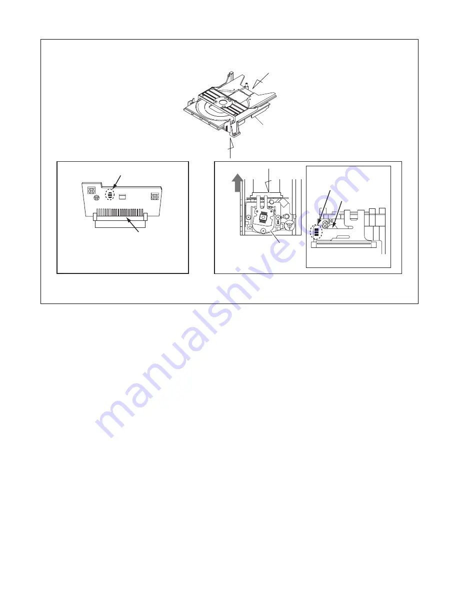
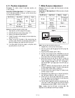
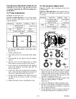
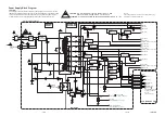
Fig. 4
DVD Mechanism
View for B
Pickup Unit
C
B
Short the three short lands by soldering
FPC Cable
Connector
Slide
View for C
View for A
OR
A
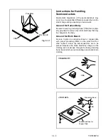
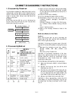
Страница 1: ...SERVICE MANUAL 13 COLOR TV DVD Sec 1 Main Section I Specifications I Adjustment Procedures I Schematic Diagrams I CBA s Sec 2 Exploded views and Parts List Section I Exploded views I Parts List 6513VD...
Страница 2: ...oper ser vice methods may damage the equipment It also is important to understand that these CAUTIONS and NOTICES ARE NOT EXHAUSTIVE Funai could not possibly know evaluate and advice the service trade...
Страница 3: ...ctions 1 5 1 Cabinet Disassembly Instructions 1 6 1 Electrical Adjustment Instructions 1 7 1 FIRMWARE Renewal Mode 1 8 1 Block Diagrams 1 9 1 Schematic Diagrams CBA s and Test Points 1 10 1 Waveforms...
Страница 4: ...worst condition that still might be considered acceptable In no case should a unit fail to meet limit specifica tions Description Condition Unit Nominal Limit 1 Over Scan 90 2 Linearity Horizontal 15...
Страница 5: ...All Items are measured without pre emphasis unless otherwise specified 2 Power supply AC120 V 60 Hz 3 Load imp 100 K ohm 4 Room ambient temperature 25 C ITEM CONDITIONS UNIT NOMINAL LIMIT 1 Coaxial Di...
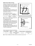
Страница 6: ...ion shown in the figure When checking the laser diode be sure to keep your eyes at least 30cm away from the pickup lens when the diode is turned on Do not look directly at the laser beam Caution Use o...
Страница 7: ...ongs tied together and touch the other ohmme ter lead in turn to each tuner antenna input ex posed terminal screw and if applicable to the coaxial connector If the measured resistance is less than 1 0...
Страница 8: ...ed to the ground side of the AC power source To confirm that the AC power plug is inserted correctly with an AC volt meter measure between the chassis and a known earth ground If a voltage reading in...
Страница 9: ...ot contact sharp edged or pointed parts H When a power cord has been replaced check that 5 6 kg of force in any direction will not loosen it I Also check areas surrounding repaired locations J Be care...
Страница 10: ...er cord plug prongs and externally exposed accessible parts RF terminals antenna terminals video and audio input and output terminals microphone jacks earphone jacks etc Measuring Method Power ON Inse...
Страница 11: ...With Soldering Iron a Using desoldering braid remove the solder from all pins of the Flat Pack IC When you use solder flux which is applied to all pins of the Flat Pack IC you can remove it easily Fi...
Страница 12: ...lder all pins of the Flat Pack IC Make sure that none of the pins have solder bridges Fig S 1 1 Hot air Flat Pack IC Desoldering Machine CBA Flat Pack IC Tweezers Masking Tape Fig S 1 2 Flat Pack IC D...
Страница 13: ...static electricity that may be charged on the body Ground for Work Bench Be sure to place a conductive sheet or copper plate with proper grounding 1M on the work bench or other surface where the semi...
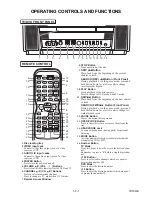
Страница 14: ...ress a 0 before a single digit chan nel 100 Button Press to select cable channels which are equal or greater than number 100 DVD Mode Press to enter the desired number 10 Button Press to enter the des...
Страница 15: ...s you press this button 0 30 60 90 or 120 minutes 18 REV h Button Press to view the DVD picture in fast reverse motion Press PAUSE then press this button to begin slow motion playback Press this butto...
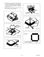
Страница 16: ...Ground Wire before removing the Anode Cap 1 Disconnect the following Anode Cap CN1801 CN1802 CN505 CRT CBA CN1601 and CN1571 Then remove Tray Chassis Unit CAUTION 2 Electrostatic breakdown of the las...
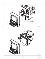
Страница 17: ...1 6 2 TD709DC Fig 1 S 1 S 1 S 2 S 2 S 1 S 1 1 REAR CABINET Fig 2 3 CRT S 3 S 3 S 3 S 3 Anode Cap CRT CBA...
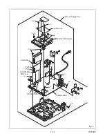
Страница 18: ...1 6 3 TD709DC Fig 3 6 Main CBA 4 DVD Mechanism 5 DVD Main CBA Unit Loder Cover Shield Box 2 Tray Chassis Unit S 4 S 4 S 6 CN301 CN201 S 5 S 5 S 7 S 7 S 7 S 7 S 7 CN002 CN001 S 8...
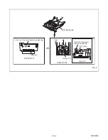
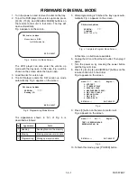
Страница 19: ...1 6 4 TD709DC Fig 4 DVD Mechanism View for B Pickup Unit C B Short the three short lands by soldering Short the three short lands by soldering FPC Cable Connector Slide View for C View for A OR A...
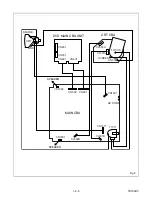
Страница 20: ...TD709DC Fig 5 SCREEN FOCUS CN505 CL501A CL502A CRT CBA DVD MAIN CBA UNIT CN002 CN001 CN1802 CN1601 CN1801 CL502B CL501B CN1571 T1571 AC CORD CN201 CN301 CN601 CN401 MAIN CBA ANODE CRT GND SPEAKER SPE...
Страница 21: ...service remote control unit 2 Turn the power on 3 Press DISC MENU button on the service remote control unit 1 DC 105V B Adjustment Purpose To obtain correct operation Symptom of Misadjustment The pict...
Страница 22: ...l height of screen image Symptom of Misadjustment If V Size is incorrect vertical height of image on the screen may not be properly displayed 1 Operate the unit for at least 20 minutes 2 Enter the Ser...
Страница 23: ...A mode and after zero point calibration bring the optical recep tor to the center on the tube surface CRT 5 Enter the Service mode Press VOL p button on the service remote control unit and select C D...
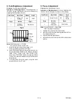
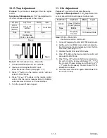
Страница 24: ...isible See above figure 3 Turn the power off and on again using the main power button on the TV unit 9 Focus Adjustment Purpose Set the optimum Focus Symptom of Misadjustment If Focus Adjustment is in...
Страница 25: ...ortion will appear on the screen Note R1583 Main CBA Use Service remote control unit 1 Connect Frequency Counter to R1583 and ground 2 Set the unit to the VIDEO mode which is located be fore CH2 and n...
Страница 26: ...ote control unit and select C D mode Display changes C D 7F DVD KEY and DVD TEST cyclically when VOL p button is pressed then press 1 The display will momentarily show CUT OFF R R Red Now there should...
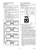
Страница 27: ...t Purpose To obtain proper convergence of red green and blue beams Symptom of Misadjustment If Convergence Adjust ment is incorrect the edge of white letters may have color edges 1 Set the unit to the...
Страница 28: ...et Then plug it again 7 Turn the power on by pressing the power button and the tray will close 8 Press 1 2 3 4 and DISPLAY buttons on the remote control unit in that order Fig d appears on the screen...
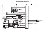
Страница 29: ...TROL BLOCK DVD SECTION CN401 FROM TO AUDIO BLOCK P ON H CN001 Q1622 P DOWN Q1285 DVD L KEY 1 KEY 0 REMOTE RS1201 IC1202 MEMORY SCL 6 SDA 5 MAIN CBA TV MICON VIDEO CHROMA DEFLECTION 55 76 SP MUTE 79 VO...
Страница 30: ...WF18 CN002 DVD Y 1 DVD C 3 TP1733 DVD Y J1734 DVD C TP1301 VIDEO OUT FROM DIGITAL SIGNAL PROCESS BLOCK DVD SECTION CN601 CF1031 CF1032 VCO F B IC1001 IF SIGNAL PROCESS SAW FILTER VIF AMP VIDEO DET VC...
Страница 31: ...SELECT SW CTL 14 15 12 13 2 1 10 11 TUNER TUNER LINE LINE L CH R CH Q1454 SPDIF 10 DVD AUDIO R 8 DVD AUDIO L 7 DVD A MUTE 6 FROM DVD AUDIO BLOCK DVD SECTION CN601 TO SYSTEM CONTROL BLOCK CN002 AUDIO R...
Страница 32: ...CBA CRT CBA R G B HEATER ANODE GND V501 CRT GND FOCUS SCREEN JK501 HEATER 3 3 CN505 CL501A CL501B VIDEO SIGNAL TUNER LINE CN1571 160V 1 1 FROM TO IF VIDEO BLOCK 11 S F HV FOCUS VR SCREEN VR 1 9 8 1 9...
Страница 33: ...ts in the power supply circuit are not defective before you connect the AC plug to the AC power supply Otherwise it may cause some components in the power supply circuit to fail P ON 12V P ON 8V P ON...
Страница 34: ...36 864MHz OSC SPINDLE MOTOR DRIVE TRACKING ACTUATOR DRIVE EXT CLOCK CLK33M BE CLOCK 172 170 150 TRAY OUT TRAY IN FG IN 97 SLD 70 SPDL 71 TRACKING DRIVE 152 FOCUS DRIVE 60 66 TO DIGITAL SIGNAL PROCESS...
Страница 35: ...T ROM DATA ROM INST ROM SERIAL D A GENERAL I O INTERRUPT CONTROLLER TIMER WATCH DOG TIMER 32BIT CPU STREAM I F EXTERNAL MEMORY I F SDRAM ECC UMAC 124 125 122 123 128 129 126 127 131 130 135 133 132 13...
Страница 36: ...ERIAL PORT SERIAL CONTROL 4X 8X OVERSAMPLING DIGITAL FILTER FUNCTION CONTROLLER ENHANCED MULTI LEVEL DELTA SIGMA MODULATOR DAC LPF AMP L CH R CH LPF AMP DAC SYSTEM CLOCK PCM BCK SPDIF PCM DATA0 PCM LR...
Страница 37: ...identified by the mark in the schematic diagram and the parts list Before replacing any of these components read the parts list in this manual carefully The use of substitute replacement parts that d...
Страница 38: ...e parts list section of the service manual 4 Wire Connectors 1 Prefix symbol CN means connector can disconnect and reconnect 2 Prefix symbol CL means wire solder holes of the PCB wire is soldered dire...
Страница 39: ...EO TV LINE SIGNAL VIDEO TV LINE DVD VIDEO SIGNAL DVD VIDEO SIGNAL Main 1 6 Schematic Diagram TV Section 1 10 3 1 10 4 TD709SCM1 MAIN 1 6 Ref No Position IC1201 B 2 Q1285 B 1 Q1301 E 1 Q1303 D 1 Q1304...
Страница 40: ...2 K3 K4 L1 L2 L3 L4 VIDEO TV LINE SIGNAL AUDIO TV LINE SIGNAL 1 10 5 1 10 6 TD709SCM2 Main 2 6 Schematic Diagram TV Section MAIN 2 6 Ref No Position IC1001 J 1 IC1202 J 3 IC1452 H 1 Q1454 I 1 TP1401 I...
Страница 41: ...L AUDIO TV LINE SIGNAL DATA AUDIO SIGNAL 1 10 7 1 10 8 TD709SCM3 Main 3 6 Schematic Diagram TV Section MAIN 3 6 Ref No Position IC1801 O 3 Q1282 N 2 Q1731 Q 3 Q1736 M 1 CN002 R 2 CN1801 M 3 CN1802 M 4...
Страница 42: ...YPE DE 4A 125V 4A 125V CAUTION Fixed voltage or Auto voltage selectable power supply circuit is used in this unit If Main Fuse F1601 is blown check to see that all components in the power supply circu...
Страница 43: ...BB2 BB3 CC1 CC2 CC3 1 10 11 1 10 12 TD709SCM5 Main 5 6 Schematic Diagram TV Section MAIN 5 6 Ref No Position IC1602 Z 2 IC1603 AA 3 IC1604 Z 3 Q1615 BB 3 Q1619 Z 3 Q1621 BB 2 Q1622 BB 2 Q1623 AA 1 CN0...
Страница 44: ...6 CRT Schematic Diagram TV Section MAIN 6 6 Ref No Position IC1551 DD 3 Q1571 FF 2 Q1572 EE 3 Q1591 EE 2 CL501B GG 2 CL502B GG 2 CN1571 EE 3 J2023 FF 2 TP1501 FF 1 TP1502 FF 1 TP1503 FF 1 TRANSISTORS...
Страница 45: ...O AUDIO TRACKING SERVO SIGNAL SPINDLE SERVO SIGNAL SLED SERVO SIGNAL 1 10 15 1 10 16 TD709SCD1 DVD Main 1 3 Schematic Diagram DVD Section DVD MAIN 1 3 Ref No Position IC201 B 1 IC202 E 4 IC301 D 3 IC4...
Страница 46: ...K4 L1 L2 L3 L4 DVD VIDEO SIGNAL DATA VIDEO AUDIO SPINDLE SERVO SIGNAL SLED SERVO SIGNAL FOCUS SERVO SIGNAL TRACKING SERVO SIGNAL DATA AUDIO SIGNAL 1 10 17 1 10 18 TD709SCD2 DVD Main 2 3 Schematic Diag...
Страница 47: ...0 1 127 2 0 2 0 32 64 96 3 4 3 4 128 2 0 2 0 PIN NO PLAY STOP PIN NO PLAY STOP PIN NO PLAY STOP PIN NO PLAY STOP 129 2 0 2 0 161 193 225 1 9 1 9 130 2 2 2 2 162 1 4 1 4 194 0 0 226 3 3 3 3 131 2 3 2...
Страница 48: ...Q3 Q4 R1 R2 R3 R4 DVD AUDIO SIGNAL DVD VIDEO SIGNAL DATA AUDIO SIGNAL 1 10 21 1 10 22 TD709SCD3 DVD Main 3 3 Schematic Diagram DVD Section DVD MAIN 3 3 Ref No Position IC102 O 4 IC103 O 3 IC104 N 3 I...
Страница 49: ...AC plug to the AC power supply Otherwise it may cause some components in the power supply circuit to fail This number 12 Type A This number 13 Type B NOTE Either type A or Type B of MMA CBA Main CBA...
Страница 50: ...voltage for parts in hot circuit is measured using hot GND as a common terminal CAUTION FOR CONTINUED PROTECTION AGAINST RISK OF FIRE REPLACE ONLY WITH SAME TYPE 4A 125V FUSE ATTENTION UTILISER UN FUS...
Страница 51: ...components in the power supply circuit to fail 1 10 27 BTD808F01013 1 10 28 This number 12 Type A This number 13 Type B Main CBA Top View TV Section Type B NOTE Either type A or Type B of MMA CBA Mai...
Страница 52: ...sured using hot GND as a common terminal CAUTION FOR CONTINUED PROTECTION AGAINST RISK OF FIRE REPLACE ONLY WITH SAME TYPE 4A 125V FUSE ATTENTION UTILISER UN FUSIBLE DE RECHANGE DE M ME TYPE DE 4A 125...
Страница 53: ...Type A CRT CBA Bottom View TV Section Type A NOTE Either type A or Type B of MMA CBA Main CBA and CRT CBA is used The difference between type A and type B is shown in the table below Type A Type B BT...
Страница 54: ...Type B CRT CBA Bottom View TV Section Type B NOTE Either type A or Type B of MMA CBA Main CBA and CRT CBA is used The difference between type A and type B is shown in the table below Type A Type B BT...
Страница 55: ...20 sec Q1571 Base WF8 1DIV 20V 20 sec Q531 Collector WF13 1DIV 0 2V 20 sec CN002 Pin 1 WF17 1DIV 20V 20 sec Q511 Collector WF15 1DIV 1V 0 5msec CN002 Pin 7 WF19 1DIV 1V 0 1 sec CN002 Pin 10 WF20 1DIV...
Страница 56: ...R 8 8 AUDIO 5V 9 9 FS TS DETECTOR 11 2 3 5 6 4 7 FG CBA FG SENSOR TRAY OUT SW3001 SW3002 M SLED MOTOR M SPINDLE MOTOR 1 GND 2 E 3 DVD ON 5V 4 VREF 5 B 6 C 7 D 8 A 9 CD DVD 10 F 11 GND LD 12 CD LD 13 P...
Страница 57: ...ray IN TL221 3 3V 0V 0V 3 3V 0V 1 65V 0V 0V 0V 1 65V 1 65V 1 65V Tray OUT TL220 Sled Drive TP303 Disc Drive TP301 Focus Drive TP304 Tracking Drive Tracking Drive TP302 Tray Close Disc Rotation Play Di...
Страница 58: ...Output 3 58MHz 33 N U Not Used 34 N U Not Used 35 N U Not Used 36 N U Not Used 37 V RAMP F B V Ramp Feed Back 38 V RAMP OUT Vertical Output 39 V RAMP CAP V Ramp OSC Capacitor 40 N U Not Used 41 N U N...
Страница 59: ...untermeasure 73 P SAFETY 1 Power Supply Protection 74 P SAFETY 2 Power Supply Protection 75 P SAFETY 3 Power Supply Protection 76 EXT L Switching External Input 77 DVD MAIN POWER Power On Signal to Hi...
Страница 60: ...1 2 3 4 1 Vin 2 Vo 3 GND 4 Vc R A K KIA431 AT E C B 2SC3400 KTA1266 GR BN1F4M T KTC3199 GR 2SC2785 J H F KRC103M KRA103M BA1F4M T 2SA950 Y O KTA1271 Y 2SA1175 F KTA1267 GR 2SA1015 GR TPE2 2SC2482 TPE...
Страница 61: ...TION 13 COLOR TV DVD 6513VD TABLE OF CONTENTS Cabinet Exploded Views 2 1 1 Packing Exploded Views 2 1 3 Mechanical Parts List 2 2 1 Electrical Parts List 2 3 1 Sec 2 Exploded views and Parts List Sect...
Страница 62: ...880 DG601 L1551 CLN551 CRT CBA TB4 L2 TL2 TL2 TL1 TL1 TL1 TL1 TB1 Main CBA TB5 TL1 TB6 TB2 TL1 TB10 DVD Main CBA Unit TL3 TB14 1B1 TL1 TL2 TL2 TB12 TL1 TL3 A1 3 A1 2 A1 1 A1X A1 7 A1 5 A1 6 A5 B6 B2...
Страница 63: ...FRONT PACKING TAPE S1 S3 S6 X3 X4 X2 X7 X1 X5 TAPE PACKING TAPE S2 PACKING TAPE PACKING TAPE PACKING TAPE S4 Packing 2 1 3 TD709PEX...
Страница 64: ...S MANUAL TD709UK 0EMN02258 X3 REMOTE CONTROL 182 ERC001 NE207UD NE207UD X4 DRY BATTERY R6P UM3 or XB0M451GH001 DRY BATTERY R6P AR 2PX or XB0M451HU002 DRY BATTERY R6P AR 2P X ICI or XB0M451HU003 DRY B...
Страница 65: ...000D9001 V501 3 RUBBER MAGNET 20X10X1 2 XM05000BV001 CRT TYPE G L1551 DEFLECTION YOKE LLBY00ZSY002 or LLBY00ZSY002 DEFLECTION YOKE KDY3GCE83X or LLBY00ZMS027 DEFLECTION YOKE CDY M1456S LLBY00ZQS008 V5...
Страница 66: ...CHIP CERAMIC CAP B K 1000pF 50V CHD1JKB0B102 C1206 CHIP CERAMIC CAP B K 220pF 50V CHD1JKB0B221 C1207 FILM CAP P 0 001 F 50V J or CMA1JJS00102 FILM CAP P 0 001 F 50V J CA1J102MS029 C1209 CHIP CERAMIC C...
Страница 67: ...1 6KV CT3C822HJE16 C1584 ELECTROLYTIC CAP 1 F 160V M or CE2CMASDL1R0 ELECTROLYTIC CAP 1 F 160V M CE2CMASTL1R0 Ref No Description Part No C1591 ELECTROLYTIC CAP 2 2 F 50V M or CE1JMASDL2R2 ELECTROLYTIC...
Страница 68: ...470 F 16V M CE1CMASTL471 C1808 ELECTROLYTIC CAP 100 F 16V M or CE1CMASDL101 ELECTROLYTIC CAP 100 F 16V M CE1CMASTL101 C1809 ELECTROLYTIC CAP 470 F 16V M or CE1CMASDL471 ELECTROLYTIC CAP 470 F 16V M CE...
Страница 69: ...RY DIODE ERB44 02 QDPZ0ERB4402 D1626 ZENER DIODE MTZJT 7736A or QDTA00MTZJ36 ZENER DIODE DZ 36BSAT265 NDTA00DZ36BS Ref No Description Part No D1627 SCHOTTKY BARRIER DIODE 21DQ04 or QDQZ0021DQ04 SCHOTT...
Страница 70: ...QZZ02SC5884 Q1572 TRANSISTOR 2SC1627Y TPE2 QQSY02SC1627 Ref No Description Part No Q1591 TRANSISTOR 2SC2785 F or QQSF02SC2785 TRANSISTOR 2SC2785 H or QQSH02SC2785 TRANSISTOR 2SC2785 J or QQSJ02SC2785...
Страница 71: ...1 4W J 5 6k RCX4JATZ0562 Ref No Description Part No R1231 CHIP RES 1608 1 10W J 47k RRXAJB5Z0473 R1232 CHIP RES 1608 1 10W J 2 7k RRXAJB5Z0272 R1233 CHIP RES 1608 1 10W J 100 RRXAJB5Z0101 R1234 CHIP R...
Страница 72: ...XIDE FILM RES 2W J 0 39 or RN02R39ZU001 METAL OXIDE FILM RES 2W J 0 39 RN02R39DP004 Ref No Description Part No R1612 METAL RESISTOR 1W J 0 56 or RN01R56ZU001 METAL OXIDE FILM RES 1W J 0 56 RN01R56DP00...
Страница 73: ...SWITCH SKHHAM or SST0101AL029 TACT SWITCH KSM0612B or SST0101HH003 TACT SWITCH TC 1104 H 5 0 SST0101DNG02 SW1206 TACT SWITCH SKQSAB or SST0101AL038 Ref No Description Part No TACT SWITCH SKHHAM or SS...
Страница 74: ...50V M or CE1JMASDL010 ELECTROLYTIC CAP 1 F 50V M CE1JMASTL1R0 C511 CHIP CERAMIC CAP B K 330pF 50V CHD1JKB0B331 C521 CHIP CERAMIC CAP B K 330pF 50V CHD1JKB0B331 C531 CHIP CERAMIC CAP B K 330pF 50V CHD...
Страница 75: ...Printed in Japan 2003 09 19 HO 6513VD TD709UK...