SWS Warning Lights Inc. – 7695 Blackburn Pkwy., Niagara Falls, ON, Canada
Tel: 1-877-357-0222 | Fax: 1-905-357-9122 | Email: [email protected]
300392_Rev1
2
|
P a g e
Mounting
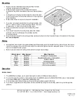
Select a level unobstructed mounting surface for best
visibility and access to the fasteners.
Observed light output will be reduced if the light is
mounted in any other orientation other than vertical (Dome
up).
A straight level is highly recommended to ensure the light
is level on two axes. Ensure the vehicle is on level ground
when installing.
Outer dome does not require removal for installation
1. If you are not using manufacturer mounting brackets, drill
two
5
/
16
” holes 4” apart, in the mounting surface. Be sure
to also drill a ½” hole in the center for the wires.
2. Place a lockwasher onto each bolt, followed by a flat
washer.
3. If you need to seal the mounting hole, place the rubber
washers onto the bolt between the minibar and the
mounting surface.
4. Pass the bolts through the mounting surface and secure them into the threaded holes in the bottom of the base.
Do not overtighten.
Wiring
All extension wires need to be appropriately sized depending upon the length that they are to travel. Be sure to
check the voltage at the end of the wire length to ensure the light will receive adequate power. If not, you may
have to increase the wire gauge.
Refer to product label and selling information for proper input voltage.
Wire Colour
Wire Gauge
Wire Function
Red
20AWG
Positive (+) Connection
Black
20AWG
Negative/Ground (-) Connection
Green
22AWG
Pattern Select
Orange
22AWG
Dimming Option
Blue
22AWG
Sync./Alt. Selection
White
22AWG
LIN Communication
Operation
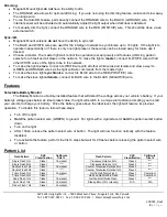
Pattern Select:
1.
The GREEN wire allows you to select amongst a number of different flash patterns.
2.
To scroll through the patterns, momentarily touch the GREEN wire to the RED (POSITIVE) wire or momentarily
touch the GREEN wire to the BLACK (GROUND) wire.
3.
A momentary switch kit will allow you to cycle through patterns (switch 766163)
4.
If you have a cigarette cord, the pattern can be selected by using the momentary switch to cycle through the
patterns.

