


7
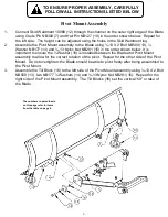
1.
Assemble one 3/8-16 Nut NB212 (4) to each Eyebolt NB635 (5).
2.
Attach one end of Tilt Spring 2335 (6) to the Plow Mount assembly tab and the other end to
Eyebolt NB635 (5).
3.
Assemble Eyebolt NB635 (5) into the hole at the top of the Blade. Secure with 3/8 Washer
NB272 (3) and 3/8-16 Nut NB182 (2). Place Vinyl Caps AS125 (1) over the remaining
threads of the Eyebolt. Repeat for the other side.
Tilt Spring Assembly
TO ENSURE PROPER ASSEMBLY, CAREFULLY
FOLLOW ALL INSTRUCTIONS LISTED BELOW
The numbers in parenthesis
on this page refer to items
from the table on page 4.
Plow Adjustment & Operation
The tension placed on Tilt Springs 2335 (9) determine the amount of pressure that must be applied to the Blade before
it folds over if an obstruction is hit.
Tilt Springs 2335 (9) can be adjusted by turning 3/8-16 Nyloc Nut NB182 (4) on the Eyebolts NB635 (8), making
adjustments until the Blade does not fold over during normal operation but does fold over if an obstruction is hit. Turn
the nut clockwise to tighten the spring and counterclockwise to loosen the spring. Once the desired tension is
achieved, lock the position of Eyebolt NB635 (8) using 3/8-16 Nut NB212 (7).
To change the Blade angle while operating, come to a stop, turn off the ignition and set the parking brake. Disengage
Lever Latch 2840 (26) and rotate the Blade to the desired angle. Engage Lever Latch 2840 (26) making sure it is
secured into one of the latch positions of Pivot Weldment 2323 (23).


