


GB.TBXZ342.130915
Registered design. The company reserves the right to make changes without prior notice.
2 www.swegon.com
2. Installation
2.1 Pipework Package.
1. Install the pipework package at a suitable location in
the fan room.
Wall mounting
Remove the wall mounting bracket from the pipework
package and secure it to a suitable place on a wall. In
order to reach and unfasten the wall mounting bracket,
you must first dismantle the front panel of the sheet-metal
casing.
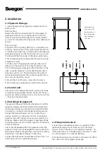
Floor mounting
A stand for floor mounting, TBXZ-2-43, is available as an
accessory, see illustration to the right. Secure the stand to
a suitable spot on the floor. In order to reach the pipework
package and secure it to the stand with screws, you must
first dismantle the front panel of the sheet-metal casing.
2. Mount the pipework package onto the wall mounting
bracket/floor stand.
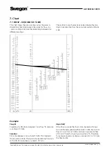
3. Fit the pump to the pipework package. Give careful
attention to the direction of flow. See the label on the
front of the pipework package and the illustration to the
right. It may be necessary to dismantle the drive side of
the pump and turn it so that the electrical terminal box
will be positioned upward. This can be done after remov-
ing four socket head cap screws.
4. Mount the shut-off valve + pipes onto the pump.
5. Mount the pressure expansion vessel and accessories.
2.2 Control unit.
The control unit is designed for wall mounting should be
mounted at an appropriate location. Make sure that you
position the safety isolating switch on the control unit 0.6
– 1.9 metres above floor level.
2.3 Installing the pipework
The pipework between the heat exchanger coils and the
pipework package should be installed and insulated in a
professional manner by a ventilation and sanitation fitter,
according to customary trade standards and regulations.
Connect the heat exchanger coils for counter-flow cir-
culation according to the arrows on the coil connection
branches. Incorrect connection may cause a reduction in
efficiency. Make sure that the pipework package and the
connecting pipework do not block inspection of the other
functional sections.
Check that the deadweight of the pipework and/or the
expansion forces will not be applied to liquid connections.
Use an appropriate sealing/jointing compound for sealing
the threads on the heat exchanger connections.
Connect the safety valve, appropriately using a hose, to a
collecting vessel (not supplied by Swegon ).
M
Supply air
Extract air
The height from
floor level to the
thermometers on
the installed pipe-
work package is
1480 mm.
2.4 Temperature sensor
A type strap-on temperature sensor is supplied with the
pipework package. Secure the sensor onto the return
pipe, as shown in the basic circuit diagram on page 1, for
instance by means of a bundling strap. The sensor is used
as a limiting sensor to counteract freezing.
Wire the temperature sensor leads to terminals 107-108 in
the control unit of the pipework package.


