W9
Smart
28
All rights to changes reserved.
2021-09-23
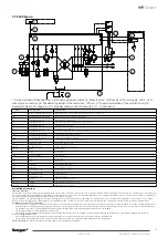
7.7 Control diagram
7.7.1 W9
1
2
3
5
6
7
8
9
10
11
4
1: Group electrical distribution box | 2: Electrical equipment cubicle | 3: Exhaust air | 4: Outdoor air | 5: Power supply: 230 V, 16 A
with plug-in connection | 6: The damming height of the water trap, 100 mm | 7: Supply demarcation of the ventilation unit | 8:
General ventilation | 9: Supply air | 10: Modular cables with RJ9-connectors | 11: Control panel
DESCRIPTION OF FUNCTIONS
CONTROL FUNCTIONS:
The ventilation unit can be operated from a separate Smart control panel or a Smart cooker hood, or remotely via the Modbus field bus or by DCC control. When the ventilation unit is controlled from
the cooker hood in the Home/Away/Boost modes and for local extraction, the time can be set to 30, 60 or 120 minutes. The supply air temperature can be set from the control panel or via Modbus. If
necessary, reheating can be disabled via the settings.
Summer operation: The outside air bypasses the heat exchanger when the room temperature is higher than its set temperature (e.g. T3) and when the temperature of the outside air (T1) is higher
than 14 °C (factory setting) and is lower than the room temperature setting. The fans run at the set speed or are controlled by the control panel to the defined boost speed for summer mode.
INTERLOCKINGS AND SAFETY FUNCTIONS:
–
The air heater for post heat is equipped with an automatic thermostat TZA1 and a thermostat TZ01 with manual reset (set value 90 °C).
–
The air heater for preheat is equipped with an automatic thermostat TZA2 and a thermostat TZ02 with manual reset (set value 90 °C).
–
The fans have automatic overtemperature protective devices.
–
The ventilation unit is equipped with an automatic defrost system that prevents the heat exchanger from freezing by enabling the preheater and if necessary by changing the fan speed.
IF THE SAFETY EQUIPMENT TRIPS:
–
If an overheating protection with manual reset trips, locate and correct the fault; then press the reset button inside the ventilation unit.
–
The automatic overheating protections of the fans will reset themselves when the temperature has dropped below the setting value.
REMOTE OPERATION: Study the ventilation unit manual and the list of parameters for Modbus.
SYMBOL
DESIGNATION
EXPLANATION
TC01
TEMPERATURE CONTROLS
Temperature control for the post heating air heater
T1
TEMPERATURE SENSOR
Temperature sensor, outdoor air
T3
TEMPERATURE SENSOR
Temperature sensor, extract air
T4
TEMPERATURE SENSOR
Temperature sensor, supply air.
T5
TEMPERATURE SENSOR
Temperature sensor, exhaust air
T6–T9
TEMPERATURE SENSOR
Connected to SET, the functions are determined through the programming of SET (accessory)
TZ01, TZ02
OVERHEATING PROTECTION
Overheating protection with manual reset
TZA1, TZA2
OVERHEATING PROTECTION
Automatic over temperature protection
SET
CONNECTION UNIT
Connection unit for Smart control signals (accessory)
SEC
EXPANSION CABLE
IO expansion cable, accessory
SMBG
MODBUS MODULE
Modbus expansion module, accessory
F1 + F2
FILTER
Supply air filter
F3
FILTER
Extract air filter
HR
HEAT EXCHANGER
Heat exchanger
SF1
FAN
Supply air fan
EF1
FAN
Extract air fan
SD1
DAMPERS
Bypass damper summer time
SD2
DAMPERS
Shut-off dampers, accessory
SK
AIR HEATER/COOLER
Electric air heater, accessory
LP
AIR HEATER/COOLER
Air heater accessory
VP
AIR HEATER/COOLER
Air cooler, accessory
RH
SENSOR
Humidity sensor
RH + CO2
SENSOR
Humidity/carbon dioxide sensor, accessory
RH + VOC
SENSOR
Humidity/VOC sensor, accessory


