Swann Safety Camera Kit Wireless Camera & Receiver Скачать руководство пользователя страница 4

The Safety Camera can be switched to any of four frequencies to assist in avoiding 
interference. Please see the illustration 

 for frequency settings. On the power 

cable connected to the camera find the small flap covering the two dip switches. Move 
the switches using the dip switch tool, or a pin according to the images below to set 
the correct channel.  The LEDs on the receiver indicate which channel is currently 
selected.

below

Channel & Frequency 

By changing these switch settings, the frequency that the 
Camera transmits on changes. Once you have set the channel 
on the Camera, select the same channel on the receiver. If you 
experience interference try a different channel. 

Do not set two Cameras to the same channel or they 
will interfere with each other.
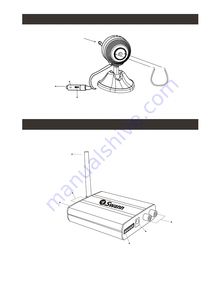
Receiver Features

Camera features

Changing the channel on the camera

Receiver & Remote Control features

2

DC

 1

V

2

DC

 1

V

DC Power Socket

A/V Output

Channel LEDs

Channel selector
Button

External Antenna

DC Power Socket

ON

ON

ON

ON

ON

ON

ON

ON

1   2

1   2

1   2

1   2

1   2

1   2

1   2

1   2

Ch1 - 2414MHz
1 = OFF
2 = OFF

Ch3 - 2450MHz
1 = OFF
2 = ON

Ch2 - 2432MHz
1 = ON
2 = OFF

Ch4 - 2468MHz
1 = ON
2 = ON

DC Power Socket

Channel Switch 

(see “Changing the

 channel on the camera”)

Focus Tool 

(Insert and turn

to focus camera)

Microphone

External Antenna

1

 2


4

 L

3


o

n

1 2 3 4 L
on

Channel Lockout Switch

Channel lockout switch on the receiver

This receiver is equipped with Lockout and Loop features.

The switches are numbered 1,2,3,4 representing 4 camera 
channels. When the switch is in the UP position the camera 
channel is OFF. When the switching between channels the 
receiver will automatically skip channel set to OFF.

Loop mode allows you to see all active camera channels 
set to ON by cycling through channels every few seconds. 
This feature is useful for monitoring cameras or VCR 
recording. Move the L switch to ON to cycle active 
channels.

 
(See next page for details)

 
(See next page for details)

Use the included 
Dip Switch tool to 
change the 
camera channel

Use the included 
Dip Switch tool to 
change the 
camera channel

Содержание Safety Camera Kit Wireless Camera & Receiver

Страница 1: ...mbers shown on the back cover of this booklet Installation Guide FCC INFORMATION This device complies with Part15 of the FCC Rules Operation is subject to the following two conditions 1 This device may cause harmful interference 2 This device must accept any interference received including interference that may cause undesired operation Changes or modifications not expressly approved by the party ...

Страница 2: ...l Accessories Focus Tool Dip Switch Tool If any of these items are missing please contact your retailer Introduction Package Contents NOTE All jurisdictions have specific laws and regulations relating to the use of cameras Before using any camera for any purpose it is the buyer s responsibility to be aware of all applicable laws and regulations that prohibit or limit the use of cameras and to comp...

Страница 3: ... tape or movie on your VCR The AV channel may be activated by a button on your remote that is marked with this symbol or L1 or L2 or possibly AV AV1 or AV2 Check the manual of your TV or VCR for more information on using its AV inputs 3 After connecting both the Camera and the Receiver make sure the receiver is switched to the same channel as the camera Press the Channel Select button on the recei...

Страница 4: ...ket A V Output Channel LEDs Channel selector Button External Antenna DC Power Socket Channel Switch see Changing the channel on the camera Focus Tool Insert and turn to focus camera Microphone External Antenna 1 2 4 L 3 o n Channel Lockout Switch See next page for details See next page for details ...

Страница 5: ...r they will interfere with each other Changing the channel on the camera ON ON ON ON ON ON ON ON 1 2 1 2 1 2 1 2 1 2 1 2 1 2 1 2 Ch1 2414MHz 1 OFF 2 OFF Ch3 2450MHz 1 OFF 2 ON Ch2 2432MHz 1 ON 2 OFF Ch4 2468MHz 1 ON 2 ON DC Power Socket 1 2 3 4 L on Channel lockout switch on the receiver This receiver is equipped with Lockout and Loop features The switches are numbered 1 2 3 4 representing 4 camer...

Страница 6: ...ic exposure can find it difficult to balance the image correctly Change the location of the camera so that the point of greatest interest has the largest area of the image if you want to see the bright area move the camera so that almost all of the screen shows this area If you want to see the darker area move the camera so that most of the image shows this area Change the location of the Camera t...

Страница 7: ...olour CMOS Horizontal Resolution 380 TV lines Auto Electronic Exposure 1 60 1 15000 sec Minimum Illumination 1 Lux f1 2 Signal to Noise Ratio 48dB 7 Board Lens 5 6mm 32 View Angle 60 degrees Video System PAL 50Hz Australia UK Europe NTSC 60Hz USA and Canada Automatic Exposure Gain White balance IR LED activation Available Channels 4 Channels in 2 4Ghz frequency band RF Output Power FCC CE and C ti...

Страница 8: ... Unauthorised end user or third party modifications to any component or evidence of misuse or abuse of the device will render all warranties void product The end user is responsible for all shipping costs incurred when product product Help Desk Support Details Warranty Information www swannsecurity com Swann Technical Support All Countries E mail tech swann com au Telephone Helpdesk See http www w...

Отзывы: