


English
6
Connec
ting the D
VR
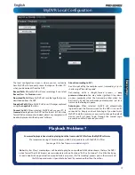
The Rear Panel of the DVR
1) SDI Inputs 1 - 4:
These are the high-definition video inputs
and are where you should connect your 1080p SDI cameras.
These connection use a similar BNC connector to a composite
video channel found on other DVR models, however the
cameras (and some cables) are
not
interchangable.
For the best results , don’t use existing composite video cable
but rather connect your SDI camera(s) with the supplied
cables marked for use with SDI.
2) Audio Inputs:
These will accept a standard line-level signal
(<1V).
3) PTZ (RS485) Port:
To connect the RS485 cables to control a
PTZ (pan, tilt, zoom) device to the DVR.
4) VGA Output:
For connecting a television or PC monitor
with a VGA input.
5) HDMI Output:
The primary output of the DVR. For the
highest possible video output quality, we suggest using this
output.
•
For best results, use a monitor/television capable of
displaying
Full HD 1080p
.
•
Note that many televisions which can display 1080p
signals are not actually
Full HD
. These kinds of televisions
downscale a 1080p signal to the resolution of the screen.
For the best possible image, use a television/monitor
which can display 1920 x 1080 or higher.
6) USB/eSATA1 Port:
To connect an external hard drive or a
flash drive, to which you can
backup footage
. Accepts both
USB and eSATA devices such as:
•
USB flash drives
•
USB hard drives
•
eSATA hard drives.
For the best results use devices which support USB 2.0 (or
higher) speeds.
7) Network Port:
Where you can connect the DVR to a
network, typically directly into the router or network switch.
8) DC 12V Power Input:
Where you connect the included DC
12V power adapter. Use
only
the supplied power adapter with
the DVR, and use the power adapter
only
with the DVR.
9) Audio Output:
A standard line-level audio output.
10) eSATA 2 Port:
For connecting an eSATA hard drive to use
as a primary recording disk. A hard drive connected in this way
will be used to store raw footage in the same way as the DVR’s
internal hard drive(s).
11) Alarm & Sensor I/O Block:
For connecting external
alarm sensors and/or alarm output devices (such as sirens or
lighting) to the DVR.
12) Power Switch:
Master ON/OFF switch.
1
4
3
5
6
7
8
2
11
2
12
10


