background image

1-15-4

W3N4HTI

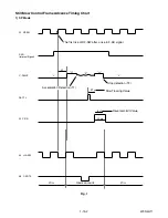
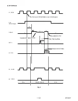
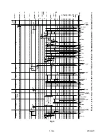
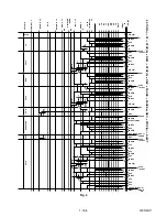
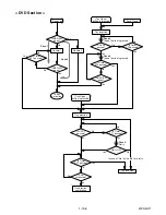
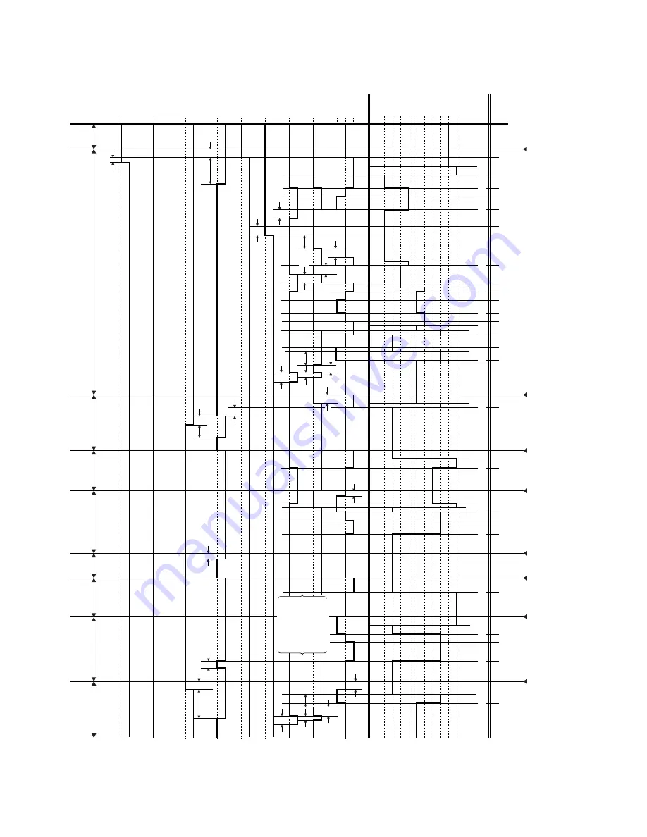
Fig. 3

1.

 EJECT (PO

W
ER OFF) -> CASSETTE IN (PO

WER ON) -> ST

OP(B) -> ST

OP(A) -> PLA

Y

 -> RS -> FS -> PLA

Y

 -> STILL -> PLA

Y

 -> ST

OP(A)

EJECT

CASS.LOAD

ST-S/
END-S
 "OFF"

PLAY

REW

FF

PLAY

PLAY

STOP
/EJECT

0.2S

0.7S

0.4S

0.2S

LD-FWD

STOP(A)

STOP(A)

LD-FWD

LD-REV

0.2S

LD-FWD

LD-FWD

LD-FWD

LD-FWD

LD-FWD

STILL(SLOW)

RS

FS

PLAY

PLAY

PLAY

0.2S

LD-REV

LD-REV

LD-FWD

LD-FWD

LD-REV

LD-REV

LD-REV

0.2S

0.5S

PIN NO

.

CL

EJ

SS

SS

AU

AU

TL

LD-SW

CL/SS

LM-FWD "M"

/REV

C-DRIVE

"Z"

ON

ON

C-F/R

DR

UM

R

O

T

A

TION

P-ON-L

A-MUTE-H

D-REC-H

D-PB

PAUSE
(SLOW)

AU

AL

AL

AU

SF

SM

EJ

AU

RS

SF

SM

TL

FB

AL

SB

87

26

32

27

31

29

TV/VIDEO

9

PO
WER

-OFF

ST
OP

PLA

Y

R

S

FS

STILL

(SLO

W)

PLA

Y

S

T

O

P

PLA

Y

DISPLA

Y

0.1S

SB

TL

SB

FB

SM

SM

SF

AL

AL

RS

A

U

AL

SS

A

U

AL

SM

0.8S

0.2S

0.3S

1.0S

0.2S

1.5S (2H)

2.5S (4H)

0.5S

0.2S

0.8S (2H)

1.2S (4H)

0.2S

1.2S

0.2S

20mS

0.4S

40mS

0.2S

0.2S

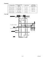
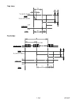
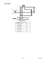
Ref
er to STILL/

SLO

W TIMING 

CHAR

T Fig.

 1, 2.

0.3S

0.2S

20mS

40mS

0.4S

0.2S

0.2S

0.2S

0.3S

Содержание CWV20V6

Страница 1: ...s I Parts List When servicing the deck mechanism refer to MK14 Deck Mechanism Section Deck Mechanism Part No N2460FL DVD RECORDER VIDEO CASSETTE RECORDER CWV20V6 STANDBY ON REW F FWD STOP EJECT PLAY R...

Страница 2: ...proper service methods may damage the equipment It also is important to understand that these CAUTIONS and NOTICES ARE NOT EXHAUSTIVE Funai could not possibly know evaluate and advice the service trad...

Страница 3: ...VCR 1 8 1 Firmware Renewal Mode 1 9 1 Function Indicator Symbols 1 10 1 Block Diagrams 1 11 1 Schematic Diagrams CBA s and Test Points 1 12 1 Waveforms 1 13 1 Wiring Diagram VCR Section 1 14 1 Wiring...

Страница 4: ...e W O Burst 1 4 Video Color S N AM R P dB 37 41 SP Mode 1 5 Video Color S N PM R P dB 30 36 SP Mode 1 6 Resolution PB Line 230 245 SP Mode 2 Servo 2 1 Jitter Low sec 0 07 0 12 SP Mode 2 2 Wow Flutter...

Страница 5: ...Component Output Y Luminance 75 ohm load Vp p 1 0 Cb Chrominance 75 ohm load Vp p 0 7 Cr Chrominance 75 ohm load Vp p 0 7 2 AUDIO 2 1 Output Level Vrms 2 0 2 2 Frequency Response DVD VIDEO LPCM fs 48k...

Страница 6: ...y from the pickup lens when the diode is turned on Do not look directly at the laser beam CAUTION Use of controls and adjustments or doing procedures other than those specified herein may result in ha...

Страница 7: ...especially 1 Wires covered with PVC tubing 2 Double insulated wires 3 High voltage leads D Use specified insulating materials for hazardous live parts Note especially 1 Insulation tape 2 PVC tubing 3...

Страница 8: ...ug prongs and externally exposed accessible parts RF terminals antenna terminals video and audio input and output terminals microphone jacks earphone jacks etc is lower than or equal to the specified...

Страница 9: ...achine then apply hot air to the Flat Pack IC about 5 to 6 seconds Fig S 1 1 2 Remove the flat pack IC with tweezers while applying the hot air 3 Bottom of the flat pack IC is fixed with glue to the C...

Страница 10: ...by one using a sharp pin or wire to which solder will not adhere iron wire When heating the pins use a fine tip soldering iron or a hot air desoldering machine Fig S 1 4 3 Bottom of the flat pack IC i...

Страница 11: ...s Fig S 1 6 Note When using a soldering iron care must be taken to ensure that the flat pack IC is not being held by glue When the flat pack IC is removed from the CBA handle it gently because it may...

Страница 12: ...ed to remove any static electricity that may be charged on the body 2 Ground for Workbench Be sure to place a conductive sheet or copper plate with proper grounding 1 M on the workbench or other surfa...

Страница 13: ...nto the Deck Mechanism Assembly and press the PLAY button The tape will be loaded into the Deck Mechanism Assembly Make sure the power is on connect TP502 S INH to GND This will stop the function of T...

Страница 14: ...2 S 2 S 3 4 Radiation Sheet D2 5 Jack Bracket D3 2 S 4 6 Jack CBA D3 Jack Earth Plate 7 DVD Mechanism DVD Main CBA Assembly D4 2 S 5A 2 S 5B CN101 CN701 8 Dust Cover D4 1 Top Cover 2 Front Assembly 4...

Страница 15: ...installing the Deck Assembly be sure to place the pin of LD SW on Main CBA as shown in Fig D8 Then install the Deck Assembly while aligning the hole of Cam Gear with the pin of LD SW the shaft of Cam...

Страница 16: ...1 S 8 9 Rear Panel Unit Fig D6 S 11 S 11 S 9 S 9 AC Cord Earth Plate Hook S 9 S 10 13 Rear Panel 10 Power Supply CBA 12 PCB Holder 11 DC Fan Motor Fig D7 S 13 S 13 S 13 S 14 S 14 S 15 S 16 S 14 S 14 S...

Страница 17: ...h blue stripe 19 Main CBA SW512 LD SW From FE Head BOTTOM VIEW Lead connections of Deck Assembly and Main CBA Desolder From Capstan Motor Assembly Printing side Desolder From Cylinder Assembly From AC...

Страница 18: ...he gear 1 Remove the Top Cover 2 Rotate the gear in the direction of the arrow manually as shown below until the tray descends 3 Pull the tray out manually and remove a disc Fig D9 20 Deck Pedestal 21...

Страница 19: ...0 001 50 V Div F Range DC AC 20 MHz 2 Alignment Tape FL8A Head Switching Position Adjustment Purpose To determine the Head Switching position during playback Symptom of Misadjustment May cause Head Sw...

Страница 20: ...nitializing is completed the DVD recorder exits the Version display mode and turns off the power automatically To move into the Normal mode from the Version display mode press RETURN button on the rem...

Страница 21: ...on is available 6 Pull out the AC code once then insert it again Fig a Version Up Mode Screen Firmware Version differs depending on the models and this indication is one example Current F W version is...

Страница 22: ...working properly P ON 5V Power safety detection Led Mode Indicator Active When reel or capstan mechanism is not functioning correctly A R is displayed on a TV screen Refer to Fig 1 When tape loading m...

Страница 23: ...normal REC condition for 10 minutes 12 Difference in the address and can not get StreamID of RDI VIDEO 13 It is a reply that ATAPI is not readable 14 Cannot write the data after recovering SMALL VMGI...

Страница 24: ...een reached 9 You cannot record more than 254 chapters on the disc The maximum is 254 Delete unnecessary chapter marks 44 The 254 chapter has been reached 10 This program is not recordable in VR mode...

Страница 25: ...CA SDA YCA CS YCA SCL 19 YCA SDA 20 YCA CS 21 YCA SCL YCA SDA YCA CS TO VIDEO BLOCK DIAGRAM TO VIDEO OUTPUT SELECT BLOCK DIAGRAM TO VIDEO INPUT SELECT BLOCK DIAGRAM TO AUDIO INPUT OUTPUT SELECT BLOCK...

Страница 26: ...T 34 DECK ASSEMBLY END S T REEL T REEL ST S ST S Q504 Q503 Q506 SW POINT AL 5V VR501 TP506 TP505 END S TP507 SW511 REC SW LD SW 87 AL 12V AL 5V AL 5V SW512 AL 18V P ON 5V 1 MODE SW AL 5V D555 S LED 5...

Страница 27: ...6 P24 T3 P2 R1 P3 R2 AIMS R26 VIDEO Y I P VIDEO C VIDEO Cb Pb VIDEO Cr Pr D A D A D A D A AUDIO I F VIDEO ENCODER BACK END DIGITAL SIGNAL PROCESS VIDEO I F FLASH MEMORY FE ENCODER TRAY OPEN IC102 IC10...

Страница 28: ...IAGRAM TO VIDEO OUTPUT SELECT BLOCK DIAGRAM VCR VIDEO DVD VIDEO DUB VCR DVD TO SYSTEM CONTROL BLOCK DIAGRAM CYLINDER ASSEMBLY RF SW RF SW 59 V ENV H A SW H A COMP H A COMP TP302 VIDEO L 2 HEAD VIDEO R...

Страница 29: ...K804 TU900 TUNER UNIT JK806 S VIDEO IN2 3 4 2 1 Y C VIDEO IN2 JK803 13 17 19 15 8 10 12 2 21 4 18 CN1609 CN1605 22 23 24 VIDEO SW2 TO SYSTEM CONTROL BLOCK DIAGRAM VIDEO SW3 FRONT JACK CBA VIDEO OUT CO...

Страница 30: ...VER 6 10 4dB AMP 2dB AMP LPF DRIVER 8 VIDEO OUT COMPOSITE JK751 TP751 V OUT 3 TO DIGITAL SIGNAL PROCESS BLOCK DIAGRAM DVD VIDEO DUB SW CTL PB EE VIDEO TO SYSTEM CONTROL BLOCK DIAGRAM TO VIDEO BLOCK DI...

Страница 31: ...C AUDIO PROCESS 76 80 78 TUNER LINE 1 LINE 2 4 AUDIO PB REC CN504 3 AUDIO COM 1 AE H 2 AE H FE H AUDIO HEAD AUDIO ERASE HEAD AC HEAD ASSEMBLY FE HEAD DECK ASSEMBLY 1 FE H 2 FE H GND CN501 MAIN CBA PB...

Страница 32: ...1 IN1 TU IN2 R CH SW CTL AUDIO SW2 AUDIO SW1 TO SYSTEM CONTROL BLOCK DIAGRAM SW CTL OP AMP IC804 OUTPUT SELECT IC1406 6 2 7 1 JK751 AUDIO L OUT2 AUDIO R OUT2 TO SYSTEM CONTROL BLOCK DIAGRAM TO SYSTEM...

Страница 33: ...4 27 LINE R IN LINE L IN N A OUT DVD AUDIO L DVD AUDIO R LIM 49 MUTE LINE L OUT MOD AUDIO LINE R OUT N A IN Hi Fi H SW AUDIO MUTE NORMAL L TO AUDIO BLOCK DIAGRAM IIC BUS SDA IIC BUS SCL P ON 9V TO SYS...

Страница 34: ...EV 2 4V P ON 5V AUDIO 5V P ON 11V 9V REG SW 5V SW 5V SW 11V FAN CONT1 Q107 Q108 FAN CONTROL Q104 Q105 Q057 SW 5V 3 3V REG IC1503 2 5V REG IC1504 P ON 2 5V REG CONT1 SWITCHING Q205 CAUTION Fixed voltag...

Страница 35: ...k in the schematic diagram and the parts list Before replacing any of these components read the parts list in this manual carefully The use of substitute replacement parts that do not have the same sa...

Страница 36: ...original replacement parts which are listed with their part numbers in the parts list section of the service manual 4 Mode SP REC 5 Voltage indications for PLAY and REC modes on the schematics are as...

Страница 37: ...1 12 3 Main 1 7 Schematic Diagram VCR Section E9AB1SCM1...

Страница 38: ...1 12 4 Main 2 7 Power SW DVD Open Close SW Sensor Schematic Diagram VCR Section E9AB1SCM2...

Страница 39: ...1 12 5 Main 3 7 Schematic Diagram VCR Section E9AB1SCM3...

Страница 40: ...1 12 6 Main 4 7 Schematic Diagram VCR Section E9AB1SCM4...

Страница 41: ...1 12 7 Main 5 7 Schematic Diagram VCR Section E9AB1SCM5...

Страница 42: ...1 12 8 Main 6 7 Schematic Diagram VCR Section E9AB1SCM6...

Страница 43: ...1 12 9 Main 7 7 Schematic Diagram VCR Section E9AB1SCM7...

Страница 44: ...the AC power supply Otherwise it may cause some components in the power supply circuit to fail Ce symbole repr sente un fusible fusion rapide CAUTION For continued protection against fire hazard repl...

Страница 45: ...1 12 11 Front Jack Schematic Diagram VCR Section E9AB1SCJK...

Страница 46: ...matic Diagram DVD Section E9AB1SCD1 The order of pins shown in this diagram is different from that of actual IC101 IC101 is divided into five and shown as IC101 1 5 IC101 5 5 in this DVD Main Schemati...

Страница 47: ...matic Diagram DVD Section E9AB1SCD2 The order of pins shown in this diagram is different from that of actual IC101 IC101 is divided into five and shown as IC101 1 5 IC101 5 5 in this DVD Main Schemati...

Страница 48: ...matic Diagram DVD Section E9AB1SCD3 The order of pins shown in this diagram is different from that of actual IC101 IC101 is divided into five and shown as IC101 1 5 IC101 5 5 in this DVD Main Schemati...

Страница 49: ...n 4 5 Schematic Diagram DVD Section The order of pins shown in this diagram is different from that of actual IC101 IC101 is divided into five and shown as IC101 1 5 IC101 5 5 in this DVD Main Schemati...

Страница 50: ...matic Diagram DVD Section E9AB1SCD5 The order of pins shown in this diagram is different from that of actual IC101 IC101 is divided into five and shown as IC101 1 5 IC101 5 5 in this DVD Main Schemati...

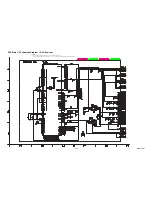
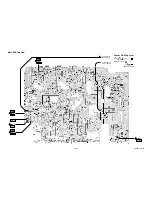
Страница 51: ...SENSOR CBA START SENSOR SW P VR501 CTL TP513 RF SW TP302 WF2 C PB TP301 WF3 V OUT TP751 WF1 TO SENSOR CBA END SENSOR S INH TP502 BE9AB0F01011A Main CBA Top View Sensor CBA Top View BHF300F01012A BHF3...

Страница 52: ...WF12 PIN 11OF TU900 WF13 PIN 12 OF TU900 WF14 PIN 18 OF TU900 WF15 PIN 2 OF IC1406 WF6 PIN 14 OF CN201 PIN 26 OF CN201 WF8 PIN 28 OF CN201 WF7 WF9 PIN 22 OF CN201 WF5 PIN 24 OF CN201 WF4 PIN 28 OF CN2...

Страница 53: ...y circut an isolation transformer must be used Also in order to have the ability to increase the input slowly when troubleshooting this type power supply circuit a variable isolation transformer is re...

Страница 54: ...ly circut an isolation transformer must be used Also in order to have the ability to increase the input slowly when troubleshooting this type power supply circuit a variable isolation transformer is r...

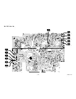
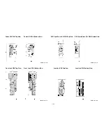
Страница 55: ...Jack CBA Bottom View DVD Open Close SW CBA Top View DVD Open Close SW CBA Bottom View Power SW CBA Top View Power SW CBA Bottom View Junction CBA Top View Junction CBA Bottom View BE9A00F01021B BE9AB...

Страница 56: ...6 Pin 2 of IC1406 VIDEO CVBS 0 5V 20 s WF14 Pin 12 of TU900 WF13 Pin 11 of TU900 WF15 Pin 18 of TU900 NOTE Input COLOR BAR SIGNAL WITH 1KHz AUDIO SIGNAL WF3 WF1 UPPER WF2 WF2 LOWER TP751 TP302 UPPER L...

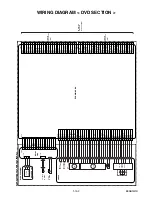
Страница 57: ...ND GND AL 4V NU NU POW P 1 2 3 4 5 6 7 8 9 1 1 2 2 3 4 5 6 1 2 3 4 5 6 7 8 9 10 11 12 1 2 3 4 5 6 7 1 2 3 4 5 6 7 8 9 8 9 3 3 5 9 12 15 1 2 4 6 7 8 10 11 13 14 16 17 18 POWER SUPPLY CBA AC CORD Hi Fi...

Страница 58: ...30 GND 23 P ON 2 5V 24 P ON 2 5V 25 GND 22 GND 26 GND 27 P ON 3 3V 14 P ON 3 3V 15 P ON 3 3V 16 GND 3 GND 2 GND 1 DVD MAIN CBA DVD MECHANISM PICKUP RELAY CBA ENCODER CBA CN201 CN1001 CN1003 10 9 HW 9...

Страница 59: ...0 V 5 00 V CL 0 00 V 0 25 V 0 00 V SB 1 06 V 1 50 V 1 21 V TL 0 66 V 1 05 V 0 91 V FB 1 99 V 2 60 V 2 17 V SF 1 51 V 1 98 V 1 80 V SM 3 20 V 3 75 V 3 40 V AU 0 26 V 0 65 V 0 44 V AL 4 51 V 5 00 V 5 00...

Страница 60: ...e Fig 1 23 RF SW F AD Internal Signal C DRIVE PB CTL 32 C F R 99 H A SW 98 C ROTA The first rise of RF SW after a rise in F AD signal Acceleration Detection T1 AT H Z H L L Stop detection T2 ST Slow T...

Страница 61: ...Internal Signal C DRIVE PB CTL 32 C F R 99 H A SW 98 C ROTA H Z H L L STILL STILL AT ST BL Stop detection T2 Acceleration Detection T1 Slow Tracking Value Reversal Limit Value FRAME ADVANCE The first...

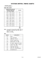
Страница 62: ...EV LD REV LD REV 0 2S 0 5S PIN NO CL EJ SS SS AU AU TL LD SW CL SS LM FWD M REV C DRIVE Z ON ON C F R DRUM ROTATION P ON L A MUTE H D REC H D PB PAUSE SLOW AU AL AL AU SF SM EJ AU RS SF SM TL FB AL SB...

Страница 63: ...EJECT STOP A LD REV FF LD REV LD REV LD FWD LD FWD LD FWD LD FWD LD FWD LD FWD LD FWD REC PAUSE REC REC REW LD REV LD REV LD REV LD REV LD REV LD REV LD REV PAUSE REC or PAUSE STOP EJECT STOP EJECT S...

Страница 64: ...ose Rezero 2 INNER SW open Is Timer ET1 passed INNER SW open Is Timer ET4 passed Is slit S5 passed Is Timer ET3 passed Is Timer ET1 passed Retry OK Is slit S1 passed Is not slit passed Is Timer ET2 pa...

Страница 65: ...0d S1 300 12c T1 0 1 s ET1 5 0 s V1 4 5 V 022 S2 3300 ce4 T2 3 0 s ET2 5 0 s V2 2 2 V 010 S3 3935 f5f T3 3 0 s ET3 3 0 s V3 2 4 V 013 S4 0 000 T4 0 1 s ET4 3 0 s V4 6 0 V 030 S5 3000 bb8 T5 0 1 s SLED...

Страница 66: ...ay close Push close SLED INNER SW Timer close open Tray insertion direction Tray ejection direction S5 V3 V4 S4 ET3 ET4 SLED Encoder pulse S5 T3 V3 V4 ET4 Push Close INNER SW close open Tray insertion...

Страница 67: ...n is pressed after the S5 passage It starts opening after making closing complete once SLED open Tray insertion direction close INNER SW Timer T2 Rezero 1 ET4 V3 V4 SLED INNER SW open Rezero 2 Tray in...

Страница 68: ...etry frequency V1 1st time retry 6 v 2nd time retry 7 v 3rd time retry 8 v 4th time retry 9 v 5th time retry 9 v 6th time retry 9 v SLED Tray ejection direction S1 V1 V2 6v open Tray insertion directi...

Страница 69: ...rding Safety SW Detect With Record tab L Without Record tab H 23 OUT RF SW Video Head Switching Pulse 24 OUT D V SYNC Dummy V sync Output 25 IN RESET System Reset Signal Reset L 26 OUT LM FWD REV Load...

Страница 70: ...ack Record Control Signal 76 OUT CTL Amp Output Control Signal for Test Point 77 NU Not Used 78 IN Hi Fi NOR IN Audio Mode Input HiFi L Normal H 79 IN DVD POWER SAFETY DVD Power Supply Safety Signal P...

Страница 71: ...A Anode K Cathode E Emitter C Collector B Base R Reference S Source G Gate D Drain KRA103M AT P KRC103M AT P KTA1267 Y AT P KTC3193 Y AT P KTC3199 BL Y AT P KTA1266 Y AT P KTC3198 Y AT P KTC3203 Y AT...

Страница 72: ...4 2L044 2L100 2L044 2L062 2L082 A4 A3 D 2B2 2L013 2B3 2L033 2B31 2L033 2L045 2L045 2B19 2B14 A2 2L033 2L033 2L033 C 2L110 2L022 2L021 2L054 2L052 W001 2L017 2L017 2L017 2L017 2L017 2B1 2L014 2L061 2L0...

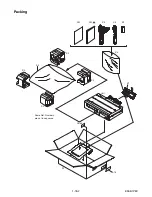
Страница 73: ...1 18 2 E9AB1PEX Packing S1 A14 S2 2B64 S2 S2 Unit S3 Some Ref Numbers are not in sequence X1 X22 X4 X20 X5 X2 X3 S2...

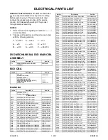
Страница 74: ...MMEZR12NH003 2L011 SCREW TAP TIGHT M3X5 BIND HEAD BLK NI GBHC3050 2L013 SCREW S TIGHT M3X6 BIND HEAD GBJS3060 2L014 SCREW S TIGHT M3X6 BIND HEAD GBJS3060 2L015 SCREW M3X5 HEAD BIND S TIGHT GBJS3050 2...

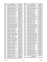
Страница 75: ...03 C320 CERAMIC CAP AX Y M 0 01 F 16V CCA1CMT0Y103 C321 CHIP CERAMIC CAP 1608 B K 0 01 F 50V CHD1JK30B103 C324 CHIP CERAMIC CAP 1608 B K 0 01 F 50V CHD1JK30B103 C327 ELECTROLYTIC CAP 47 F 6 3V M H7 CE...

Страница 76: ...TROLYTIC CAP 1 F 50V M CE1JMASDL1R0 C844 ELECTROLYTIC CAP 10 F 16V M H7 CE1CMAVSL100 C845 CHIP CERAMIC CAP 1608 CH J 1000pF50V CHD1JJ3CH102 Ref No Description Part No C846 ELECTROLYTIC CAP 470 F 6 3V...

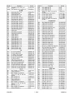
Страница 77: ...1 L771 PCB JUMPER D0 6 P5 0 JW5 0T Ref No Description Part No L800 PCB JUMPER D0 6 P5 0 JW5 0T L801 PCB JUMPER D0 6 P5 0 JW5 0T L900 PCB JUMPER D0 6 P5 0 JW5 0T L901A RADIAL TYPE CHOKE COIL CW68 470K...

Страница 78: ...R5Z0473 R456 CHIP RES 1 10W J 6 8k RRXAJR5Z0682 R457 CHIP RES 1 10W J 470 RRXAJR5Z0471 Ref No Description Part No R458 CHIP RES 1 10W J 3 3k RRXAJR5Z0332 R459 CHIP RES 1 10W J 39k RRXAJR5Z0393 R463 CH...

Страница 79: ...CHIP RES 1 10W J 22k RRXAJR5Z0223 R863 CARBON RES 1 6W J 22k RCX6JATZ0223 R867 CHIP RES 1 10W J 1 5k RRXAJR5Z0152 Ref No Description Part No R868 CHIP RES 1 10W J 1 5k RRXAJR5Z0152 R871 CHIP RES 1 10W...

Страница 80: ...3 Ref No Description Part No Ref No Description Part No FRONT JACK CBA MCV D Consists of the following CONNECTOR CN1605 FE CONNECTOR TOP 8P 08FE BT VK N JCFEJ08JG001 RESISTORS R804 CHIP RES 1 10W J 75...

Страница 81: ...3 3M RXX2JZLZ0335 R016 CHIP RES 1 10W J 1k RRXAJR5Z0102 R017 CHIP RES 1608 1 10W 0 RRXAJR5Z0000 R018 CHIP RES 1 10W J 4 7k RRXAJR5Z0472 R019 CHIP RES 1 10W J 1 8k RRXAJR5Z0182 R020 CHIP RES 1608 1 10...

Страница 82: ...CWV20V6 E9AB1CD 2006 10 6...

Отзывы: