background image

Body conversions

329

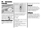
Swinging

The tailboard lower hinges can be

released to allow the tailboard to

swing from its upper hinges during

tipping operations.

9

Warning

To prevent the tailboard becoming

detached from the vehicle, ensure

that the upper hinges are engaged

with the release levers in the

locked position.

Release the lower hinges using the

remote lever located at the rear of the

body. The tailboard is disengaged

and will swing from its upper hinges.
To lock, engage the lower tailboard

hinges and push the remote lever to

the lock position. Check the tailboard

is secure.

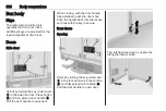
Sideboards

9

Warning

The sideboards are heavy.
Take care when lowering the

sideboards, do not allow them to

drop down unassisted.

To open, pull up the release levers to

disengage the locks. Lower the

sideboard fully.
To close, raise the sideboard and

push firmly into position. Push down

the release levers ensuring locks

engage fully.

Содержание Movano

Страница 1: ...Owner s Manual ...

Страница 2: ......

Страница 3: ...straints 45 Storage 73 Instruments and controls 84 Lighting 110 Infotainment system 118 Climate control 208 Driving and operating 224 Vehicle care 268 Service and maintenance 311 Technical data 315 Customer information 319 Body conversions 327 Index 342 Contents ...

Страница 4: ...2 Introduction Introduction ...

Страница 5: ...rs provide first class service at reasonable prices Experienced mechanics trained by Opel work according to specific Opel instructions The customer literature pack should always be kept ready to hand in the vehicle Using this manual This manual describes all options and features available for this model Certain descriptions including those for display and menu functions may not apply to your vehic...

Страница 6: ...accident or injury Disregarding this information may lead to injury Caution Text marked Caution provides information on possible damage to the vehicle Disregarding this information may lead to vehicle damage Symbols Page references are indicated with 3 3 means see page Page references and index entries refer to the indented headings given in the section table of content We wish you many hours of p...

Страница 7: ...Introduction 5 ...

Страница 8: ...ng the handles Unlocking with remote control Depending on vehicle configuration Press c to unlock the front doors Press again to unlock entire vehicle Open the doors by pulling the handles With 3 button remote control press G Only the load compartment is unlocked Radio remote control 3 21 Central locking system 3 24 Anti theft alarm system 3 36 ...

Страница 9: ...nt and pull the handle to open Electronic key system 3 22 Seat adjustment Longitudinal adjustment Pull handle slide seat release handle Try to move the seat back and forth to ensure that the seat is locked in place Seat position 3 46 Seat adjustment 3 47 Backrests inclination Pull lever adjust inclination and release lever Allow the seat to engage audibly Seat position 3 46 Seat adjustment 3 47 ...

Страница 10: ...se button adjust height engage Head restraints 3 45 Seat belt Pull out the seat belt and fasten in belt buckle The seat belt must not be twisted and must fit close against the body The backrest must not be tilted back too far maximum approx 25 To unfasten belt press red button on belt buckle Seat position 3 46 Seat belts 3 55 Airbag system 3 59 ...

Страница 11: ...ew mirror 3 40 Rear view display 3 40 Exterior mirrors Manual adjustment Swivel mirror in required direction Exterior mirrors 3 38 Electric adjustment Select the relevant exterior mirror and adjust it by swivelling the control Convex exterior mirrors 3 38 Electric adjustment 3 39 Folding exterior mirrors 3 39 Heated exterior mirrors 3 39 ...

Страница 12: ...stment Unlock lever adjust steering wheel then engage lever and ensure it is fully locked Do not adjust steering wheel unless vehicle is stationary and steering wheel lock has been released Airbag system 3 59 Ignition positions 3 226 ...

Страница 13: ...In brief 11 Instrument panel overview ...

Страница 14: ...4 11 Tray 73 12 Glovebox 74 13 Parking assist 255 Lane departure warning 261 Electronic Stability Control and Traction Control 247 Hazard warning flashers 113 Central locking system 24 Stop start system 228 Side blind spot alert 257 ECO mode 225 14 Inductive charging 90 15 Climate control system 208 16 Power outlet 88 17 Cruise control 249 Speed limiter 251 18 Manual transmission 241 Manual transm...

Страница 15: ...In brief 13 ...

Страница 16: ...lights are switched on and off automatically Lighting 3 110 Automatic light control 3 110 Headlight warning device 3 107 Front fog lights 3 113 Rear fog light 3 114 Headlight flash high beam and low beam Pull lever High beam 3 111 Headlight flash 3 112 Turn lights up right turn light down left turn light Turn lights 3 113 ...

Страница 17: ... by pressing Hazard warning flashers 3 113 Horn Press j Horn 3 85 Washer and wiper systems Windscreen wiper 0 off P AUTO timed interval wiping or automatic wiping with rain sensor 1 slow 2 fast Windscreen wiper 3 86 Wiper blade replacement 3 277 ...

Страница 18: ...ing is operated by pressing Ü Heated rear window 3 43 Heated exterior mirrors Pressing Ü also activates the heated exterior mirrors Heated exterior mirrors 3 39 Demisting and defrosting the windows Climate control system Switch cooling A C on if available Set temperature control to warmest level Set fan speed to highest level Set air distribution control to V Switch on heated rear window Ü Open si...

Страница 19: ...epress clutch pedal and then pull up the collar on the selector lever and engage the gear If the gear does not engage set the lever to neutral release the clutch pedal and depress again then repeat gear selection Manual transmission 3 241 Manual transmission automated N neutral o drive position higher gear lower gear D M switch between automatic and manual mode R reverse gear Engage only when vehi...

Страница 20: ...ing and wait until control indicator extinguishes in the Driver Information Centre Turn key to position 3 and release Starting the engine 3 227 Stop start system An Autostop is indicated when control indicator Ï illuminates in the Driver Information Centre Manual transmission If the vehicle is at low speed or in standstill and certain conditions are fulfilled activate an Autostop as follows depres...

Страница 21: ...ge first gear On an uphill slope turn the front wheels away from the kerb If the vehicle is on a downhill slope engage reverse gear Turn the front wheels towards the kerb Close the windows Remove the ignition key from the ignition switch Turn the steering wheel until the steering wheel lock is felt to engage Lock the vehicle by pressing e on the remote control 3 24 Activate the anti theft alarm sy...

Страница 22: ...ed mirrors 39 Interior mirrors 40 Manual anti dazzle 40 Rear view display 40 Windows 41 Windscreen 41 Manual windows 41 Power windows 41 Rear windows 42 Heated rear window 43 Sun visors 43 Roof 44 Glass panel 44 Keys locks Keys Caution Do not attach heavy or bulky items to the ignition key Replacement keys The key number is specified in the Car Pass or on a detachable tag The key number must be qu...

Страница 23: ...e with care protect it from moisture and high temperatures and avoid unnecessary operation Fault If the central locking system cannot be operated with the remote control it may be due to the following The range is exceeded The battery voltage is too low Frequent repeated operation of the remote control while not in range which will require reprogramming by a workshop Overload of the central lockin...

Страница 24: ...e driver s person Note Always take the electronic key with you when exiting the vehicle For hands free operation the electronic key must be outside the vehicle within a range of approx 1 m of the front doors or load compartment Hands free operation is automatically disabled when the central locking switch e 3 24 is pressed To re enable hands free operation restart the engine Electronic key battery...

Страница 25: ... of the central locking system by operating at frequent intervals the power supply is interrupted for a short time interference from higher power radio waves from other sources Door locks Anti theft security lock To prevent the front doors from being opened from the outside open the door and engage the anti theft security lock Using a suitable tool turn the lock switch on the door to the horizonta...

Страница 26: ...mote control the front doors and load compartment and depending on vehicle configuration the sliding side doors can be unlocked and locked separately Note A short time after unlocking with the remote control the doors are locked automatically if no door has been opened Unlocking the vehicle Operation of central locking system with the remote control is confirmed by the hazard warning flashers The ...

Страница 27: ...load compartment When locking if a door is open or incorrectly closed the central locking system will lock and unlock in quick succession without flashing the hazard warning flashers Locking with 2 button remote control Press e All doors and the load compartment are locked Locking with 3 button remote control Press e All doors and the load compartment are locked Note Where fitted alarm monitoring ...

Страница 28: ...artment is locked or unlocked Press G Load compartment and sliding side doors are locked or unlocked Electronic key system operation For hands free operation the electronic key must be outside the vehicle within a range of approx 1 m of the front doors or load compartment Note There is no button for hands free operation in the exterior door handle of the sliding side door There must be no electron...

Страница 29: ...ree operation Locking with electronic key hands free operation Press the button on any exterior door handle All doors and the load compartment are locked The vehicle only locks when at least 3 seconds have passed since unlocking using hands free operation Load compartment locking and unlocking with electronic key hands free operation Press the button on the exterior door handle to lock or unlock t...

Страница 30: ...y turning the key in the lock Switch on the ignition and press the central locking switch e to open all doors and the load compartment Locking Manually lock the front door by turning the key in the lock Fault in central locking system Unlocking Manually unlock the front door by turning the key in the lock The other doors can be opened by pulling the interior handles Locking Using a key or suitable...

Страница 31: ...Automatic locking after driving off Depending on version this security feature can be configured to automatically lock all doors and the load compartment as soon as the vehicle is driven Activation With the ignition switched on press and hold the central locking switch e for approx 5 seconds An audible signal confirms activation LED in switch illuminates when the vehicle is locked Deactivation Wit...

Страница 32: ... Warning Take care when operating the sliding side door Risk of injury Ensure that nothing becomes trapped during operation and no one is standing within the moving area If the vehicle is parked on a slope open sliding doors may move accidentally on account of their weight Close the sliding doors before driving off 9 Danger Do not drive with the sliding side door open or ajar e g when transporting...

Страница 33: ...D flashes and a chime sounds during operation In the event of opening or closing difficulties e g due to frost press and hold the switch to increase power to the sliding door 9 Warning Take care when operating the power sliding door Risk of injury particularly to children Take particular care when the vehicle is parked on a slope open or close the door fully until it latches into its locking posit...

Страница 34: ...uator motor operates then press and hold the switch on the instrument panel to fully close the door The warning light extinguishes when the system is reset correctly Maintenance The counter is incremented at each opening and closing to determine the replacement of the drive belt Seek the assistance of a workshop If the drive belt should fail the door may still be opened and closed manually Fault I...

Страница 35: ... latched into its locking position In the event of a failure manually retract the power side step by unscrewing the orange handwheel located at the rear of the step ensuring that there are no obstacles preventing closure When the step is retracted screw in the orange handwheel Seek the assistance of a workshop Rear doors Lock and unlock the rear doors with the remote control or key if equipped Cen...

Страница 36: ...rs are retained in the 90º position by locking stays To open the doors to 180º or further depending on model release locking stays from the catches on the door frames and lock in place Swing doors open to the desired position When opening the doors to 270º the doors are retained in the fully open position by magnets on the body side 9 Warning Ensure extended opening doors are secured when fully op...

Страница 37: ...toxic exhaust gases which cannot be seen or smelled could enter the vehicle This can cause unconsciousness and even death Vehicle security Anti theft locking system 9 Warning Do not use the system if there are people in the vehicle The doors cannot be unlocked from the inside The system deadlocks the doors All doors must be closed or the system cannot be activated Note The anti theft locking syste...

Страница 38: ...locking system 3 24 Electronic key system 3 22 Anti theft alarm system The anti theft alarm system is operated in conjunction with the central locking system It monitors doors bonnet passenger compartment load compartment ignition interruption of alarm siren power supply Activation All doors and the bonnet must be closed Press e to activate anti theft alarm system Hazard warning lights flash twice...

Страница 39: ...oring of the passenger compartment when people or animals are being left in the vehicle or if the auxiliary heater 3 216 is set for a timed or remote controlled start Depending on vehicle configuration press and hold e or switch ignition on and off twice quickly then close doors and activate the anti theft alarm system An audible signal will sound as confirmation The status will remain until the d...

Страница 40: ...t the start attempt If start attempt is unsuccessful attempt to start the engine using the spare key and seek the assistance of a workshop Note Radio Frequency Identification RFID tags may cause interference with the key Do not have it placed near the key when starting the vehicle Note The immobiliser does not lock the doors Always lock the vehicle after leaving it 3 24 and switch on the anti thef...

Страница 41: ...out of their normal mounting position if they are struck with sufficient force Reposition the mirror by applying slight pressure to the mirror housing Parking position The exterior mirrors can be folded in by pressing gently on the outer edge of the housing e g when in a confined parking situation Heated mirrors Operated by pressing Ü on either system LED illuminates in button during operation Hea...

Страница 42: ...enger sun visor which helps to increase visibility and reduce blind spots Rear view display The rear view display shows the standard rear view provided by a camera mounted on top of the rear end The mounting position and view angle of the camera cause a blind spot area behind the vehicle While reverse gear is engaged the rear view display is switched off Adjustment Press to adjust brightness by us...

Страница 43: ...therwise the detection zone of the sensor in the mirror housing could be restricted Windscreen replacement Caution If the vehicle has a front looking camera sensor for the driver assistance systems it is very important that any windscreen replacement is performed accurately according to Opel specifications Otherwise these systems may not work properly and there is a risk of unexpected behaviour an...

Страница 44: ...ent In the event of closing difficulties due to frost or the like operate the switch several times to close the window in stages Overload If the windows are repeatedly operated within short intervals the window operation is disabled for some time Rear windows Sliding side windows Press catch and slide window to open Ensure catch engages when closing Press catch and slide window to open Ensure catc...

Страница 45: ...sists the driver when reversing by reducing blind spots Heated rear window Operated by pressing Ü on either system LED illuminates in button during operation Heating works with the engine running and is switched off automatically after a short time Climate control system 3 208 Electronic climate control system 3 210 Sun visors The sun visors can be folded down or swivelled to the side to prevent d...

Страница 46: ...iant the load compartment may incorporate a single or a double glass roof panel Emergency exit In an emergency the glass can be broken Use the hammer provided to strike the glass panel Depending on version emergency exit may alternatively be via the side windows 3 42 ...

Страница 47: ...ild restraints 65 Child restraint systems 65 Child restraint installation locations 67 Head restraints Position 9 Warning Only drive with the head restraint set to the proper position The upper edge of the head restraint should be at upper head level If this is not possible for extremely tall people set to highest position and set to lowest position for small people Adjustment Pull up to raise or ...

Страница 48: ...ts securely in load compartment Do not drive with head restraints removed if the seat is occupied Installation First tilt the backrest forwards then insert the rods of the head restraint into their holes Lower head restraint as far as possible then raise head restraint press both release buttons first if necessary until it engages securely in desired position Front seats Seat position 9 Warning On...

Страница 49: ...ake so that it is possible to reach the steering wheel with arms slightly bent Maintain contact between shoulders and the backrest when turning the steering wheel Do not angle the backrest too far back We recommend a maximum rake of approx 25 Adjust seat and steering wheel in a way that the wrist rests on top of the steering wheel while the arm is fully extended and shoulders on the backrest Adjus...

Страница 50: ... Try to move the seat back and forth to ensure that the seat is locked in place Backrest inclination Pull lever adjust inclination and release lever Allow the seat to engage audibly Suspension seat backrest inclination Pull lever adjust inclination and release lever Allow the seat to engage audibly ...

Страница 51: ...height Pull up front release lever up to adjust height of front part of seat Pull up rear release lever to adjust height of rear part of seat Lumbar support Adjust lumbar support to suit personal requirements Increasing and decreasing support turn the handwheel while relieving the load on the backrest ...

Страница 52: ...s Suspension seat sensitivity Rotate knob to adjust the sensitivity of the suspension seat turn right more stiff turn left less stiff Swivel seat adjustment Seat positioning Move handle 2 slide seat release handle Try to move the seat back and forth to ensure that the seat is locked in place Seat backrests Pull lever 1 adjust inclination and release lever Allow the seat to engage audibly Seat base...

Страница 53: ...the forward facing position e g for easier access to the load compartment area when the vehicle is stationary and the engine is switched off Before swivelling the seat make the following preparations Unfasten seat belt Fold up the armrests Slide seat as far back as possible Set seat base angle to its lowest position Adjust backrest inclination to vertical position Open the driver s door Lift handl...

Страница 54: ...witches off automatically when seat temperature is sufficient LED also illuminates when the system is on not just when heating is active Prolonged use for people with sensitive skin is not recommended Seat heating is operational when the engine is running Rear seats Rear seat access To facilitate access to the 3rd row seats where fitted open sliding side door and pull release lever on folding acce...

Страница 55: ...rear seats Removal On some variants the load compartment area can be increased by removing the rear seats 9 Warning Removable rear seats are heavy Do not attempt to remove without assistance Pull up lever 1 on both sides of the seat The pins 2 visibly protrude to indicate that the seat is unlocked Move the seat towards the rear to release from the floor anchor points Lift seat to remove Installati...

Страница 56: ...o longer be visible to indicate that the seat is locked Caution When installing the rear seats ensure they are properly located on the floor anchor points and that the locking catches are fully engaged Consult a workshop if the seats cannot be locked securely in position Bus Removal 9 Warning Removable rear seats are heavy Do not attempt to remove without assistance Using the tool from the tool ki...

Страница 57: ...ing the occupants in the sitting position Therefore the risk of injury is considerably reduced 9 Warning Fasten seat belt before each trip In the event of an accident people not wearing seat belts endanger their fellow occupants and themselves Seat belts are designed to be used by only one person at a time Child restraint system 3 65 Periodically check all parts of the belt system for damage and p...

Страница 58: ...jects that may interfere with the operation of the belt pretensioners Do not make any modifications to belt pretensioner components as this will invalidate the vehicle operating permit Three point seat belt Seat belts on the front seats Fasten Withdraw the belt from the retractor guide it untwisted across the body and insert the latch plate into the buckle Tighten the lap belt regularly whilst dri...

Страница 59: ...press button to disengage and push the height adjustment downwards Adjust the height so that the belt lies across the shoulder It must not lie across the throat or upper arm 9 Warning Do not adjust while driving Unfasten To unfasten belt press red button on belt buckle The seat belt retracts automatically ...

Страница 60: ...ng lap belt 5 Loose or bulky clothing prevents the belt from fitting snugly Do not place objects such as handbags or mobile phones between the belt and your body 9 Warning The belt must not rest against hard or fragile objects in the pockets of your clothing To unfasten press red button on belt buckle 3 to release the latch plate 2 Guide the seat belt 1 as it retracts automatically 9 Warning Ensur...

Страница 61: ...king properly The operation of the airbag system can also be affected by changing any parts of the front seats seat belts airbag sensing and diagnostic module steering wheel instrument panel inner door seals including the speakers any of the airbag modules ceiling or pillar trim front sensors side impact sensors or airbag wiring Note The airbag systems and belt pretensioner control electronics are...

Страница 62: ... retención infantil orientado hacia atrás en un asiento protegido por un AIRBAG FRONTAL ACTIVO Peligro de MUERTE o LESIONES GRAVES para el NIÑO RU ЗАПРЕЩАЕТСЯ устанавливать детское удерживающее устройство лицом назад на сиденье автомобиля оборудованном фронтальной подушкой безопасности если ПОДУШКА НЕ ОТКЛЮЧЕНА Это может привести к СМЕРТИ или СЕРЬЕЗНЫМ ТРАВМАМ РЕБЕНКА NL Gebruik NOOIT een achterwa...

Страница 63: ...И не використовуйте систему безпеки для дітей що встановлюється обличчям назад на сидінні з УВІМКНЕНОЮ ПОДУШКОЮ БЕЗПЕКИ інакше це може призвести до СМЕРТІ чи СЕРЙОЗНОГО ТРАВМУВАННЯ ДИТИНИ HU SOHA ne használjon hátrafelé néző biztonsági gyerekülést előlről AKTÍV LÉGZSÁKKAL védett ülésen mert a GYERMEK HALÁLÁT vagy KOMOLY SÉRÜLÉSÉT okozhatja HR NIKADA nemojte koristiti sustav zadržavanja za djecu ok...

Страница 64: ...ĒRNS var gūt SMAGAS TRAUMAS vai IET BOJĀ ET ÄRGE kasutage tahapoole suunatud lapseturvaistet istmel mille ees on AKTIIVSE TURVAPADJAGA kaitstud iste sest see võib põhjustada LAPSE SURMA või TÕSISE VIGASTUSE MT QATT tuża trażżin għat tfal li jħares lejn in naħa ta wara fuq sit protett b AIRBAG ATTIV quddiemu dan jista jikkawża l MEWT jew ĠRIEĦI SERJI lit TFAL GA Ná húsáid srian sábháilteachta linbh...

Страница 65: ...eat backrest This can be identified by the word AIRBAG The side airbag system is triggered in the event of an accident of a certain severity The ignition must be switched on The inflated airbags cushion the impact thereby reducing the risk of injury to the upper body and pelvis in the event of a side on collision considerably 9 Warning Keep the area in which the airbag inflates clear of obstructio...

Страница 66: ...stem subject to the instructions and restrictions in the table 3 67 Otherwise there is a risk of fatal injury for a person occupying a seat with a deactivated front passenger airbag As long as control indicator Ó is illuminated the airbag systems for the front passenger seat will inflate in the event of a collision If control indicator j remains illuminated together with v this indicates a fault w...

Страница 67: ... regulations In some countries the use of child restraint systems is forbidden on certain seats Child restraint systems can be fastened with Three point seat belt ISOFIX brackets Top Tether Three point seat belt Child restraint systems can be fastened by using a three point seat belt 3 56 Depending on the size of the used child restraint systems and the model variant child restraint systems can be...

Страница 68: ...cident Suitable are restraint systems that comply with valid UN ECE regulations Check local laws and regulations for mandatory use of child restraint systems Ensure that the child restraint system to be installed is compatible with the vehicle type Ensure that the mounting location of the child restraint system within the vehicle is correct see following tables Allow children to enter and exit the...

Страница 69: ...hout airbag with airbag centre outer centre outer Group 0 up to 10 kg Group 0 up to 13 kg U U2 U U U2 U2 Group I 9 to 18 kg U U2 U U U2 U2 Group II 15 to 25 kg Group III 22 to 36 kg U U2 U U U2 U2 1 If adjustable ensure seat is in its rearmost position Make sure vehicle seat belt is as straight as possible between shoulder and upper anchorage point 2 Ensure the front passenger airbag system is dea...

Страница 70: ...68 Seats restraints Crew van rear seats Weight and age class 2nd row seats Outer Centre Group 0 up to 10 kg Group 0 up to 13 kg U X Group I 9 to 18 kg U X Group II 15 to 25 kg Group III 22 to 36 kg U X ...

Страница 71: ...acing child seat then move back the seat in front in accordance with the child seat instructions 4 Forward facing child seat position the seatback of the child seat in contact with the seatback of the vehicle seat Adjust the height of the headrest or remove it if necessary do not push the seat in front of the child more than halfway back on its runners and do not recline the seatback more than 25 ...

Страница 72: ...point seat belt UF suitable for universal category forward facing restraint systems for use in this weight and age class in conjunction with three point seat belt suitable for ISOFIX child restraint system with mounting brackets and anchorage points where fitted When mounting an ISOFIX child restraint system only systems that have been approved for the vehicle may be used Refer to Permissible opti...

Страница 73: ... IL X X X Group I 9 to 18 kg D ISO R2 X IL X X X C ISO R3 X IL X X X B ISO F2 X IL IUF IL IUF X X B1 ISO F2X X IL IUF IL IUF X X A ISO F3 X IL IUF IL IUF X X IL suitable for particular ISOFIX restraint systems of the specific vehicle restricted or semi universal categories The ISOFIX restraint system must be approved for the specific vehicle type IUF suitable for ISOFIX forward facing child restra...

Страница 74: ... in the weight class 9 to 18 kg B1 ISO F2X forward facing child restraint system for smaller children in the weight class 9 to 18 kg C ISO R3 rear facing child restraint system for children of maximum size in the weight class up to 18 kg D ISO R2 rear facing child restraint system for smaller children in the weight class up to 18 kg E ISO R1 rear facing child restraint system for young children in...

Страница 75: ... 9 Warning Do not store heavy or sharp objects in the storage compartments Otherwise vehicle occupants could be injured by objects being thrown around in the event of hard braking a sudden change in direction or an accident Instrument panel storage Storage compartments pockets and trays are located in the instrument panel Storage compartments can be located on top of the instrument panel Document ...

Страница 76: ...holders are located at either end of the instrument panel and centrally in the lower instrument panel Press at the front to open Additionally cupholders may be located in the rear side of the front centre passenger seat Folding passenger seatback 3 74 Depending on model cupholders may also be located in the lower front part of the rear seats The cupholders can also be used to hold the portable ash...

Страница 77: ...de of the backrest features storage compartments cupholders and a swivelling shelf which can be used for writing or documents Return the swivelling shelf to its original position before pulling backrest release lever and raising the backrest Overhead console The total weight in these compartments must not exceed 5 kg Underseat storage Using the two loops on the passenger seat cushion pull the cush...

Страница 78: ...nt must not exceed 35 kg Rear storage Combi Bus Objects can be stored in the overhead storage compartments above the rear passenger seats The total weight must not exceed 20 kg evenly distributed Load compartment 9 Warning Always make sure that the load in the vehicle is securely stowed Otherwise objects can be thrown around inside the vehicle and cause personal injury or damage to the load or veh...

Страница 79: ... and or in the sidewall The number and location of the lashing eyes may vary depending on the vehicle The maximum force applied to the lashing eyes should not exceed 625 daN 6 25 kN 6250 N Depending on country the maximum force e g 500 daN 5 kN 5000 N may be shown on a label Note Specifications on the label always have priority over those given in this manual Loading information 3 82 Removable las...

Страница 80: ...y by attaching the appropriate cargo management feature to the side floor or roof load rails using removable lashing eyes if required Lower and also upper side load rails may be present depending on version Moveable partition wall The moveable partition wall can be used between the floor and roof load rails To move pull down on the latch to release and position the wall as required Ensure the latc...

Страница 81: ...ty net The blocking bar can be secured to the upper side load rails rotate handle to fix blocking bar into position Ensure blocking bar engages fully The integrated safety net can then be attached to the removable lashing eyes in the side and floor load rails see illustration Ratchet straps Using the appropriate ratchet straps objects can be secured in position using the removable lashing eyes in ...

Страница 82: ...he vehicle floor 3 77 Adjust the tension on the straps to ensure the load is secure When not in use the safety net should be stored in the roof area Loading information 3 82 Load compartment grille Vehicles with a window in the cabin bulkhead may include a metal grille on the load compartment side The grille provides protection from load compartment objects being thrown around in the event of hard...

Страница 83: ...cushion pull the cushion forwards to gain access Underseat storage 3 75 Depending on version the first aid kit may alternatively be located in the space between the front seats or in the overhead console Fire extinguisher As a visible indication of the presence of a fire extinguisher a label may be located on the overhead console 3 75 The fire extinguisher can be accommodated in the space under th...

Страница 84: ...ure loose objects in load compartment to prevent them from sliding The load must not obstruct the operation of the pedals parking brake and gear selector lever or hinder the freedom of movement of the driver Do not place any unsecured objects in the interior Do not drive with an open load compartment In addition the number plate is only distinguishable and illuminated correctly if the doors are cl...

Страница 85: ...ng due to the vehicle s higher centre of gravity Distribute the load evenly and secure it properly with retaining straps Adjust the tyre pressure and vehicle speed according to the load conditions Check and retighten the straps frequently Do not drive faster than 120 km h The permissible roof load which includes the weight of the roof rack is 200 kg for standard roof variants The roof load is the ...

Страница 86: ...nsioners 98 Airbag deactivation 98 Charging system 99 Malfunction indicator light 99 Service vehicle soon 99 Stop engine 100 Brake system 100 Parking brake 100 Antilock brake system ABS 100 Gear shifting 100 Variable effort steering 100 Lane departure warning 101 Electronic Stability Control 101 Engine coolant temperature 101 Preheating 101 AdBlue 101 Tyre pressure monitoring system 102 Engine oil...

Страница 87: ...l lock has been released Steering wheel controls The cruise control and speed limiter can be operated via the controls on the steering wheel Cruise control 3 249 Speed limiter 3 251 Horn Press j The horn will sound regardless of ignition switch position Steering column controls The Infotainment system can also be operated via the controls on the steering column Further information is available in ...

Страница 88: ...en moved Adjustable delay of timed interval wiping P timed interval wiping Turn the adjuster wheel to adjust the delay between wipes longer delay turn adjuster wheel downwards shorter delay turn adjuster wheel upwards Automatic wiping with rain sensor AUTO automatic wiping with rain sensor The rain sensor detects the amount of water on the windscreen and automatically regulates the frequency of th...

Страница 89: ...Pull lever Washer fluid is sprayed onto the windscreen short pull wiper swipes once long pull wiper swipes for a few strokes Outside temperature The outside temperature is displayed in the Driver Information Centre or in the Info Display A drop in temperature is indicated immediately and a rise in temperature after a time delay If outside temperatures is 3 C to 3 C the C flashes in the display as ...

Страница 90: ...lay Further information is available in the Infotainment manual Set time in Driver Information Centre Display the clock function by pressing button repeatedly on end of wiper lever Press and hold one of the buttons until hours flash Press or hold one of the buttons to set the hour Wait until minutes flash Press or hold one of the buttons to set the minute Wait before selecting another function Pow...

Страница 91: ...st not exceed 180 W With ignition off the power outlet may be deactivated Additionally the power outlet may be deactivated in case of low battery voltage Electrical accessories that are connected must comply with the electromagnetic compatibility requirements laid down in DIN VDE 40 839 Caution Do not connect any current delivering accessories e g electrical charging devices or batteries Do not da...

Страница 92: ...very hot To charge a device the ignition must be switched on To charge a mobile device 1 Remove all objects from the charging device 2 Place the mobile device with the display facing upwards on the charging device in the storage Charging status may be indicated in the Info Display PMA or Qi compatible mobile devices can be charged inductively On some mobile devices a back cover with an integrated ...

Страница 93: ...ash and not for combustible rubbish Portable ashtray Ashtray container for mobile use in the vehicle To use open cover Warning lights gauges and indicators Instrument cluster In some versions the needles of the instruments briefly rotate to the end position when the ignition is switched on Speedometer Indicates vehicle speed Speed warning 3 104 Speed limiter 3 251 Cruise control 3 249 ...

Страница 94: ...lays the distance travelled since the last reset To reset with the trip odometer displayed press and hold one of the buttons on end of wiper lever until the value resets to 0 Trip computer 3 108 Tachometer Displays the engine speed Drive in a low engine speed range for each gear as much as possible Caution If the needle is in the red warning zone the maximum permitted engine speed is exceeded Engi...

Страница 95: ...dBlue gauge shows the current AdBlue fluid level remaining in the tank Control indicator ú 3 101 illuminates and a warning chime sounds if the level in the tank is low Refill AdBlue as soon as possible to avoid prevention of engine starts AdBlue 3 234 Engine coolant temperature gauge Displays the coolant temperature left area engine operating temperature not yet reached central area normal operati...

Страница 96: ... service will be indicated can vary considerably When the remaining distance before the next service is less than 1500 km or 1 month a message appears in the Driver Information Centre When the distance reaches 0 km or the service date is due control indicator j illuminates and a message appears in the Driver Information Centre The vehicle needs a service Seek the assistance of a workshop Resetting...

Страница 97: ...ding on the equipment the position of the control indicators may vary When the ignition is switched on most control indicators will illuminate briefly as a functionality test The control indicator colours mean red danger important reminder yellow warning information fault green confirmation of activation blue confirmation of activation white confirmation of activation ...

Страница 98: ...96 Instruments and controls Control indicators in the instrument cluster ...

Страница 99: ...effort steering 3 100 Q Lane departure warning 3 101 R Electronic Stability Control 3 101 W Engine coolant temperature 3 101 Preheating 3 101 ú AdBlue 3 101 w Tyre pressure monitoring system 3 102 I Engine oil pressure 3 102 Y Low fuel 3 103 D Autostop Stop start system 3 103 Autostop inhibited Stop start system 3 103 F Exterior light 3 103 9 Low beam 3 103 C High beam 3 103 f High beam assist 3 1...

Страница 100: ... before each trip In the event of an accident people not wearing seat belts endanger their fellow occupants and themselves Three point seat belts 3 56 Airbag and belt tensioners v illuminates yellow When the ignition is switched on the control indicator illuminates briefly If it does not illuminate or illuminates whilst driving there is a fault in the airbag system Seek the assistance of a worksho...

Страница 101: ...briefly when the ignition is switched on Illuminates when the engine is running Fault in the emission control system The permitted emission limits may be exceeded Seek the assistance of a workshop immediately If Z illuminates in combination with A stop vehicle and switch off engine as soon as possible 9 Warning Have the cause of the fault remedied immediately by a workshop Flashes when the engine ...

Страница 102: ...ey Consult a workshop Brake system 3 244 Parking brake j illuminates red Control indicator j remains illuminated when the parking brake is applied and extinguishes when the parking brake is released 3 245 Antilock brake system ABS u illuminates yellow Illuminates briefly when the ignition is switched on The system is ready for operation when u extinguishes Illuminates during driving when there is ...

Страница 103: ...uced and the vehicle may be braked automatically to a small degree 3 248 Illuminates during driving The system is unavailable May illuminate together with control indicator j 3 99 A corresponding message also appears in the Driver Information Centre 3 105 ESC 3 248 Traction Control system 3 247 Engine coolant temperature W illuminates blue or red Illuminates briefly blue when the ignition is switc...

Страница 104: ...nding message appears in the Driver Information Centre when a puncture or severely under inflated tyre is detected Flashes Fault in system After a delay the control indicator illuminates continuously Consult a workshop Control indicator w illuminates together with j 3 99 and a corresponding message appears in the Driver Information Centre when a tyre without a pressure sensor is mounted e g spare ...

Страница 105: ...converter 3 234 Bleeding the diesel fuel system 3 276 Stop start system illuminates when an Autostop is inhibited when certain conditions are not fulfilled Ï illuminates during an Autostop Ï flashes if the clutch is not released sufficiently Stop start system 3 228 Exterior light F illuminates green Illuminated when the side lights are on 3 110 Low beam 9 illuminates or flashes green Illuminates I...

Страница 106: ...derately or hard Active emergency braking 3 253 Speed warning Depending on vehicle and country is displayed as long as the speed is over a set value Limited speed Depending on version and country the maximum speed is set by default A warning chime will sound for 10 seconds if the vehicle briefly exceeds the set limit Note Under certain conditions e g steep inclines the vehicle speed may exceed the...

Страница 107: ...braking 3 253 Some of the displayed functions differ when the vehicle is being driven or at a standstill Some functions are only available when the vehicle is being driven Info Display The central display in the Infotainment system displays the time and or outside temperature depending on version and Infotainment system information Press X to switch the Infotainment system on Alternatively it auto...

Страница 108: ...neys can be saved in the system memory enabling to compare performances Refer to Infotainment manual for further information Vehicle messages Messages are indicated in the Driver Information Centre in some cases together with a warning chime The vehicle messages are displayed as text Follow the instructions given in the messages Fault messages Displayed in combination with control indicator j Driv...

Страница 109: ...ion 3 36 If the AdBlue level falls below a certain amount or a fault is present 3 234 If the lane departure warning system detects an unintended lane change and when the system is activated 3 261 When the vehicle is parked and or the driver s door is opened When the key is in the ignition switch With exterior lights on 3 110 There is a fault with the power door lock system 3 28 If the vehicle has ...

Страница 110: ... Instantaneous fuel consumption The value is displayed after reaching a speed of 20 km h Fuel range The value is displayed after driving a distance of 400 m The fuel range is calculated from the current contents of the fuel tank and the average fuel consumption since the last reset The fuel range will not display if control indicator Y is illuminated 3 103 Distance travelled Displays the distance ...

Страница 111: ... The AdBlue range is calculated from the current contents of the AdBlue tank and the average AdBlue consumption 3 234 Interruption of power supply If the power supply has been interrupted or if the vehicle battery voltage has dropped too low the values stored in the trip computer will be lost Tachograph The tachograph is operated as described in the operating instructions supplied Observe regulati...

Страница 112: ...harge protection 117 Exterior lighting Light switch Turn outer light switch 7 off 0 sidelights 9 P headlights AUTO automatic light control headlights are switched on and off automatically Sidelights control indicator F 3 103 Low beam control indicator 9 3 103 High beam control indicator P 3 103 Side position lights Side position lights are illuminated together with sidelights Automatic light contr...

Страница 113: ...no restrictions detected the system switches back to high beam Activation Turn the outer light switch to AUTO then pull the lever to activate high beam assist The control indicator f illuminates continuously in the instrument cluster when the assist is activated while the blue control indicator 7 3 103 illuminates when high beam is on Control indicator f 3 103 Note Use of the system does not relie...

Страница 114: ...ht range adjustment With low beam switched on adapt the headlight range to suit the vehicle load to prevent dazzling of oncoming traffic Turn knurled wheel to proposed position 0 driver only 2 front seats occupied and loaded up to permissible maximum weight 3 driver only and loaded up to permissible maximum weight Headlights when driving abroad The asymmetrical headlight beam extends visibility at...

Страница 115: ...rd warning flashers may turn on automatically Switch off by pressing Turn lights up right turn light down left turn light A resistance point can be felt when moving the lever Constant flashing is activated when the lever is being moved beyond the resistance point It is deactivated when the steering wheel is moved in the opposite direction or lever is manually moved back to its neutral position Act...

Страница 116: ...ide of the light covers may mist up briefly in poor wet and cold weather conditions in heavy rain or after washing The mist disappears quickly by itself To help switch on the headlights Interior lighting Interior lights Courtesy lights illuminate when the vehicle is unlocked with the remote control or the front doors are opened When the doors are closed the courtesy light extinguishes after a dela...

Страница 117: ...de and rear doors are opened or switched on constantly With the switch in its central position the light functions as a courtesy light operated by pressing the left side of the switch on constantly operated by pressing the right side of the switch off constantly Operated by pressing the switch c on constantly on when the doors are unlocked and opened off constantly When the doors are closed the co...

Страница 118: ...ually and directed as required press I on press 0 off Courtesy lights 3 114 Lighting features Exit lighting Headlights come on for approx 30 seconds after the vehicle is parked and the system is activated Activating 1 Switch off ignition 2 Light switch in position 7 or AUTO 3 Pull lever towards steering wheel This action can be repeated up to four times ...

Страница 119: ...ely by turning the light switch to any position and returning to 7 or AUTO Battery discharge protection To prevent discharge of the vehicle battery when the ignition is switched off some interior lights may be switched off automatically after some time ...

Страница 120: ...191 Navigation control 192 Phone control 193 Phone 193 General information 193 Connection 195 Bluetooth connection 197 Emergency call 200 Operation 201 Mobile phones and CB radio equipment 207 Introduction General information The Infotainment system provides state of the art in car information and entertainment The radio is equipped with assignable channel presets for FM AM and also DAB wavebands ...

Страница 121: ...eflection shadowing In case of poor radio reception the volume will automatically drop as to minimize the disturbance effect Using this manual This manual describes features that may or may not be on your specific vehicle either because they are optional or due to changes subsequent to the printing of this manual Please refer to the purchase documentation to confirm each of the features found on t...

Страница 122: ...em the message may only appear after a brief delay To enter first digit of security code press numbered button 1 on the unit repeatedly until desired number is displayed Enter second third and fourth digits using buttons 2 3 and 4 in the same way When the full code is displayed press and hold button 6 until an audible signal sounds The system is unlocked when the correct code has been entered NAVI...

Страница 123: ...Infotainment system 121 Switch off the Infotainment system then simultaneously press button 1 and 5 and m Then press _ or 6 until desired area is highlighted on the display screen and set with button 6 ...

Страница 124: ...122 Infotainment system Control elements overview Radio 15 USB ...

Страница 125: ...rt press Confirm an action 129 Turn Access display menu options 129 6 Return to previous menu cancel an action 129 7 3 Radio Short press Search for next radio frequency 145 Long press Automatic station search 145 8 M USB port 153 9 SETUP Short press Settings menu 129 10 TEL Telephone menu 193 11 2 Radio Short press Search for previous radio frequency 145 Long press Automatic station search 145 12 ...

Страница 126: ...124 Infotainment system NAVI 50 IntelliLink ...

Страница 127: ...T Bluetooth 156 AUX 151 4 Outside temperature depending on version 129 5 yPhone Telephone menu 193 6 Clock 129 7 X Switch on off 129 Increase decrease volume 129 8 M USB port 153 9 AUX input 151 10 ÿSettings Audio settings e g Tone settings 137 Volume settings 138 Connectivity settings 129 Display settings 129 System settings 139 11 ýNav Navigation menu 164 12 _Map Display the map 164 ...

Страница 128: ...126 Infotainment system NAVI 80 IntelliLink ...

Страница 129: ...roll up 129 Map Change scale 183 8 Enter menus confirm actions 129 9 S Display lists Scroll down 129 Map Change scale 183 10 Home page 129 11 m Press Switch on off 129 Turn Change volume 129 12 Navigation Direction and distance to next change of direction 164 13 Pop up menu 129 14 Navigation display 164 Map 183 15 f Favourites e g for Navigation 164 Media t e g Radio 144 Phone g 193 Services N 166...

Страница 130: ...select next previous radio preset radio frequency audio track 145 Press Confirm actions 144 Steering column controls Type B 1 SOURCE AUDIO Change audio source 129 2 78 193 Take end phone call 201 Mute unmute 129 3 Increase volume mute unmute 129 4 Decrease volume mute unmute 129 5 MODE OK Confirm actions change audio mode 144 Take end phone call 201 6 Turn Access display menu options next previous...

Страница 131: ... the Infotainment system is switched off depending on version NAVI 50 IntelliLink The Infotainment system automatically switches on off when the ignition is switched on off Press X instead if required Press and hold X for 5 seconds to restart the system NAVI 80 IntelliLink The Infotainment system switches on automatically when the ignition is switched on depending on version Press X instead if req...

Страница 132: ...the Home page touch MENU then System followed by Sound Refer to NAVI 80 IntelliLink System settings 3 139 Stored volume When the Infotainment system is switched off the current volume is stored Speed dependent volume When speed dependent volume 3 139 is activated the volume is adapted automatically to compensate for road and wind noise Mute To mute the current audio source depending on Infotainmen...

Страница 133: ... hide these menus from the display only clock and audio system information may be shown by touching æ Touch anywhere on the screen to display these menus again NAVI 80 IntelliLink Use the touchscreen for the following displayed menus as described in each section On the Home page touch MENU to access the Main menu The following menus and controls are displayed Navigation Refer to Navigation 3 164 ª...

Страница 134: ...ote Depending on vehicle operation of the touchscreen may be restricted during driving Modes of operation Radio 15 USB To change the audio source to radio press RADIO NAVI 50 IntelliLink To access the radio menu at any time touch 7 followed by ñRadio NAVI 80 IntelliLink To access the radio menu from the Home page touch MENU then Multimedia followed by Radio Detailed description of the radio functi...

Страница 135: ...To access the Phone menu from the Home page touch MENU followed by Phone Vehicle information To access the Vehicle menu from the Home page touch MENU followed by Vehicle Depending on vehicle the following menus are displayed Eco Driving Onboard computer Settings Eco Driving The following features are available Trip report Displays the following data from the last journey Average fuel consumption a...

Страница 136: ...rip computer in the Owner s Manual Settings The following settings can be changed Park assist Volume Touch or alongside the volume bar to change volume of the ultrasonic parking assist system For further information refer to Parking assist in the Owner s Manual Rear camera view settings available depending on version Select to switch rear view camera on off change guidelines static dynamic and adj...

Страница 137: ...er Refer to NAVI 80 IntelliLink LIVE services in the Navigation section 3 166 Note A compatible SD card must be inserted to access LIVE services Update applications Select to update current applications Data sharing settings Select to switch data sharing on off Note When data sharing is switched off certain features may not operate correctly Favourites NAVI 80 IntelliLink When the Home page is dis...

Страница 138: ...y touch ÿ to open the settings menu The following settings can be updated Switch the rear camera view display Off On Colours Touch to adjust level Brightness Touch to adjust level Contrast Touch to adjust level For further information refer to Rear view camera section in the vehicle Owner s Manual Touch operation overview The Infotainment system display NAVI 50 NAVI 80 IntelliLink has a touch sens...

Страница 139: ...the screen outside the pop up menu Tone settings Radio 15 USB In the audio settings menu the tone characteristics can be set Press SETUP to access the settings menu Select Audio settings then Sound and turn OK until the desired setting is selected from BASS bass TREBLE treble FADER front rear balance BALANCE left right balance The display indicates the type of setting followed by the adjustment va...

Страница 140: ...d tone settings submenu On the left side of the display adjust the right left balance with k l and the front rear balance with R S if available On the right side of the display adjust the Bass Mid and Treble tone characteristics between 5 to 5 with k l Touch OK to confirm changes Sound Sound settings where volumes can be set individually for a list of audio types refer to NAVI 50 IntelliLink Volum...

Страница 141: ... 137 NAVI 80 IntelliLink Refer to NAVI 80 IntelliLink System settings 3 139 System settings Radio 15 USB Press SETUP and access the settings menu by turning and pressing OK When system setting adjustments have been made press SETUP to exit the menu and save changes The system also saves and exits automatically after a delay Set clock To set the system clock and the time display format select Clock...

Страница 142: ...Bluetooth device list Search for Bluetooth device External device authorization Change passkey for pairing of Bluetooth devices with the Infotainment system Smartphone Available depending on version For help with activating and operating voice controls refer to Voice recognition 3 191 For further information on Bluetooth settings refer to NAVI 50 IntelliLink Bluetooth music 3 156 and Bluetooth con...

Страница 143: ...een Keyboards Set units Status Information Remove SD card Restore factory settings Android Auto Settings After system settings are changed touch Done to confirm Language To change Infotainment system language then voice type depending on version Display The following settings are displayed Daytime brightness Change screen brightness to suit external light levels daylight During low external light ...

Страница 144: ... Home screen To change the home page configuration Select from list of options to see a preview of each home page layout Keyboards To change first the alphabet type e g Latin Greek then the keyboard type e g QWERTY ABCD Set units To change the units of measurement for e g distance km miles co ordinates degrees minutes seconds temperature and barometric units if available Status Information To disp...

Страница 145: ...f switch simulcast on off display i announcement information e g Area weather information Event information update list of saved radio stations For further information refer to NAVI 80 IntelliLink Radio 3 144 Media The following media settings can be updated switch Repeat a track on off switch Shuffle on off switch Display album cover on off configure Manage Bluetooth devices For further informati...

Страница 146: ...AM The station previously selected in that waveband will be received NAVI 50 IntelliLink Controls Use the touchscreen to operate the radio The main controls are FM AM DAB depending on version Switch between FM and AM wavebands Start automatic search for next previous radio station Change to next previous frequency in increments of 0 5 R S Scroll through a list of stations Activating the radio To a...

Страница 147: ...requency in increments Scroll through a list of stations Activating the radio To access the Radio from the Home page touch MENU then Multimedia followed by Radio The following modes are available Preset Displays stored favourite radio stations List Displays an alphabetical list of available radio stations maximum 50 stations Note Radio stations without RDS Only the frequency is displayed These sta...

Страница 148: ... station To recall a station select the desired waveband then briefly press station button 1 6 Search radio station name FM only Select the FM waveband then highlight the station name in the display using _ or 6 Press 1 or 4 repeatedly to manually search for the required station name The frequency may be displayed instead if the station name is unavailable The alphabetical list contains up to 60 F...

Страница 149: ...cation confirming that the station has been stored Six stations per waveband can be stored Alternatively select the desired waveband and station then select Frequency or List Touch to open a pop up menu then select Save as preset Touch and hold on the desired location until a beep is heard Recalling a stored station To recall a station select the desired waveband then touch Preset to display the s...

Страница 150: ...en select Start Updating appears on the display until the update is complete Note If DAB is available it is recommended to update the DAB stations list manually when the system is switched on NAVI 80 IntelliLink From the Home page touch MENU then Multimedia followed by Settings Select Radio and scroll down to Update radio list Alternatively depending on version select Multimedia followed by Radio ...

Страница 151: ... The following settings can be changed RDS On Off Switch off if not required TA On Off See below Region AF On Off See below News On Off See below AM On Off Switch off if not required Update List Start Refer to NAVI 50 IntelliLink Autostore lists 3 147 TA Traffic announcements If TA is switched on Traffic announcements from certain FM radio stations and DAB stations if available are broadcast autom...

Страница 152: ...formation update list of saved radio stations Alternative Frequency AF Switch on the RDS AF function to always tune into the best receivable broadcasting frequency of the chosen station i traffic Traffic program information Radio traffic service stations are FM RDS stations that broadcast traffic news Switch on I Traffic to automatically receive traffic bulletins when they are broadcast Programme ...

Страница 153: ...roduced at a constant volume Interference caused by stations that are on nearby frequencies a phenomenon that is typical of AM and FM reception does not occur with DAB If the DAB signal is too weak to be picked up by the receiver the system switches over to the same programme on another DAB or FM station If the DAB signal is reflected by natural obstacles or buildings the reception quality of DAB ...

Страница 154: ...in the event of hard braking a sudden change in direction or an accident Radio 15 USB Press MEDIA to change the audio source to AUX mode then switch on the auxiliary device AUX appears on the display screen AUX settings Press SETUP to access the settings menu Select AUX IN and turn OK until the desired setting is selected from HI 300 mV MID 600 mV LO 1200 mV NAVI 50 IntelliLink To access the media...

Страница 155: ... and dry An MP3 player USB drive iPod or smartphone can be connected to the USB port These devices are operated via the controls and menus of the Infotainment system Important information MP3 player and USB drives The MP3 players and USB drives connected must comply with the USB Mass Storage Class specification USB MSC Only MP3 players and USB drives with a sector size of 512 Bytes and a cluster s...

Страница 156: ...ed automatically When reconnecting the device the previously played track is resumed Depending on the audio device connected select a folder MP3 player USB drive or a playlist portable digital music player Selecting a track To select tracks directly and change folders first access the audio device menu structure by pressing OK during playback Select tracks and change folders by turning and pressin...

Страница 157: ...at Off Track Folder All Shuffle On Off NAVI 80 IntelliLink MP3 player USB drives Change the audio source to USB mode to playback files from a connected USB device To access the media menu from the Home page select MENU then Multimedia followed by Media Touch to open a pop up menu depending on version The following options are available USB Change the audio source to USB mode Auxiliary socket Refer...

Страница 158: ... not support AVRCP only the volume can be controlled via the Infotainment system Before connecting the Bluetooth device to the Infotainment system become acquainted with its operating instructions for Bluetooth functions Operation Prerequisites The following prerequisites must be met in order to control a Bluetooth enabled audio device via the Infotainment system The Bluetooth function of the Info...

Страница 159: ... pairing code on the device then on the Infotainment system Refer to the operating instructions for this default audio device pairing code usually 0000 Depending on the device the pairing code may need to be entered in reverse order i e on the Infotainment system first If pairing fails the system returns to the previous menu and a corresponding message is displayed Repeat procedure if necessary Wh...

Страница 160: ...iLink Bluetooth connection A connection must be set up between the audio device and the Infotainment system via Bluetooth i e the device must be paired to the vehicle before using it Refer to NAVI 50 IntelliLink Bluetooth connection in the Phone section 3 197 A maximum of five audio devices can be paired and saved in the device list but only one can be connected at a time depending on version up t...

Страница 161: ...from the list and confirm by touching OK Disconnecting an audio device Switching off the audio device or deactivating the Bluetooth function on the audio device disconnects the device from the Infotainment system Unpairing an auxiliary audio device from the Infotainment system If the list of paired audio devices is full a new device can only be paired if an existing device is unpaired To unpair i ...

Страница 162: ...an audio device Audio devices are automatically connected to the Infotainment system after the pairing procedure is completed At any time change the audio source to Bluetooth mode to playback files from a connected Bluetooth device From the Home page select MENU then Multimedia followed by Media Depending on version touch to open a pop up menu Select Bluetooth Bluetooth connection to change the au...

Страница 163: ...e of audio player The operation of the audio device when connected wirelessly is similar to the operations for playing saved audio files via the USB socket Refer to NAVI 80 IntelliLink Playing music via USB socket in the USB port section 3 154 External devices Displaying pictures NAVI 80 IntelliLink To access the Pictures menu from the Home page touch MENU then Multimedia followed by Pictures Note...

Страница 164: ... Pause video Play next video fast forward Adjust the brightness To continue the video playback touch the screen View the video in full screen NAVI 80 IntelliLink To access the Videos menu from the Home page touch MENU and then Multimedia followed by Video Note Playback is only possible when the vehicle is stationary Select the connected source device e g USB to access individual or all compatible ...

Страница 165: ... Android phone Touch the Android Auto button on the main screen of the Infotainment system and accept the requests on the smartphone in order to use the Android Auto app iPhone Touch the CarPlay button on the main screen of the Infotainment system The phone projection screen displayed depends on the smartphone and software version To access a tutorial on smartphone connectivity go to the Settings ...

Страница 166: ...le s speedometer signal and turning movements on bends are determined by a gyro sensor The position is determined by GPS Global Positioning System satellites By comparing these sensor signals with the digital maps on the navigation system it is possible to accurately determine the position of the vehicle When using the vehicle for the first time or after a ferry trip etc the system will self calib...

Страница 167: ... software Install the software on your computer by downloading from opel naviextras com Follow the on screen instructions to install the software and launch the online application Registering the navigation system The navigation system must be registered with your new internet account Insert an empty USB memory stick in the navigation system s USB slot Touch 7 then select ýNav followed by Options ...

Страница 168: ... r to go back to the previous screen Alternatively touch 7 followed by ýNav Options then Map update Then select Options followed by Update to install updates to the navigation system Wait for the update to complete before performing any other operation or ejecting the USB memory stick SD card NAVI 80 IntelliLink An SD card is supplied with the navigation system and contains among other things a di...

Страница 169: ...evice e g digital camera mobile phone etc or in another vehicle Activating the navigation system Switching on The navigation system switches on automatically when the ignition is switched on In other cases press X With the ignition off the navigation system can be used for upto 20 minutes Press X to switch on the navigation system again The system will automatically switch off upto 20 minutes afte...

Страница 170: ... Map Update Traffic Map screen To access the map screen without route guidance touch 7 followed by sMap if available Refer to NAVI 50 IntelliLink Browse map in the Guidance section 3 183 Touch anywhere on the map The cursor indicates the current position To scroll within the map drag the map in the required direction To return the cursor to the current vehicle position at any time touch To access ...

Страница 171: ...d distance to next change of direction 11 Journey information e g estimated arrival time total remaining distance 12 Audio system information touch to access audio source 13 Route calculated and direction changes 14 K Current location 15 Home page 16 Ö Traffic information TMC Traffic Message Channel 17 Speed limit 18 L Settings pop up menu see items below 19 Ù Ú Voice guidance on off 20 Change sca...

Страница 172: ...VE TO Refer to NAVI 80 IntelliLink Destination input 3 177 Home Saved locations Address Recent destinations Local search TomTom places Point of Interest Point on map Latitude Longitude 2 CHANGE ROUTE Refer to NAVI 80 IntelliLink Edit Itinerary in the Guidance section 3 183 Calculate alternative Cancel route Travel via Avoid roadblock Avoid part of route Minimise delays 3 VIEW MAP Refer to NAVI 80 ...

Страница 173: ...ge touch MENU followed by Navigation and enter a destination Refer to NAVI 80 IntelliLink Destination input 3 177 The map screen with or without route guidance contains the following controls and information 1 Speed limit illuminates red and flashes if speed limit is exceeded 2 o Change scale zoom in out 3 Name of the next major road or road sign information if applicable 4 H System notifications ...

Страница 174: ...NAVI 50 IntelliLink To move within and to enter characters in both the alphabetical and numerical keyboards make the appropriate selection by touching the display screen Select Options to change the keyboard type e g QWERTY ABC Select 1 to switch to numbers and symbols Select the drop down menu icon ó to display a list of results for the current operation e g destination input Entries can be corre...

Страница 175: ...te The HD Traffic service is named Traffic if a subscription has not been activated Speed cameras Displays alerts and location of mobile speed cameras in real time fixed speed cameras and accident blackspots Switch function off via the Speed Cameras menu in LIVE services if required Report speed camera location fixed or mobile Note In certain countries it is illegal to download and activate the ca...

Страница 176: ...nd regions Route settings Select Route settings to update the following settings for route calculation Route planning method Fast Short ECO Motorways On Off Period charge On Off Per use toll On Off Ferries On Off Carpool HOV On Off Unpaved roads On Off Permits needed On Off depending on version If necessary touch Options then Reset to defaults to set each of these options back to the factory defau...

Страница 177: ...on View mode Select View mode to change the default map mode between a 2D top down view a 3D perspective view and a 2D view with North always facing upwards Alternatively touch the Compass on the map to switch between map view modes Viewpoint Select Viewpoint to raise or lower the map view Alternatively when the map is displayed no route guidance is active touch to raise or lower the map view They...

Страница 178: ...ternative route when a traffic jam or an incident occurs along the current route Select On Off alongside Confirm offered route as required If necessary update the time value for the option Offer detour if the calculated route saves more than e g five minutes by touching k l Event types Select the type of events to be displayed during route guidance e g all events traffic flow events closures and b...

Страница 179: ...ct Change map then choose the desired map from the options available Change map colours Change day and night colours used on navigation map For downloaded new colours choose a new colour select additional colour scheme then choose the desired colour from the options available Car symbol Change the vehicle icon used on the 3D navigation map Advanced Select from the following advanced options Map in...

Страница 180: ...hen use the keyboard to enter the name of the country required Alternatively use the drop down menu icon ó and select from a list of suggested countries Note When entering an address certain letters and numbers are unavailable for selection greyed out based on the addresses recognised by the navigation system Proceed in the same way to enter details for Town or Postcode Street Number and Intersect...

Страница 181: ...red detour Around My Position To search for a POI around the current position the resulting list is ordered by distance from this position Around Destination To search for a POI around the destination of the current route the resulting list is ordered by distance from the destination When a list of POIs is displayed they can be sorted or displayed on the map Touch Options to display the following ...

Страница 182: ...llowing Latitude Longitude Values can be entered in any of the following formats decimal degrees degrees and decimal minutes degrees minutes and decimal seconds UTM Universal Transverse Mercator Confirm the destination When a destination has been selected the route appears on the map Touch OK and set as a New route If route guidance is active the destination can be set as a Waypoint along the rout...

Страница 183: ...ollowed by Settings Select Set home location and enter an address Refer to NAVI 80 IntelliLink Setting up the navigation system in the Usage section 3 166 Saved locations Select from a list of previously saved destinations To delete or rename saved destinations from the Home page touch MENU then Navigation followed by Settings Then select Manage saved locations and update the selected destination ...

Страница 184: ...as a destination using the following search options POI categories Select a POI category type e g petrol station restaurant parking then select a search area e g POI nearby POI in town POI at home Enter a town city name and touch Done to confirm selection POI names Enter name of a POI and select to begin a search Point on Map Select a destination by using the digital map To scroll within the map d...

Страница 185: ...roduction section 3 129 Guidance Route information NAVI 50 IntelliLink To view the route before guidance begins touch 7 followed by yNAVI ýNav then Route after a destination has been entered For the various methods of entering a destination refer to NAVI 50 IntelliLink Destination input 3 177 The following options are available Create Route Edit Route Refer to NAVI 50 IntelliLink Edit Itinerary be...

Страница 186: ... to next manoeuvre 1x 4x 8x Increase the speed of the route simulation r q Return to previous screen NAVI 80 IntelliLink To view the route before guidance begins touch to open a pop up menu then select Route details after a destination has been entered The following options are available Display instructions Displays the route plan The following details are shown direction change arrows road types...

Страница 187: ...uvre restrictions warnings and system preference information Road list Shows only the main sections of the route using road names numbers This option also shows the length of each section time left to next section arrival time and average direction Alternatively these itinerary route options can be changed by touching the Direction and distance to next change of direction tab on the display during...

Страница 188: ...put 3 177 Then select a destination choose the type of route and confirm The system plans the route and allows you to view the details Change route To change the route during active route guidance from the Home page touch MENU then Navigation followed by Change route The following options are available Calculate alternative Cancel route Travel via Avoid roadblock Avoid part of route Minimise delay...

Страница 189: ...current selected position To scroll within the map drag the cursor in the required direction For further control operations refer to NAVI 50 IntelliLink Map screen in the Usage section 3 166 Options menu When the map screen is displayed touch Options to display the following Route settings Refer to NAVI 50 IntelliLink Setting up the navigation system in the Usage section 3 166 Map settings Refer t...

Страница 190: ...nation Use the keyboard to enter a name or confirm the suggested name For keyboard operation refer to NAVI 80 IntelliLink Operating keyboards in the display in the Usage section 3 166 Help NAVI 50 IntelliLink When the map screen is displayed touch Options followed by Where am I to check helpful information about the current location and to search for Points of Interest POI nearby To access the map...

Страница 191: ...AVI 50 IntelliLink Destination input 3 177 Traffic information NAVI 50 IntelliLink Available depending on version up to date traffic information from local sources can be received Information is provided for the current route or for the current vehicle location During route guidance touch Options then select Current traffic or touch the traffic icon Ö on the map screen Traffic incidents along the ...

Страница 192: ...istance before next incident in km miles To manage the Traffic information service select from the following options Minimise delays Alter journey based on the latest traffic information Display traffic on route Displays an overview of all traffic incidents on the current route Touch incident icons for more detailed information View map Select to explore the map and stay up to date with the traffi...

Страница 193: ...smartphone will automatically be used by the Infotainment system for voice recognition The navigation system can also be operated using voice controls Refer to Navigation control in this section 3 192 Prerequisites The following prerequisites must be met The Bluetooth function of the Infotainment system must be activated Refer to Bluetooth connection in the Phone section 3 197 The Bluetooth functi...

Страница 194: ...ata currently loading Navigation control NAVI 50 IntelliLink Activating voice recognition To activate the voice recognition function during navigation Press 5 on the column controls 5 appears alongside the audio system information in the bottom right corner of the display Note During use of the voice recognition function audio source playback is interrupted For a guide to using voice commands refe...

Страница 195: ...ction Press 5 on the column controls to open the Voice control main menu After the tone say Phone to access the Phone menu Say the name of a saved contact or a telephone number The desired contact appears in the display when registered by the system Say Call to start the dialling process Say Delete to cancel input and retry Alternatively to initiate a call directly from the Voice control main menu...

Страница 196: ... telephone Bluetooth The Phone portal is certified by the Bluetooth Special Interest Group SIG Further information about the specification will be found on the Internet at http www bluetooth com Phone controls Controls on Infotainment system or steering column 6TEL or TEL or yPHONE on the 7 Home page screen NAVI 50 IntelliLink or gPHONE in the Main menu screen NAVI 80 IntelliLink Select Phone to o...

Страница 197: ...peration 3 136 Operating keyboards in the display Radio 15 USB To move within and to enter characters in the numerical keyboard shown on the display screen Turn and press OK Entries can be corrected during input with the keyboard character Press to stop using the keyboard and return to the previous screen NAVI 50 IntelliLink NAVI 80 IntelliLink To move within and to enter characters in the numeric...

Страница 198: ...t still within range of the handsfree phone system During automatic connection if a call is already in progress the conversation will automatically switch to the vehicle s microphone and loudspeakers If connection fails check the phone is switched on check the phone battery is not flat check if the phone has already been paired The Bluetooth function on the mobile phone and on the handsfree phone ...

Страница 199: ...luetooth device list Select the connected phone shown in the displayed list to disconnect I appears alongside the phone to indicate disconnection NAVI 80 IntelliLink To disconnect a phone from the Infotainment system from the Home page touch MENU then gPhone followed by Settings Then select Manage devices Select the connected phone in the displayed list to disconnect Defining the priority phone Ra...

Страница 200: ...IntelliLink To access the Phone settings menu from the Home page touch MENU then gPhone followed by Settings The following options are displayed Manage devices Sound levels Voice mail Activate Bluetooth Automatically download phone data on off Select Turn Bluetooth on to tick the box alongside it Bluetooth enabled devices can now be paired to the Infotainment system Refer to NAVI 80 IntelliLink Ph...

Страница 201: ...m returns to the previous menu and a corresponding message is displayed Repeat procedure if necessary NAVI 50 IntelliLink Touch 7 followed by ÿSettings Select Connectivity then either Search for Bluetooth device or External device authorization Alternatively when in the Phone menu screen touch y On the mobile phone search for Bluetooth equipment in the vicinity of the device Select the name of the...

Страница 202: ...when prompted NAVI 50 IntelliLink To unpair i e to delete a phone from the handsfree phone system memory touch 7 followed by ÿSettings Select Connectivity then View Bluetooth device list Select the desired phone from the device list then touch ë to delete the device If required delete all devices in the list by selecting Options followed by Delete all Confirm by touching OK NAVI 80 IntelliLink To ...

Страница 203: ...s the functions of the handsfree phone system Therefore deviations from the range of functions described are possible Phone menu To display the Phone menu press 6TEL or press TEL or touch 7 followed by yPhone NAVI 50 IntelliLink from the Home page touch MENU followed by gPhone NAVI 80 IntelliLink Volume control Radio 15 USB During a call turn m or press or on the steering column controls to change...

Страница 204: ...loaded to the handsfree phone system To dial a number from the phonebook with the Phone menu displayed select Phonebook and select the desired contact from the alphabetical list Press OK to start the dialling process NAVI 50 IntelliLink After pairing the mobile phone to the Infotainment system the contact list in the mobile phone is downloaded to the handsfree phone system With the yPhone menu dis...

Страница 205: ...o 15 USB To dial a number from the call history lists e g dialled numbers received calls missed calls select the relevant option e g Dialled numbers from the Call list menu Select the desired contact and press OK to start the dialling process NAVI 50 IntelliLink After connecting the mobile phone to the Infotainment system the list of dialled numbers received calls and missed calls in the mobile ph...

Страница 206: ...B To listen to mobile phone voicemail messages via the Infotainment system while the phone is connected select the Voicemail box menu NAVI 80 IntelliLink To listen to mobile phone voicemail messages via the Infotainment system while the phone is connected from the Home page select MENU then gPhone followed by Voice mail The system will call the configured voicemail box The configuration screen wil...

Страница 207: ...lephone call Radio 15 USB In addition to volume control various functions are available during a call including Switch the call to the mobile phone Access the keyboard End call Turn and press OK to select and confirm Switch the call from the handsfree phone system to the mobile phone by selecting the mobile phone display item Some mobile phones may become disconnected from the handsfree phone syst...

Страница 208: ...ny time touch 7 followed by ÿSETTING S Select System followed by System version to display the software version NAVI 80 IntelliLink From the Home page touch MENU then gPhone followed by Settings Select from the following options Manage devices Refer to NAVI 80 IntelliLink Pairing a mobile phone in the Bluetooth connection section 3 197 Sound levels To set the handsfree phone system call volume and...

Страница 209: ...ion points for the external antenna or equipment holder and ways of using devices with a transmission power exceeding ten watts Use of a handsfree attachment without external antenna with mobile telephone standards GSM 900 1800 1900 and UMTS is only permitted if the maximum transmission power of the mobile telephone is two watts for GSM 900 or one watt for the other types For reasons of safety do ...

Страница 210: ...tenance 223 Air intake 223 Air conditioning regular operation 223 Service 223 Climate control systems Heating and ventilation system Controls for temperature fan speed air distribution demisting and defrosting Heated rear window Ü 3 43 Heated seats ß 3 52 Temperature red warm blue cold Heating will not be fully effective until the engine has reached normal operating temperature Fan speed Adjust th...

Страница 211: ...Stop start system 3 228 Air conditioning system Cooling A C Press A C to switch on cooling The LED in the button illuminates to indicate activation Cooling is only functional when the engine is running and climate control fan is switched on Press A C again to switch off cooling The air conditioning system cools and dehumidifies dries the air when outside temperature is a little above the freezing ...

Страница 212: ...ols for temperature air distribution ï or î and menu selection fan speed x AUTO automatic mode u air recirculation V demisting and defrosting Ü heated rear window heated exterior mirrors A C OFF switch off air conditioning Heated rear window Ü 3 43 Heated exterior mirrors Ü 3 39 Heated seats ß 3 52 The preselected temperature is automatically regulated In automatic mode the fan speed and air distr...

Страница 213: ...If the maximum temperature of 27 is set the electronic climate control system runs at maximum heating Note If the temperature is to be reduced for climate comfort reasons an Autostop can be inhibited or the engine will restart automatically when cooling is switched on Stop start system 3 228 Fan speed Fan speed can be increased or decreased with the x buttons The selected fan speed is indicated wi...

Страница 214: ...UTO Cooling The air conditioning system cools and dehumidifies dries when outside temperature is above a specific level Therefore condensation may form and drip from under the vehicle If no cooling or drying is required press A C OFF to switch the cooling system off thus saving fuel A C OFF appears in the display Manual air recirculation mode Press u to switch on air recirculation u appears in the...

Страница 215: ...times check the vehicle battery regularly and recharge if necessary Note If the rear heating system is activated while the engine is running an Autostop will be inhibited To ensure efficient performance the low level air vents in the rear passenger compartment must not be obstructed 9 Warning Do not operate the system when refuelling when dust or combustible vapours are present or in enclosed spac...

Страница 216: ...ng duration ensure the heater is switched off press and hold k until the display flashes and adjust using k or l Programming P Up to three preset departure times during one day or one preset departure time over one week can be programmed Press P once to select preset memory number 1 Press P twice to select preset memory number 2 Press P three times to select preset memory number 3 Press P again to...

Страница 217: ...tored when the display stops flashing Heating level The preferred heating level for programmed departure times can be set between 10 to 30 To adjust the temperature of the heating turn the rotary knob located on the control panel turn clockwise increase temperature turn anticlock wise decrease temperature Rear air conditioning system The rear air conditioning system is activated in conjunction wit...

Страница 218: ... refuelling when dust or combustible vapours are present or in enclosed spaces e g garage Before starting or programming the system to start turn the vehicle s climate control system to heat set the air distribution to V and turn the fan on Switch off when not required Heating stops automatically after the programmed runtime It will also cease to operate if the vehicle fuel level drops too low Dur...

Страница 219: ...t until automatic detection is finished NO SIGNAL no signal check heater fuse Z poor signal move closer Ü battery low replace battery Y heater fault consult workshop Add AddE system in learning mode Teach remote control Type A If the vehicle battery is reconnected the LED in the instrument panel button illuminates and the system configures the remote control menu automatically If the LED flashes s...

Страница 220: ...e range may be reduced due to environmental conditions and as the battery becomes weaker Remote control Type B fault displays Z poor signal adjust position FAIL error during signal transmission move closer or check heater fuse Ü battery low replace battery Teach remote control Type B Up to four additional remote control units may also be configured During additional teaching processes the oldest t...

Страница 221: ...eating duration e g L 30 flashes in the display The factory setting is 30 minutes Adjust the heating duration using k or l and confirm The value can be set from 10 to 120 minutes Due to the power consumption note the heating duration To switch off select Y in the menu bar again and press d Ventilation x Select x in the menu bar and press G to confirm Adjust the ventilation duration using k or l an...

Страница 222: ...ust using k or l to change the minutes and confirm Press d to exit Select F in the menu bar and confirm Select Mo in the menu bar and confirm Adjust using k or l to change the weekday and confirm Press d to exit Heating level The preferred heating level for programmed departure times can be set to either ECO or HIGH Select Y in the menu bar and confirm Select ECO or HIGH and confirm Press d to exi...

Страница 223: ...e time will need to be reset Press l once Press Y and OFF simultaneously Ö flashes Adjust using k or l to set the time Press Y and OFF simultaneously to confirm Heating level The preferred heating level for programmed departure times can be set to between C1 and C5 Press k three times Press Y and OFF simultaneously Y flashes Adjust using k or l to set the heating level Press Y and OFF simultaneous...

Страница 224: ...djustable air vents may be located in the roof frame To open press air vent Hold air vent and turn it to the required position to direct the airflow Bus Adjustable air vents may be located in the roof frame above the seats Turn adjuster to increase decrease airflow to the appropriate seat Fixed air vents Additional air vents are located beneath the windscreen and door windows and in the foot wells...

Страница 225: ...after initial vehicle registration including functionality and pressure test heating functionality leakage check check of drive belts cleaning of condenser and evaporator drainage performance check Note Refrigerant R 134a may contain fluorinated greenhouse gases with a global warming potential of 1430 Front air conditioning system is filled with 0 58 kg and has a CO2 equivalent of 0 83 tonnes the ...

Страница 226: ...242 Manual mode 243 Electronic driving programmes 243 Fault 244 Interruption of power supply 244 Brakes 244 Antilock brake system 244 Parking brake 245 Brake assist 246 Hill start assist 246 Ride control systems 247 Traction Control system 247 Electronic Stability Control 248 Limited slip rear axle 249 Driver assistance systems 249 Cruise control 249 Speed limiter 251 Active emergency braking 253 ...

Страница 227: ...tostop Many systems will not function in this situation e g brake servo unit power steering Driving in this manner is a danger to yourself and others All systems function during an Autostop but there may be a controlled reduction in power steering assist and vehicle speed is reduced Stop start system 3 228 Pedals To ensure the pedal travel is uninhibited there must be no mats in the area of the pe...

Страница 228: ...0 km During the running in period fuel and engine oil consumption may be higher and the cleaning process of the diesel particle filter may take place more often Autostop may be inhibited to allow for charging the vehicle battery Stop start system 3 228 Diesel particle filter 3 233 Ignition switch positions Turn key 0 ignition off Some functions remain active until key is removed or driver s door i...

Страница 229: ...e Turn key to position 3 and release The increased engine speed automatically returns to normal idling speed as the engine temperature rises Start attempts should not last longer than 15 seconds If engine does not start wait 15 seconds before repeating starting procedure If necessary depress accelerator before repeating starting procedure Note Rear wheel drive with twin rear wheels and front wheel...

Страница 230: ...dal is released Depending on driving conditions the overrun cut off may be deactivated Stop start system The stop start system helps to save fuel and to reduce the exhaust emissions When conditions allow it switches off the engine as soon as the vehicle is at a low speed or at a standstill e g at a traffic light or in a traffic jam It restarts the engine automatically as soon as the clutch pedal i...

Страница 231: ...lash if the clutch is not released sufficiently Manual transmission automated If the vehicle is at a standstill activate an Autostop as follows selector lever in position D M or N depress brake pedal firmly do not accelerate The engine will be switched off while the ignition stays on if the required conditions are fulfilled An Autostop is indicated when Ï illuminates 3 103 During an Autostop the h...

Страница 232: ...bited New vehicle running in 3 226 Vehicle battery discharge protection To ensure reliable engine restarts several vehicle battery discharge protection features are implemented as part of the stop start system Restart of the engine by the driver Manual transmission With the selector lever in neutral depress the clutch pedal to restart the engine Note If any gear is selected the clutch pedal must b...

Страница 233: ...ble surface The high temperature of the exhaust system could ignite the surface Always apply parking brake without pressing release button Apply as firmly as possible on a downhill slope or uphill slope Depress brake pedal at the same time to reduce operating force Switch off the engine If the vehicle is on a level surface or uphill slope engage first gear On an uphill slope turn the front wheels ...

Страница 234: ...arance or improved vehicle access is required the suspension can be raised or lowered using the remote control Caution Ensure there is adequate clearance and that there are no obstructions when adjusting the suspension height The remote control unit is magnetic and may be fixed to any metal part of the vehicle or stored in its holder With the engine running press the appropriate button for two sec...

Страница 235: ...ce mode The indicator light will illuminate When service mode has been activated the air suspension master switch must be turned off To exit service mode press i again for 5 seconds Fault If a fault is detected i will flash intermittently If service mode has been activated and there is a fault h S and R will flash simultaneously Have the cause of the fault remedied by a workshop Engine exhaust 9 D...

Страница 236: ...he catalytic converter Therefore avoid excessive use of the starter running the fuel tank dry and starting the engine by pushing or towing In the event of misfiring uneven engine running a reduction in engine performance or other unusual problems have the cause of the fault rectified by a workshop as soon as possible In an emergency driving can be continued for a short period keeping vehicle speed...

Страница 237: ...ossible Refer to Refilling AdBlue below If AdBlue is not refilled within a certain distance further level warnings are displayed in the Driver Information Centre depending on the current AdBlue level Engine restarts prevented Subsequent requests to refill AdBlue and finally the announcement that an engine restart will be prevented are displayed in the Driver Information Centre Note These restricti...

Страница 238: ...n Centre Control indicator ú illuminates continuously together with j 3 99 and a warning chime Requests to have the exhaust system checked and finally the announcement that an engine restart will be prevented are displayed in the Driver Information Centre Note These restrictions are a legal requirement Seek the assistance of a workshop as soon as possible Warning stages high emission warnings 1 ú ...

Страница 239: ...tor Driving is possible without any restrictions 2 Range B Control indicator ú illuminates Refill the AdBlue tank as soon as possible 3 Range C Control indicator ú flashes for a few seconds each time the ignition is switched on then illuminates continuously Refill the AdBlue tank as soon as possible 4 Range D Control indicator ú flashes for a few seconds each time the ignition is switched on then ...

Страница 240: ...ault in the system Vehicle speed will be limited to 20 km h after switching the engine off and on again Seek the assistance of a workshop as soon as possible Illumination of control indicators ú and j may be accompanied by a warning chime Warning chimes 3 107 Refilling AdBlue Caution Only use AdBlue that complies with European standards DIN 70 070 and ISO 22241 1 Do not use additives Do not dilute...

Страница 241: ...d 9 Danger Vehicles with stop start system The engine must be switched off and the ignition key removed to avoid risk of engine being restarted automatically by the system Capacities 3 317 Filling station 9 Danger Follow the operating and safety instructions of the filling station when refilling AdBlue 1 Switch off engine and remove key from ignition switch 2 Open right hand door and pull fuel fil...

Страница 242: ...l it engages 10 Close filler flap and right hand door Note Dispose of AdBlue canister according to environmental requirements Hose can be reused after flushing with clear water before AdBlue dries out Note Allow the vehicle to idle for at least ten seconds to allow the system to detect the AdBlue refill Failure to observe this procedure will result in the system only recognising the AdBlue refill ...

Страница 243: ...at gear selection Do not slip the clutch unnecessarily When operating depress the clutch pedal completely Do not use the pedal as a foot rest Caution It is inadvisable to drive with hand resting on the selector lever Gear shifting 3 100 Stop start system 3 228 Manual transmission automated The manual transmission automated MTA permits manual manual mode or automatic gear shifting automatic mode bo...

Страница 244: ...arted the transmission is in automatic mode Depress the brake pedal and move the selector lever towards to engage first gear If R is selected reverse gear is engaged The vehicle starts to move when the brake pedal is released To start off quickly release the brake pedal and accelerate immediately after engaging a gear In automatic mode the transmission shifts to other gears automatically dependent...

Страница 245: ...ctor lever between R and D M or between and in a repeat pattern while applying light pressure to the accelerator pedal Do not race the engine and avoid sudden acceleration Parking Apply the parking brake The most recently engaged gear see transmission display remains engaged With N no gear is engaged When the ignition is switched off the transmission no longer responds to movement of the selector ...

Страница 246: ... of power supply The clutch is not disengaged if there is an interruption of the power supply when a gear is engaged The vehicle cannot move If the vehicle battery is discharged start the vehicle using jump leads 3 304 If the cause of the fault is not a discharged vehicle battery seek the assistance of a workshop If neutral cannot be selected the vehicle must only be towed with the drive wheels ra...

Страница 247: ...hout ABS regulation 9 Warning If there is a fault in the ABS the wheels may be liable to lock due to braking that is heavier than normal The advantages of ABS are no longer available During hard braking the vehicle can no longer be steered and may swerve If control indicators u j R and C illuminate the ABS and ESC are deactivated and a message is shown in the Driver Information Centre Have the cau...

Страница 248: ...g is required Maximum brake force is automatically reduced when the brake pedal is released Brake assist is not available during an Autostop Stop start system 3 228 Hill start assist The system helps prevent unintended movement when driving away on inclines depending on the steepness When releasing the brake pedal after stopping on an incline with the selector lever in a forward gear or reverse ge...

Страница 249: ...ctive b flashes 9 Warning Do not let this special safety feature tempt you into taking risks when driving Adapt speed to the road conditions Control indicator b 3 101 Trailer stability assist 3 266 Enhanced traction function If necessary in the event of soft ground mud or snow covered road surfaces the traction control system can be deactivated to enhance traction Press Ø A message appears in the ...

Страница 250: ...pt you into taking risks when driving Adapt speed to the road conditions Control indicator b 3 101 Trailer stability assist 3 266 Enhanced traction function If necessary in the event of soft ground mud or snow covered road surfaces ESC can be deactivated to enhance traction Press Ø A message appears in the Driver Information Centre When vehicle speed reaches 50 km h the system switches automatical...

Страница 251: ...g Adapt speed to the road conditions When vehicle speed reaches 30 km h or once the rear wheels return to surfaces with normal grip e g paved roads the system automatically deactivates sometimes accompanied by a noise with no consequence to vehicle behaviour The system can also be deactivated manually once normal grip conditions have resumed by briefly releasing the accelerator Driver assistance s...

Страница 252: ...ode and a corresponding message appears in the Driver Information Centre Accelerate to the desired speed and press or The current speed is now stored and maintained and the accelerator pedal can be released Control indicator m illuminates green in the instrument cluster together with U and a corresponding message appears in the Driver Information Centre Vehicle speed can be increased by depressing...

Страница 253: ... the green control indicator m extinguishes in the instrument cluster Automatic deactivation vehicle speed drops below 30 km h the brake pedal is depressed the clutch pedal is depressed selector lever in N The speed is stored and a corresponding message appears in the Driver Information Centre Activation of the functionality Press R at a speed above 30 km h If the stored speed is much higher than ...

Страница 254: ...ne the limit speed will flash in the Driver Information Centre Increase limit speed The limit speed can be increased continuously or in small increments by holding down or tapping repeatedly Reduce limit speed The limit speed can be decreased continuously or in small increments by holding down or tapping repeatedly Exceeding the limit speed In the event of an emergency it is possible to exceed the...

Страница 255: ...ure uses various inputs e g camera sensor radar sensor brake pressure vehicle speed to calculate the probability of a frontal collision 9 Warning This system is not intended to replace the driver responsibility for driving the vehicle and looking ahead Its function is limited to supplemental use only to reduce the vehicle speed before a collision The system only detects vehicles driving in the sam...

Страница 256: ...conds l illuminates in the instrument cluster until system is re activated again To re activate the system press and hold one of the two buttons for approx 3 seconds l disappears We recommend to deactivate the system in the vehicle personalisation in the following cases when the vehicle is being towed before using an automatic car wash with ignition switched on if the windscreen has been damaged c...

Страница 257: ...e at the same time When the system detects that its function is not available warning light l or j illuminates and stays on Additionally a message in the Driver Information Centre appears The system may be temporarily disrupted for example radar or camera obscured by dirt mud snow etc In this case park the vehicle and switch off the engine Clean the windscreen area around the camera and the detect...

Страница 258: ...y the distance to obstacles is displayed by changing distance lines in the Info Display Deactivation The system can be deactivated by pressing The LED in the button illuminates when deactivated Depending on version the system can also be deactivated in the settings menu in the Info Display Manual deactivation The system must be deactivated before towing or if the sensors are damaged Automatic deac...

Страница 259: ...e upper part of these vehicles cannot be guaranteed Objects with a very small reflection cross section e g objects of narrow size or soft materials may not be detected by the system The parking assist system will not detect objects which are out of the detection range of the sensors Side blind spot alert The side blind spot alert system detects and reports objects on either side of the vehicle wit...

Страница 260: ...lights are activated and a vehicle is detected Operation conditions The following conditions must be fulfilled for proper operation all vehicles are moving in the same direction and in adjacent lanes the speed of your vehicle is between 30 km h and 140 km h the traffic flow is normal driving on a straight or slightly curved road the vehicle is not pulling a trailer the sensors are not covered by m...

Страница 261: ...n either the interior mirror or the Info Display 9 Warning The rear view camera does not replace driver vision Note that objects that are outside the camera s field of view e g below the bumper or underneath the vehicle are not displayed Do not reverse the vehicle by only looking at the display and check the surrounding area behind and around the vehicle before reversing The camera is typically in...

Страница 262: ... 3 4 5 are used together with the fixed lane display 2 and indicate the distance behind the vehicle The guide line intervals are as follows 3 red 30 cm 4 yellow 70 cm 5 green 150 cm Settings Settings e g brightness can be set via the Infotainment system Refer to Infotainment manual for further information Deactivation The camera is deactivated after a delay if reverse gear is not engaged Fault The...

Страница 263: ...ing If the driver is performing these actions no warning will be issued Activation The lane departure warning system is activated by pressing Q in the centre console A corresponding message appears in the Driver Information Centre to indicate that the system is switched on When Q 3 101 illuminates in the Driver Information Centre the system is ready to operate 3 105 Q extinguishes when the system ...

Страница 264: ... Acceleration is very strong Bends are tight Driving continuously on a line The system cannot operate when no lane marking is detected Fault In the event of a fault in the system a warning message appears in the Driver Information Centre possibly in combination with control indicator j Seek the assistance of a workshop Driver Information Centre 3 105 Fuel Fuel for diesel engines The Diesel engines...

Страница 265: ...ons Diesel fuels must not be diluted with fuels for petrol engines Do not use additives The flow and filterability of diesel fuels are temperature dependent When temperatures are low refuel with diesel fuel with guaranteed winter properties Diesel fuel system bleeding 3 276 Low temperature operation At temperatures below 0 C some diesel products with biodiesel blends may clog freeze or gel which m...

Страница 266: ...pened Open the fuel filler flap by hand 9 Danger Vehicles with stop start system The engine must be switched off and the ignition key removed to avoid risk of engine being restarted automatically by the system Capacities 3 317 Depending on vehicle unlock fuel filler cap using the key To open turn the cap slowly anticlockwise The fuel filler cap can be hung on the lower hook of the fuel filler flap...

Страница 267: ...nt maximum values which must not be exceeded The actual trailer load is the difference between the actual gross weight of the trailer and the actual coupling socket load with the trailer coupled The permissible trailer loads are specified in the vehicle documents In general they are valid for gradients up to max 12 The permitted trailer load applies up to the specified incline and up to an altitud...

Страница 268: ...he pitch of the audible warning changes upon operation of the turn lights The pitch of the audible warning will change if a turn light on the trailer or the towing vehicle fails Trailer stability assist If the system detects snaking movements engine power is reduced and the vehicle trailer combination is selectively braked until the snaking ceases While the system is working keep steering wheel as...

Страница 269: ...vate the power take off Depress the clutch pedal Press switch on the instrument panel LED in switch extinguishes after approx 2 seconds Release the clutch pedal Fault If the LED in the switch does not illuminate when attempting to activate the power take off and or the system does not operate Gradually release the clutch pedal or Set the gearshift lever to neutral vehicles with manual transmission...

Страница 270: ...ide turn lights 282 Centre high mounted brake light 282 Number plate light 283 Interior lights 284 Instrument panel illumination 285 Electrical system 285 Fuses 285 Engine compartment fuse box 286 Instrument panel fuse box 287 Load compartment fuse box 288 Vehicle tools 290 Tools 290 Wheels and tyres 291 Tyres 291 Winter tyres 291 Tyre designations 291 Tyre pressure 291 Tyre pressure monitoring sy...

Страница 271: ...age for a long period of time If the vehicle is to be stored for several months Wash and wax the vehicle Have the wax in the engine compartment and underbody checked Clean and preserve rubber seals Change engine oil Drain washer fluid reservoir Check coolant antifreeze and corrosion protection Adjust tyre pressure to the value specified for full load Park vehicle in a dry well ventilated place Eng...

Страница 272: ... work 9 Warning Only perform engine compartment checks when the ignition is off The vehicle must not be in an Autostop 3 228 The cooling fan may start operating even if the ignition is off 9 Danger The ignition system generates extremely high voltages Do not touch The caps for topping up the engine oil the coolant the washer fluid and the oil dipstick handle are yellow for ease of identification B...

Страница 273: ...e bonnet press the support into the holder Lower the bonnet and allow it to drop into the catch from a low height 20 25 cm Check that the bonnet is engaged Caution Do not press the bonnet into the latch to avoid dents 9 Warning In the event of even a minor head on collision have the bonnet safety catch checked by a workshop Engine oil Check the engine oil level manually on a regular basis to preve...

Страница 274: ...n Overfilled engine oil must be drained or suctioned out If the oil exceeds the maximum level do not start the vehicle and contact a workshop To prevent spillage when replenishing the engine oil we recommend using a funnel Ensure funnel is securely located onto the filler pipe A stabilisation of the engine oil consumption will not take place until the vehicle has been driven several thousand kilom...

Страница 275: ...ly Have the antifreeze concentration checked and have the cause of the coolant loss remedied by a workshop If a substantial amount of coolant is required it will be necessary to bleed any trapped air from the cooling system Seek the assistance of a workshop Power steering fluid If an unusual noise is heard during steering or if the power steering reacts conspicuously seek the assistance of a works...

Страница 276: ...urfaces The brake fluid level must be between the MIN and MAX marks When topping up ensure maximum cleanliness as contamination of the brake fluid can lead to brake system malfunctions Have the cause of the loss of brake fluid remedied by a workshop Only use brake fluid approved for your vehicle Brake and clutch fluid 3 313 Vehicle battery The jump start terminal is located in the engine compartme...

Страница 277: ...ry access The battery is located behind a panel in the front left hand door step Remove the panel to access the battery Replacing the vehicle battery Ensure that the battery is always replaced by the same type of battery Seek the assistance of a workshop to have the vehicle battery replaced Stop start system 3 228 Charging the vehicle battery 9 Warning On vehicles with stop start system ensure tha...

Страница 278: ...itional battery is automatically connected to the main vehicle battery only when the engine is running It does not need to be manually disconnected before disconnecting the main vehicle battery or before jump starting the vehicle The terminals are designed for additional electrical consumers up to a maximum of 50 A Jump starting 3 304 Diesel fuel system bleeding If the fuel tank has been run dry i...

Страница 279: ...wiper blade slightly angled to the wiper arm and push until it engages Lower wiper arm carefully Bulb replacement Ensure the ignition is switched off completely the vehicle must not be in an Autostop 3 228 and turn off the relevant switch or close the doors Only hold a new bulb at the base Do not touch the bulb glass with bare hands Use only the same bulb type for replacement Have additional light...

Страница 280: ... and low beam 2 High beam 1 Remove the protective cover by pulling the tab 2 Press retaining clip downwards and pull the bulb socket toward the rear 3 Detach the bulb from the bulb socket and replace the bulb 4 Insert the bulb socket into the reflector housing 5 Fit the cap on ...

Страница 281: ...ulb from the bulb socket and replace the bulb 4 Insert the bulb socket into the reflector housing 5 Fit the cap on Sidelights Have lights repaired by a workshop in case of failure Front fog lights Have the front fog light bulbs replaced by a workshop Front turn lights 1 Rotate bulb holder anticlockwise to disengage 2 Withdraw bulb holder from reflector housing ...

Страница 282: ...ing light rear fog light 1 Remove the upper and lower trim panels from the rear pillar 2 Unscrew the two nuts from the locating pins on the rear of the lamp assembly 3 Withdraw the lamp assembly rearwards from the outer side 4 Detach wiring connector from lamp assembly 5 Remove the three screws from the rear of the lamp assembly 6 Remove bulb holder from the lamp assembly ...

Страница 283: ...nto original position ensuring that it is seated correctly 12 Replace the two nuts onto the locating pins on the rear of the lamp assembly 13 Install the upper and lower trim panels to the rear pillar Crew Cab Chassis Cab Turn light tail and brake light reversing light rear fog light 1 Remove the four screws from the lens 2 Remove lens from the aperture 3 Push bulb into socket slightly rotate anti...

Страница 284: ... connector to lamp assembly 6 Insert lamp assembly into aperture and push to the left to secure Mirror turn lights 1 Move the lower mirror assembly from the front to access the screw 2 Remove the screw using a torx screwdriver 3 Remove bulb holder from the rear of the lower mirror assembly 4 Renew bulb 5 Install bulb holder in lower mirror assembly 6 Replace the screw Centre high mounted brake lig...

Страница 285: ...ted correctly 8 Replace the nut onto the locating pin on the rear of the lamp assembly 9 Install cover on the inside of the rear door Number plate light 1 Unclip lamp assembly using a flat blade screwdriver 2 Detach wiring connector from lamp assembly 3 Remove lens cover and renew bulb 4 Install lens cover and attach wiring connector to lamp assembly 5 Install lamp assembly Crew Cab Chassis Cab 1 ...

Страница 286: ... screwdriver 2 Detach wiring connector from lamp assembly 3 Remove lens cover and renew bulb 4 Install lens cover and attach wiring connector to lamp assembly 5 Install lamp assembly Front door panel light 1 Remove lamp assembly using a flat blade screwdriver 2 Rotate bulb holder anticlockwise to disengage 3 Renew bulb and insert the bulb holder 4 Install lamp assembly Rear courtesy lights Have bu...

Страница 287: ...r right hand side of the load compartment below the step trim panel Before replacing a fuse turn off the respective switch and the ignition A blown fuse can be recognised by its melted wire Caution Do not replace the fuse until the cause of the fault has been remedied It is advisable to carry a full set of fuses Consult a workshop Some functions are protected by several fuses Fuses may also be ins...

Страница 288: ...pansion tank Remove the screw to move the coolant expansion tank to the side Unscrew the four screws to remove the cover Disengage the fuse box cover and remove it Some circuits may be protected by several fuses Symbol Circuit V Heated windscreen n Heating and ventilation system Air conditioning S Right side lights T Left side lights ...

Страница 289: ...rol fan Tachograph Í Preheating Z Infotainment system Seat heating Driver Information Centre Audio connec tions Alarm l Hands free connection ADP Additional adaptations PTO Power take off U Heated seats M Electronic immobiliser Symbol Circuit R Windscreen washer Power windows Body control module n Right heated rear window m Left heated rear window I Body control module Power windows Heating and ve...

Страница 290: ...wdriver unclip the trim panel at the three locations shown in the illustration and remove Do not store any objects behind this panel No Circuit 1 Speed 3 additional evaporator 2 Speed 2 additional evaporator 3 Speed 1 additional evaporator Bus Located below the step trim panel on the lower right hand side of the load compartment Using a suitable tool e g a flat blade screwdriver unclip the trim pa...

Страница 291: ...d evaporator fan 6 Speed 1 left hand evaporator fan 7 Left hand heating 8 Speed 3 left hand evaporator fan 9 Condenser fan 10 Right hand heating 11 Speed 3 right hand evaporator fan 12 Power sliding door 13 Corridor lighting No Circuit 14 Power side step 15 Child safety warning chime 16 Speed 1 right hand evaporator fan Some circuits may be protected by several fuses ...

Страница 292: ...cluded Separately supplied bolts must be used for the temporary spare wheel These are allowed only for the temporary spare wheel Refer to an label on the temporary spare wheel Wheel changing 3 299 Spare wheel 3 301 Towing the vehicle 3 306 Vehicles without spare wheel Some vehicles are equipped with a tyre repair kit instead of a spare wheel To access this unit slide the seat fully forwards and fo...

Страница 293: ...ratio tyre height to tyre width R belt type Radial RF type RunFlat 16 wheel diameter inches C cargo or commercial use 88 load index e g 109 is equivalent to approx 1030 kg R speed code letter Speed code letter Q up to 160 km h S up to 180 km h T up to 190 km h H up to 210 km h V up to 240 km h W up to 270 km h Choose a tyre appropriate for the maximum speed of your vehicle The maximum speed is ach...

Страница 294: ...separation and even to tyre blow out at high speeds 9 Warning For specific tyres the recommended tyre pressure as shown in the tyre pressure table may exceed the maximum tyre pressure as indicated on the tyre Never exceed the maximum tyre pressure as indicated on the tyre Temperature dependency Tyre pressure depends on the temperature of the tyre During driving tyre temperature and pressure increa...

Страница 295: ...the tyres as recommended 3 317 After inflating some driving may be required to update the tyre pressure values in the system During this time w may illuminate If w illuminates at lower temperatures and extinguishes after some driving this could be an indicator for approaching a low tyre pressure condition Check tyre pressure of all tyres If the tyre pressure must be reduced or increased switch off...

Страница 296: ...at a speed above 40 km h may be required to complete the relearn process The system can only provide limited information during this time If problems occur during the relearn process control indicator w remains illuminated and a warning message is displayed in the Driver Information Centre Driver Information Centre 3 105 Vehicle messages 3 106 General information The use of tyre chains or commerci...

Страница 297: ...different tyre size have the label with tyre pressures replaced Tyre pressure monitoring system 3 292 9 Warning The use of unsuitable tyres or wheels may lead to accidents and will invalidate the vehicle operating permit Wheel covers Wheel covers and tyres that are factory approved for the respective vehicle and comply with all of the relevant wheel and tyre combination requirements must be used I...

Страница 298: ...h the tyre repair kit Do not remove foreign bodies from the tyres Tyre damage exceeding 4 mm or that is at the tyre s sidewall near the rim cannot be repaired with the tyre repair kit 9 Warning Do not drive faster than 80 km h Do not use for a lengthy period Steering and handling may be affected If the vehicle has a flat tyre Apply the parking brake and engage neutral manual transmission or N manu...

Страница 299: ...unding point e g the engine block or an engine mounting bolt Note Depending on tyre repair kit type it may be necessary to connect the single power supply lead to the power outlet or cigarette lighter socket For this type the red and black power supply leads will not be present To avoid discharging the battery we recommend running the engine 11 Set the rocker switch on the compressor to position I...

Страница 300: ... 15 Detach the tyre repair kit 16 Remove any excess sealant using a cloth 17 Take the label indicating maximum permitted speed from the tyre repair kit and affix in the driver s field of view 18 Screw the sealant filler hose to the free connection on the sealant bottle This prevents sealant from escaping Store the sealant bottle in the plastic bag Stow tyre repair kit under the front seat 19 Conti...

Страница 301: ...rake and engage first gear or reverse gear manual transmission or N manual transmission automated Switch off the air suspension system 3 231 Remove the spare wheel 3 301 Never change more than one wheel at a time Use the jack only to change wheels in case of puncture not for seasonal winter or summer tyre change The jack is maintenance free If the ground on which the vehicle is standing is soft a ...

Страница 302: ...ctly The jack base must be on the ground directly below the jacking hole in a manner that prevents it from slipping Attach wheel wrench onto the jack and raise the vehicle by turning the wrench until the wheel is clear of the ground Vehicles with Rear wheel drive Pay attention to the operating instructions supplied with the hydraulic jack vehicle tools 3 290 and assemble the parts required as spec...

Страница 303: ... the wheel cover Note If applicable fit anti theft bolts nearest the tyre valve otherwise it may not be possible to refit the wheel cover 10 Stow the replaced wheel 3 301 and the vehicle tools 3 290 11 Have the new wheel balanced on the vehicle Check the tyre pressure of the installed tyre 3 317 and also the wheel bolt nut torque as soon as possible Have the defective tyre renewed or repaired Spar...

Страница 304: ... the cable and connected retainer by routing these components through the centre of the wheel Twin rear wheel vehicles have an additional mounting plate attached to the spare wheel Before using the wheel undo the nut and remove the mounting plate When reinstalling a spare wheel first attach the mounting plate twin rear wheel vehicles and secure with the nut Place wheel upright then route the cable...

Страница 305: ...inter tyres could affect driveability Have the defective tyre replaced as soon as possible Only mount one temporary spare wheel Do not drive faster than 80 km h Take curves slowly Do not use for a long period of time Separately supplied bolts must be used for the temporary spare wheel These are allowed only for the temporary spare wheel Refer to an label on the temporary spare wheel Tyre chains 3 ...

Страница 306: ... battery explosion or damage to the electrical systems of both vehicles 9 Warning Avoid contact of the battery with eyes skin fabrics and painted surfaces The fluid contains sulphuric acid which can cause injuries and damage in the event of direct contact Caution The air suspension system must be switched off prior to jump starting Air suspension 3 231 Never expose the vehicle battery to naked fla...

Страница 307: ... transmission automated Jump start terminal In the event of a discharged vehicle battery the jump start terminal enables the vehicle to be started without the need to access the battery inside the vehicle The jump start terminal is located in the engine compartment and identified by a sign on the red insulating cover Lift the red insulating cover to access the terminal connector Ensure the red ins...

Страница 308: ...ment To start the engine 1 Start the engine of the vehicle providing the jump start 2 After 5 minutes start the other engine Start attempts should be made for no longer than 15 seconds at an interval of 1 minute 3 Allow both engines to idle for approx 3 minutes with the leads connected 4 Switch on electrical consumers e g headlights heated rear window of the vehicle receiving the jump start 5 Reve...

Страница 309: ...cannot be selected the vehicle must only be towed with the drive wheels raised off the ground The vehicle should always be towed with the ignition switched off Manual transmission automated 3 241 Caution Drive slowly Do not drive jerkily Excessive tractive force can damage the vehicle When the engine is not running considerably more force is needed to brake and steer To prevent the entry of exhaus...

Страница 310: ...lishing and waxing Bird droppings dead insects resin pollen and the like should be cleaned off immediately as they contain aggressive constituents which can cause paint damage If using a vehicle wash comply with the vehicle wash manufacturer s instructions The windscreen wipers must be switched off and the exterior mirrors must be folded in Remove antenna and external accessories such as roof rack...

Страница 311: ...g Do not use hot wax programmes in automatic car washes if the vehicle is equipped with these parts Matt painted decor parts e g mirror housing cover must not be polished Otherwise these parts would become agleam or the colour would be dissolved Windows and windscreen wiper blades Switch off wipers before handling in their areas Use a soft lint free cloth or chamois leather together with window cl...

Страница 312: ...of heavy soiling use leather care The instrument cluster and the displays should only be cleaned using a soft damp cloth If necessary use a weak soap solution Clean fabric upholstery with a vacuum cleaner and brush Remove stains with an upholstery cleaner Clothing fabrics may not be colourfast This could cause visible discolourations especially on light coloured upholstery Removable stains and dis...

Страница 313: ...ntervals except Bus Maintenance of your vehicle is required every 40 000 km or after two years whichever occurs first unless otherwise indicated by the service display A shorter service interval can be valid for severe driving behaviour e g for taxis and police vehicles European service intervals Bus only Maintenance of your vehicle is required every 30 000 km or after one year whichever occurs fi...

Страница 314: ...one or more of the following circumstances occur frequently Cold starting stop and go operation trailer operation mountain driving driving on poor and sandy road surfaces increased air pollution presence of airborne sand and high dust content driving at high altitude and large variations of temperature Under these severe operating conditions certain service work may be required more frequently tha...

Страница 315: ...iscosity Select the appropriate engine oil based on its quality and on the minimum ambient temperature 3 317 Additional engine oil additives The use of additional engine oil additives could cause damage and invalidate the warranty Engine oil viscosity grades The SAE viscosity grade gives information of the thickness of the oil Multigrade oil is indicated by two figures e g SAE 5W 30 The first figu...

Страница 316: ...proved for the vehicle to prevent damage of wiper blades paintwork plastic and rubber parts Consult a workshop Brake fluid Over time brake fluid absorbs moisture which will reduce braking effectiveness The brake fluid should therefore be replaced at the specified interval AdBlue Only use AdBlue to reduce the nitrogen oxides in the exhaust emission 3 234 ...

Страница 317: ...mended fluids and lubricants 317 Capacities 317 Tyre pressures 318 Vehicle identification Vehicle identification number The vehicle identification number VIN is visible through the windscreen The vehicle identification number is also displayed behind a removable plastic cover on the front right hand door step Unclip the covers using a flat blade screwdriver to access ...

Страница 318: ...ends on the specification of the vehicle e g optional equipment and accessories Refer to the EEC Certificate of Conformity provided with your vehicle or other national registration documents The technical data is determined in accordance with European Community standards We reserve the right to make modifications Specifications in the vehicle documents always have priority over those given in this...

Страница 319: ...e oil qualities listed below Engine oil quality International dexos 2 ACEA C3 engines with diesel particle filter ACEA A3 B4 engines without diesel particle filter Engine oil viscosity grades Ambient temperature down to 25 C SAE 0W 30 or SAE 0W 40 SAE 5W 30 or SAE 5W 40 below 25 C SAE 0W 30 or SAE 0W 40 Capacities Fuel tank Fuel tank nominal capacity l 80 or 105 AdBlue tank AdBlue nominal capacity...

Страница 320: ... 112 110R 380 3 8 55 460 4 6 68 3900 225 65 R16 C 112 110R 380 3 8 55 460 4 6 68 Rear wheel drive with single rear wheels Front Rear Gross Vehicle Weight Tyre kPa bar psi kPa bar psi 3500 235 65 R16 C 115 113R 360 3 6 52 450 4 5 65 Rear wheel drive with twin rear wheels Front Rear Gross Vehicle Weight Tyre kPa bar psi kPa bar psi 3500 195 75 R16 C 107 105R 420 4 2 61 420 4 2 61 4500 195 75 R16 C 1...

Страница 321: ...ss www opel com conformity Importer is Opel Vauxhall Bahnhofsplatz 65423 Ruesselsheim am Main Germany Radio remote control receiver Visteon Electronics 04 Rue Nelson Mandela Zone Industrielle Borj Cedria 2055 Bir El Bey Tunisia Operation frequency 433 MHz Maximum output 10 mW ERP Radio remote control transmitter Visteon Electronics 04 Rue Nelson Mandela Zone Industrielle Borj Cedria 2055 Bir El Be...

Страница 322: ...g heater remote control receiver Eberspaecher Climate Control Systems GmbH Co KG Eberspaecherstrasse 24 73730 Esslingen Germany Operation frequency N A Maximum output N A Parking heater remote control transmitter Eberspaecher Climate Control Systems GmbH Co KG Eberspaecherstrasse 24 73730 Esslingen Germany Operation frequency 434 6 MHz Maximum output 10dBm Telematics control unit Continental Autom...

Страница 323: ...quency 433 05 434 79 MHz Maximum output 10 mW ERP Tyre pressure sensors module Visteon Electronics 04 Rue Nelson Mandela Zone Industrielle Borj Cedria 2055 Bir El Bey Tunisia Operation frequency N A Maximum output N A Radar systems Country specific Declarations of Conformity for radar systems are shown on the following page ...

Страница 324: ...322 Customer information ...

Страница 325: ...re are trademarks of Google Inc Stitcher Inc Stitcher is a trademark of Stitcher Inc Verband der Automobilindustrie e V AdBlue is a registered trademark of the VDA Vehicle data recording and privacy Event data recorders Electronic control units are installed in your vehicle Control units process data which is received by vehicle sensors for example or which they generate themselves or exchange amo...

Страница 326: ... range In special cases e g if the vehicle has detected a malfunction it may be necessary to save data that would otherwise just be volatile When you use services e g repairs maintenance the operating data saved can be read together with the vehicle identification number and used when necessary Staff working for the service network e g garages manufacturers or third parties e g breakdown services ...

Страница 327: ...y time This data can only be transmitted out of the vehicle at your request particularly when using online services in accordance with the settings selected by you Smartphone integration e g Android Auto or Apple CarPlay If your vehicle is equipped accordingly you can connect your smartphone or another mobile device to the vehicle so that you can control it via the controls integrated in the vehic...

Страница 328: ...ssion e g in the case of a legally prescribed emergency communication system or a contractual agreement or by virtue of consent You can activate or deactivate the services and functions which are subject to charges to some extent and in some cases the vehicle s entire radio network connection This does not include statutory functions and services such as an emergency communication system Third par...

Страница 329: ...Box body 336 Keys 336 Doors 336 Roller shutter 337 Step 337 Ladder 338 Overcab storage 338 Load rails 338 Interior lighting 339 Crew van 339 Child restraint systems 339 Storage 339 Tipper and dropside Loading information The tipper and dropside are not designed for carrying people or unsuitable unsafe materials Load the vehicle evenly distributing the load across the body Ensure the vehicle tailbo...

Страница 330: ...ition when tipping function is not in use Caution Do not exceed the maximum lateral load of 200 kg dropside body and 400 kg tipper body as stated on the head board When loading heavy or bulk items the lashing eyes must be flush with the body floor to avoid causing any damage Refer to the safety warning labels located on the tipper or dropside body The maximum loading on the dropside body floor is ...

Страница 331: ...te lever located at the rear of the body The tailboard is disengaged and will swing from its upper hinges To lock engage the lower tailboard hinges and push the remote lever to the lock position Check the tailboard is secure Sideboards 9 Warning The sideboards are heavy Take care when lowering the sideboards do not allow them to drop down unassisted To open pull up the release levers to disengage ...

Страница 332: ... position The operator must remain at the control to ensure tipping and lowering are performed correctly Keep other people away when tipping function is in use Ensure the vehicle is on solid ground and that the tipper body can be raised to the maximum height without touching overhead obstructions The tipper body has two locking pins which must be always attached while operating The locking pins ar...

Страница 333: ...ition and secure each locking chain Lower the sideboard fully Tipping to the rear 9 Warning To prevent the tailboard becoming detached from the vehicle ensure that the upper hinges are engaged and push the release levers downwards to engage the locks fully Insert locking pins into the left and right rear pivots Ensure the handle and locator on both locking pins are facing up Rotate both locking pi...

Страница 334: ...tive an acoustic signal sounds The tipper can be stopped at any time by releasing the switch The tipper body will cease moving automatically when it reaches the maximum height To stop in an emergency press the red button Store the remote control in the holder when not in use Safety cable The safety cable attached to the tipper body prevents the tipper body being raised too far Should the safety ca...

Страница 335: ...l level Caution Before any inspection work can be carried out the safety prop must be in position With the tipper fully raised the hydraulic oil level must be between the MIN and MAX marks Caution Only use products that have been tested and approved Damage resulting from the use of nonapproved materials will not be covered by the warranty The use of additives could cause damage and invalidate the ...

Страница 336: ... damage paint seals locks and hinges Clean the following parts if they become contaminated with dirt Sideboard and tailboard locking latches and hinges Tipper body pivot pins and locating holes Caution Do not spray high pressure water directly at the hydraulic seals pump reservoir hydraulic ram ball joints or guide clamps After cleaning check and if necessary lubricate the components listed in the...

Страница 337: ...icate every six months the tipper body pivots with high pressure grease Check every 50 work hours or 6 months whichever occurs first the hydraulic oil level in the reservoir Technical data The technical data is determined in accordance with European Community standards We reserve the right to make modifications Specifications in the vehicle documents always have priority over those stated here Add...

Страница 338: ...ress button 2 and fully extend door handle 3 Pull the door handle to open door When closing with the door handle fully extended push the door shut Push the handle back into the recess and lock with the key to secure Rear doors Opening Unlock by turning the key under cover 1 in the rear door lock Press button 2 and fully extend door handle 3 Pull the door handle to open door The left hand rear door...

Страница 339: ...cess and lock with the key to secure Roller shutter Opening Unlock by turning the key in the rear door lock 1 Turn latch 2 to release lever Lift lever 3 fully until the safety catch is engaged Closing Pull the roller shutter down using the strap Release catch 2 and lift lever 1 until it engages Turn latch to secure lever and lock using the key Step To lower the step pull the step out from beneath ...

Страница 340: ...ition Ensure the latch engages and the steps are secure before climbing 9 Warning The ladder must be stowed securely before driving Overcab storage The total weight in this compartment must not exceed 80 kg Load rails Load anchorage rails mounted in the load compartment provide anchorage points for securing cargo The maximum load on each rail is 2500 N ...

Страница 341: ...ble screwdriver and remove lens 2 Remove and replace bulb 3 Refit lens and secure screws Crew van Child restraint systems 9 Warning Child restraint systems must not be installed to any position on the rear passenger seat Child restraint systems 3 65 Storage Storage compartments pockets and nets are located in the rear passenger compartment ...

Страница 342: ...t under the seat pull the front of the seat cushion up and forward Do not place heavy items in the storage area 9 Warning Ensure the seat cushion is returned to the rest position before occupying seat Storage nets 9 Warning Do not place heavy or pointed objects in the storage nets ...

Страница 343: ... An additional storage net is located on the seat base Load compartment storage Items can be stowed in the recess beneath the rear bulkhead Tie rods 9 Warning Do not secure cargo using the tie rods in the load compartment ...

Страница 344: ...ar operation 223 Air conditioning system 209 Air intake 223 Air suspension 231 Air suspension system 306 Air vents 221 Antifreeze 272 Antilock brake system 244 Antilock brake system ABS 100 Anti theft alarm system 36 Anti theft bolts 299 Anti theft locking system 35 Anti theft security lock 23 Appearance care 308 Armrest 51 Ashtrays 91 AST Autostore list 147 Audio players 129 Audio settings 137 Au...

Страница 345: ...91 Cleaning 334 Cleaning the vehicle 308 Climate control 16 Climate control systems 208 Clock 88 129 139 166 Coat hooks 74 Compass 166 Connecting an audio device 156 Connection 195 Control elements overview 122 Control indicators 95 Control of the vehicle 225 Controls 85 Convex shape 38 Coolant 272 Coolant and antifreeze 313 Coolant heater 216 Co ordinates 166 177 Country information 183 200 Cruis...

Страница 346: ...perature 101 Engine coolant temperature gauge 93 Engine drag torque control 248 Engine exhaust 233 Engine identification 316 Engine oil 271 313 317 Engine oil additives 313 Engine oil pressure 102 Engine oil viscosity grades 313 Enhanced traction function 247 248 249 Enter an address 177 Entering a number manually 201 Event data recorders 323 Exhaust gases 233 Exit lighting 116 Exterior care 308 E...

Страница 347: ...location 166 Horn 15 85 Hub cap hook 290 Hydraulic oil level 333 I i Announcement 148 Identification plate 316 Idle speed control 228 Ignition switch positions 226 Image settings 129 Image viewer 166 Immobiliser 38 Indicators 91 Inductive charging 90 i News service 148 Info Display 105 Information displays 105 Information on the display 136 166 Infotainment controls 129 Infotainment system 105 Swi...

Страница 348: ...145 Manual station storing 147 Manual transmission 17 241 Manual transmission automated 17 241 Manual windows 41 Maps 164 Map screen 166 Menu screen 136 166 Messages 106 Mirror adjustment 9 Mirrors 38 40 Misted light covers 114 Mobile phones and CB radio equipment 207 Modes of operation 129 Motorway view 166 MP3 files 153 MP3 player 154 MP3 players 153 Multimedia 161 162 Multimedia settings 139 Mu...

Страница 349: ...ints of Interest POI 177 POIs 129 177 Portable CD players 152 Power door locks 28 Power outlets 88 Power side step 30 Power sliding door 30 Power steering fluid 273 Power take off 266 Power windows 41 Preheating 101 227 Prepare route in advance 177 PTY Program type 148 Puncture 296 299 Q Quick menu 166 R Radio 144 DAB 151 Digital Audio Broadcasting 151 Radio controls 144 Radio data system RDS 148 ...

Страница 350: ...t belt 8 Seat belt reminder 98 Seat belts 55 Seat heating 52 Seat position 46 Security code 120 Select a destination 177 Selecting the waveband 144 Selective catalytic reduction 234 Selector lever 242 Service 223 311 Service display 94 99 Service information 311 Services 129 Service vehicle soon 99 Settings 129 Setting the time 129 Setting the volume 129 Setting up the navigation system 166 Side a...

Страница 351: ...ments TA 148 Traffic announcement volume 138 Traffic information 183 Traffic info service 164 Traffic safety 118 193 Trailer coupling 265 Trailer stability assist 266 Trailer towing 265 Transmission 17 Transmission display 94 241 Tread depth 294 Treble 137 Trip computer 108 129 Trip odometer 92 Trip report 129 Turbo engine warm up 227 Turn lights 98 113 Tyre chains 295 Tyre changing 299 Tyre desig...

Страница 352: ...lume km h 138 Low volume sound enhancement 137 Rear OFF 137 Speed dependent volume 129 138 Traffic announcement volume 138 Volume distribution 137 Volume control 201 Volume settings 138 W Warning chimes 107 Warning lights 91 Warning triangle 81 Washer and wiper systems 15 Washer fluid 273 Washing the vehicle 308 Waveband selection 144 Waypoints 177 183 Weather 166 Wheel changing 299 Wheel covers 2...

Страница 353: ...below OpelAutomobileGmbHreservestherighttomakechangestothetechnicalspecifications features and design of the vehicles relative to the information in this publication as well as changes to the publication itself Edition July 2019 Opel Automobile GmbH Rüsselsheim Printed on chlorine free bleached paper ID OMVBOBSE1907 EN ID OMVBOBSE1907 en ...

Отзывы: