Страница 1: ... de ces deux 2 categories pourrait causer de serieux oblemes Les titres tiJM3im WMiim et ATTENTION Iont pour but d insister sur certains points et ils ont les significations suivanles tj 13 i id3Itl Ulj Ilndique un danger qui pourr ait provoquer la mort au une blesswre IATTENTiQ Indique un danger qui pourralt provoquer un endommagement du vehicule Ce manuel d assemblage est base sur ia mota aux ca...
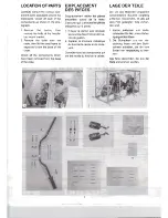
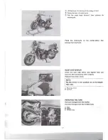
Страница 2: ...ssurer quil y a toutes les pieces indiquees sur la photo 1 Enlever Ie carton puis devisser les boulons fixant I etrier de fixa tion du guidon 2 Separer la structure metallique du fond de la caisse en la soule vant Controler taus les composants qui ant ete retires du fond de a caisse LAGE DER TEILE Die um das Motorrad verpackten verschiedenen Bauteile sorgfaltig entfernen UberprOfen ob aile auf dem...
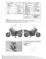
Страница 3: ... F Rear view mirror Warning label set Warning label set Battery electrolyte container 2 7 4 1 Right and Left For CC selection For CD selection Clip 1 For throttle cable G Owner s manual 1 T L I 0010 U 00 Outside diameter mm 10 Inside diameter mm L Length mm T Thickness mm NOTE The parts shown as Item D and E in the above table are supplied for limited markets Parts listed above are installed respe...
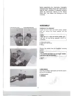
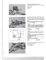
Страница 4: ...ch master cylinder bolts and remove the master cylinder from the bracket NOTE Keep the front brake and clutch master cylin der with Its cap facing upwards until it is installed A Clutch master cylinder B Front brake master cylinder C Bolt 0 Bracket Remove the bracket from the handlebar mounting position NOTE The bracket and bolts 8 re no longer needed and these may be discarded A Bracket B Bolt HA...
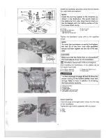
Страница 5: ...ghten the bolt of the rear side CAUTION Make sure that the clamp has no clearance at the front side as shown in the illustration Handlebar clamp bolt 23 N m 2 3 kgf m After installing the handlebars fit the plastic cap on the head of each bolt A 8 x 40 mm allen bolt C Plastic cap 00 11 0 mm B 8 x 40 mm allen bolt D Punch mark The line drawings on page 44 and 45 show the proper routing of the contr...
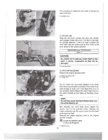
Страница 6: ...ing bolt 10 N m 1 0 kgf m NOTE To install the holder correctly first tighten the bolt of the upper side with speci1ied torque and then tighten the bolt of the lower side A Holder D Flange boll 8 Master cylinder E Dot mark C Flange bolt NOTE Install the holder according 10 the mark UP NOTE Make sure that the ho ider has no clearance at the upper side as shown CAUTIOfi I Check for brake fluid leakag...
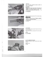
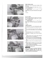
Страница 7: ...en the throttle assembly with the two allen bolts Check to ensure that the throttle operates freely and closes automatically A Throttle assembly B Allen bolt LEFT SWITCH Insert the boss of the left switch holder into the hole on the handlebars Tighten the left switch assembly with the two screws A Boss B Hole C 5 x 44 mm screw D 5 x 25 mm screw CLUTCH MASTER CYLINDER Remove the bolts and holder fr...
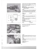
Страница 8: ...D Flange bolt B Master cylinder E Dol mark C Flange bolt NOTE Install the holder according to the mark UP NOTE Make sure that the holder has no clearance at the upper side as shown ICAUTION I I Check for clutch fluid leakage A Boll C Master cylinder B Holder D Handlebars Connect the clutch lever position switch lead wires to the clutch lever position switch A Clutch lever position switch B Lead wI...
Страница 9: ... I The end of the clip face to the left side A Clip B Throttle cable returning cable C Throttle cable pulling cable HANDLEBAR BALANCER Assemble the handlebar balancer parts as shown A Baiancer weight B 6 x 120 mm screw C Flange rubber cushion l 35 0 mm 0 Spacer L 50 0 mm E WasherOD 16 0 mm 10 6 5 mm F Rubber cushion L 15 0 mm G 6 mm flange nul With the screw not tightened insert the balancer sub a...
Страница 10: ...d the remove the hoist hook REAR VIEW MIRROR Instal the rear view mirror and tighten lock nut securely after positioning them properly Replace the rubber boots NOTE Fix the mirror In the position so as to secure rear view A Rear view mirror B Lock nut REMOVING THE TAPE Remove the tape from the muffler Remove the tape from the throttle body A Tape B Muffler C Throttle body 17 ...
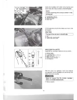
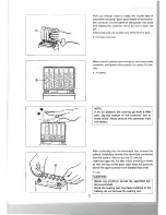
Страница 11: ... from the motorcycle A Document tray Filling electrolyte Remove the aluminium tape sealing the battery elec trolyte filler holes A Aluminium ape B Electrolyte filler hare Remove the caps from the electrolyte container NOTE Use the removed caps as the sealed caps of battery tiller holes Do not remove or pierce the sealed areas of the electrolyte container A Caps B Sealed area 21 ...
Страница 12: ...les NOTE If no air bubbles are coming up from a filler port tap the bottom of the container two or three times Never remove the container from the battery After confirming that the electrolyte has entered the battery completely remove the electrolyte containers from the battery Wait for around 20 minutes Insert the caps into the filler holes pressing in firmly so that the top of the each caps does...
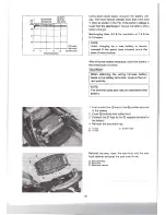
Страница 13: ...s have elapsed since the date of manufacture After filling the battery electrolyte install the battery in the motorcycle as follows ICAUTIONI When attaching the wiring harness battery leads to the battery terminals observe the cor rect polarity NOTE The terminal bolts and nuts are attached to the battery 1 First connect the lead to the l positive terminal of the battery 2 Cover terminal with rubbe...
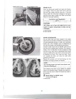
Страница 14: ...y there is air in the hydraulic circuit To bleed the air from the front brake use the following procedure Connect a clear hose to the air bleeder valve and run the hose into a suitable clear container Pour approxi mately 1 2 in of brake fluid into the container so that the end of the clear hose is submerged and cannot draw any additional air back into the circuit during the air bleeding servicing ...
Страница 15: ...emove the engine sprocket cover A Engine sprocket cover B Flange bolt Any air which may have been trapped in the clutch fluid circuit must be bled completely If the clutch lever feels spongy or weak then most likely there is air in the hydraulic circuit Bleed the clutch fluid circuit in the same manner as the brake air bleeding proce dure NOTE Do not drop clutch fluid level below II ower level lin...
Страница 16: ...ble play should be 2 0 4 0 mm 0 08 0 16 in at the throttle grip Throttle cable play 2 0 4 0 mm 0 08 0 16 in If adjustment is necessary carry out the procedure below 1 Loosen the lock nut of the throttle returning cable and fUlly turn in the adjuster 2 Loosen the lock nut of the throttle pUlling cable 3 Turn the adjuster in or out until the throttle cable play is 2 0 4 0 mm 0 08 0 16 in at the thro...
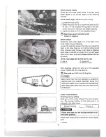
Страница 17: ... when there is 20 30 mm 0 8 1 2 in up and down slack in the chain at a point midway between the two sprockets Drive chain slack 20 30 mm 0 8 1 2 in A Axle nut C Adjuster bolt 8 Lock nut 0 Reference marks After adjusting tighten the axle nut to the specified torque Tighten the lock nuts securely t Rear axle nut 100 N m 10 0 kgf m ICAUTIONI Make sure that the rear sprocket is properly aligned with t...
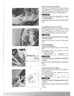
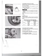
Страница 18: ...on Be sure to adjust the damping force on both front forks equally Please refer to the owner s manual for correct adjust ment REAR SUSPENSION Checking spring setting Make sure of the spring setting of the rear suspen sion The standard setting of this motorcycle is as indi cated in the table below I L _ Standard setting P_O_s_iti_o_n_1_Y _2 8BImmJ Check that right and left settIngs are the same pos...
Страница 19: ... Using an accurate air gauge check the air pressure of the front and rear tires The pressure should be as shown COLO INFLATION TIRE PRESSURE SOLO RIDING DUAL RIDING 250 kPa 250 kPa FRONT 2 50 kg em 2 50 kg em2 36 psi 36 psi 250 kPa 290 kPa REAR 2 50 kg em 2 90 kg cm2 36 psi 42 psi HEADLIGHT BEAM ADJUSTMENT The headlight beam can be adjusted both horizontally and vertically if necessary To adjust t...
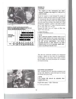
Страница 20: ... F Jevel If the level is above the F mark drain oil to F level Replace the drain plug and engine oil filler plug Tighten them securely A Engine oil filler plug B Engine oil level inspection window NOTE Use a premium quality 4 stroke motor oil to ensure longer service life of your motorcycle Use only oils which are rated SF or SG under the API service classification The recom mended viscosity is SA...
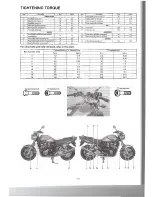
Страница 21: ...bolt 23 2 3 P I Rear axle nut 100 10 0 f BRAKE ABSORBER G Front brake and clutch masler cylinder Q I ReaJ shock absorber nUl Upper 23 I 2 3 mounting bolt 10 1 0 I I R Rear shock absorber nul Lower 35 3 5 H Front brake caliper mounting boll 26 2 6 OTHERS I Rear brake master cylinder mounting boll 10 1 0 S Rear S ovingarm pivot nut I 120 I 12 0 J Rear brake caliper mounting b olt 26 2 6 Bolt Diamete...
Страница 22: ...use More than 2 mm 0 08 in 2 mm ou plus Mehr als 2 mm Squeeze the brake lever fUlly and check or adjust the clearance between the lever and throttle case to provide more than 2 mm 0 08 in Serrer afond Ie levier de frein et contr61er ou regler Ie jeu entre Ie levier et Ie boitier de commande des gaz afin qu i salt plus de 2 mm Den Bremshebel ganz ziehen und das Spiel zwischen Bremshebel und Gasgeha...
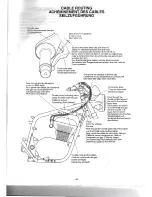
Страница 23: ...einwertergehiiuse Clamp I hl __Collier de serrage Klemme Clamp Collier de sen age Klemme Frame Cadre Rahmen Wiring harness 1 Faisceau de cables Kabelbaum Rear fender Garde boue arriere Hinterradschulzblech Air cleaner Fillre aair Luftfilter Regulator rectifier Regulateur redresseur Regler Gleichrichter Clamp Collier de serrage Klemme Regulator rectifier Regulaleur redresseur Regler Gleichrichler C...
Страница 24: ...e and ctrclip Fasteners Check Pain and chrome InspectlWash and polish Warning label For E 19 market Select Stick Appropriate language Cold Tire Inflation Pressure SOLO RIDING DUAL RIDING 250 kPa 250 kPa FRONT 2 50 kg cm2 2 50 kg cm2 36 psi 36 psi 250 kPa 290 kPa REAR 2 50 kg cm2 2 90 kg cm2 36 psi 42 psi IElECTRICALS ITEM CHECK FOR Light Llghting Adjust Tail Brake light Headlight high low beam Tur...