background image


SUSPA GmbH 


Installation Instructions 


English 


SUSPA Movotec SMS 


Read installation instructions carefully before initial use! 
Follow the safety instructions! 
This partly completed machinery is intended to be incorporated into oth-
er  machinery,  other  partly  completed  machinery/equipment  or  to  be 
joined  with  another  framework  so  as  to  form  a  complete  machine  as 
specified under the Machinery Directive. A conformity assessment proce-
dure must be carried out on the whole completed machine in accordance 
with the Machinery Directive before it can be put into operation. 
 
No revision service applies to this documentation. The current installation 
instructions are available at  
https://www.suspa.com/uk/downloads/ 
 
February 2018 

Содержание Movotec SMS

Страница 1: ...eted machinery equipment or to be joined with another framework so as to form a complete machine as specified under the Machinery Directive A conformity assessment proce dure must be carried out on th...

Страница 2: ...ocuments have been read and under stood These installation instructions must be kept in a well known and easily accessible lo cation and read in case of any doubt The manufacturer is not liable for in...

Страница 3: ...15 3 3 Safety Equipment 15 3 4 Additional Instructions 15 4 Design and Function 16 4 1 Technical Specifications 16 4 2 Design and Function of the Height Adjustment System 17 5 Transport 18 5 1 Safety...

Страница 4: ...d Operational Messages 39 7 6 1 1 Manual Switch Error Messages 39 7 6 1 2 Important Display Codes and their Meanings 39 7 6 2 Troubleshooting 40 7 6 2 1 Malfunctions in the Cycle Procedure 42 8 Servic...

Страница 5: ...ignal Words and Signal Colors The following signal words are based on DIN EN 82079 1 and ANSI Z 535 4 and are used in this documentation The safety colors have been adopted from the standard ISO 3864...

Страница 6: ...nstallation instructions and require particular attention depending on the signal word and symbol combination Symbol Use Explanation Note Important information for under standing the device or for opt...

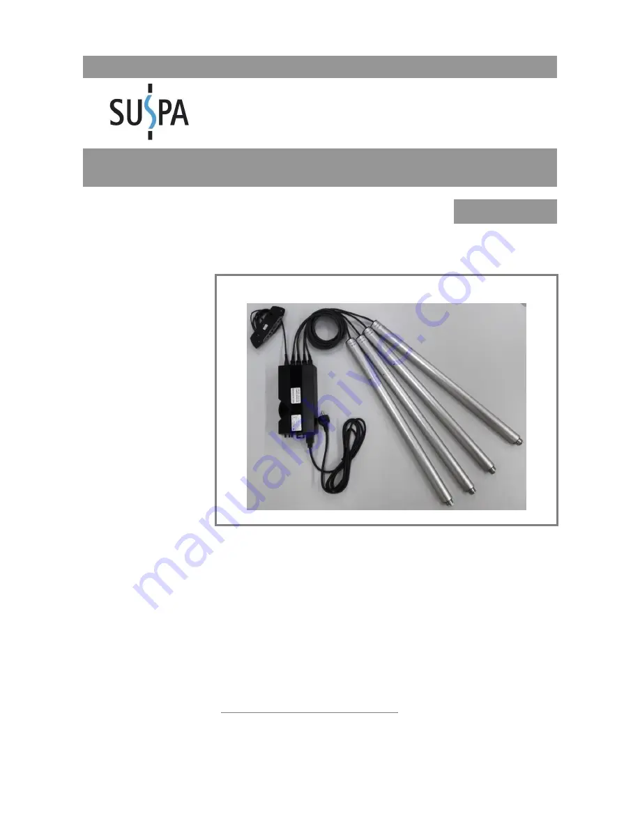
Страница 7: ...nd Notes 2 1 Designation SUSPA Movotec SMS Consisting of Sheet 004 1006 ZB Actuator SMS Sheet 198 1002 SMS controller SCT 4 incl power cable 098 10087 manual switch UBM F 2 P or 098 10088 manual switc...

Страница 8: ...o be usage not in the manner intended and thus improper In this case the safety and protective functions of the Height Adjust ment System may be impaired This partly completed machinery is intended to...

Страница 9: ...out prior consultation with the company SUSPA GmbH Operating the Height Adjustment System contrary to the specifications provided in the operat ing instructions regarding safety instructions installat...

Страница 10: ...ividual components Inadequate implementation of the prescribed maintenance operations Disasters caused by external influence or force majeure Repairs that have not been carried out by the manufacturer...

Страница 11: ...as well as all additional documents of the assemblies provided by external suppliers must be Observed read and understood by all persons working on the Height Adjustment System this applies in partic...

Страница 12: ...is X X X X X Troubleshooting by Error Code X X X X X Repair X X Decommissioning Dismantling X X X X Table 4 Target group Operating personnel A person who has been instructed and if required trained by...

Страница 13: ...nically or electrically induced hazards Mainte nance personnel must meet the following requirements Technical training Knowledge and experience Knowledge of applicable standards Ability to assess assi...

Страница 14: ...user third parties or to the component use the component only for intended purpose and in perfect operating condition in terms of safety The operator of the component or the persons assigned by the sa...

Страница 15: ...lifting elements the controller or on the manual switch Take the residual risk into consideration with the construction and while preparing the oper ating instructions of the final product 3 3 Safety...

Страница 16: ...ndard 0 4 W Optional Protection class II Protective insulation Performance data Traversing velocity ca 8 mm s ca 16 mm s Max lifting capacity and holding load per lifting element 150 kg 75 kg Max lift...

Страница 17: ...justment System possible Figure 1 Electrical controller SMS SCT4 Figure 2 Electrical lifting element Figure 3 Simple manual switch UBM F 2 p Figure 4 Programmable manual switch UBS 6 LCD optional The...

Страница 18: ...over which loads are moved Re move obstacles and stumbling points CAUTION Damage caused by improper transport Transport with extended lifting elements may result in risk of damage to property or pers...

Страница 19: ...uspend the operation of the product if you notice that the motor cable or power cord are dam aged and replace the damaged components without delay Never attempt to repair damaged mo tor cables or powe...

Страница 20: ...rical controller 1 x Manual switch 1 x Cold device plug cable 4 x Leveling Feet Optional 4 x Fastening elements Set Optional For an 8 leg system 8 x Electrical lifting elements 8 x Drilling template 2...

Страница 21: ...ust be ensured IMPORTANT Observe the country specific regulations regarding setup and operation of workplaces with respect to lighting of the workstations For example Lighting in accordance with ASR A...

Страница 22: ...ing the holes to be drilled and facilitating the in stallation Keep electrical cord away from sharp edges and moving parts Avoid contact with moisture and heat Attach the electrical wires and power co...

Страница 23: ...ensure that the drill templates for the lifting elements adhere to them Align the workplace as described in the following in order to facilitate the positioning and in stallation of the components Fig...

Страница 24: ...lements depends on the model number of the lifting elements The model number of the lifting element is located on the product label The installation instructions for the lifting elements is located on...

Страница 25: ...hat they are fastened securely to the workplace Note that you do not over tighten the lifting element mounting screws recommended tightening torque 4 0 4 5 Nm Make sure that the electrical lines of ea...

Страница 26: ...Installation SUSPA Movotec SMS Installation Instructions Page 26 Figure 10 Dimensions of the lifting element...

Страница 27: ...lar devices Make sure that connecting cables do not have kinks or are not exposed to mechanical stress For protection against over voltage that may occur during thunderstorms it is recommended that yo...

Страница 28: ...Installation SUSPA Movotec SMS Installation Instructions Page 28 Figure 11 Attaching the electrical controller screw linkages left 3x right 1x Figure 12 Electrical controller dimensions connections...

Страница 29: ...nsure sufficient cable length for the electrical controller when positioning the manual switch Mount the manual switch with two screws to the workplace When attaching insert metal washers between the...

Страница 30: ...Installation SUSPA Movotec SMS Installation Instructions Page 30 Figure 15 Attaching of the programmable manual switch UBS 6 LCD Figure 16 Dimensions of the programmable manual switch UBS 6 LCD...

Страница 31: ...upply variant The correct variant of the controller can be supplied only if you specify the supply variant at the time of placing the order If more than four lifting elements are used in a height adju...

Страница 32: ...her way Fasten the cables with adequate strain relief and adequate protection against kinks Wind the excess length of cables together in rolls with a diameter of approx 150 mm and fas ten them with th...

Страница 33: ...the entire work surface is horizontal and level Create a good starting point for leveling by completely threading the leveling feet in the lift ing elements The screw insertion depth is up to 32 mm I...

Страница 34: ...lts and locknut SW17 2 Steel insert with SW23 lifting element Fix the locknuts tightly to all leveling feet to ensure that the workplace remains leveled during operation CAUTION Make sure to hold the...

Страница 35: ...7 6 1 7 2 Tests Prior to Switching the Machine On Check all electrical and mechanical connections Check whether there are damages to electrical wires which may have occurred during un packing or inst...

Страница 36: ...ystem CAUTION Danger posed by thermal energies The motor housing may become hot if the operating time exceeds the duty cycle The duty cycle must not be exceeded in order not to damage the system Excee...

Страница 37: ...ch UBM F 2 p 7 4 1 2 Programmable Manual Switch UBS 6 LCD Optional Symbol Function Up Press the Up button until the workplace has reached the desired height or the maximum height Down Press the Down b...

Страница 38: ...speed until the lower mechanical end stop on the lifting el ements is reached The controller acknowledges this reset drive with a signal tone The workplace can now be moved with the two direction butt...

Страница 39: ...s of the lifting elements is too large Table 10 Error and status codes 7 6 1 2 Important Display Codes and their Meanings Compulsory reset The Height Adjustment System is not properly initialized duri...

Страница 40: ...on Then perform reset Connection error Manual switches motors or power plugs are not correctly connected to the controller Indicator Diverse symptoms Solution Check the correct connection of the compo...

Страница 41: ...t whether the socket is supplying power or is switched on Replace the manual switch in order to en sure that the manual switch is not defective If the error persists continue with step 2 2 The control...

Страница 42: ...42 7 6 2 1 Malfunctions in the Cycle Procedure Operation is interrupted The type of malfunction is displayed on the manual switch The fault must be rectified Please contact the professional personnel...

Страница 43: ...ady for small parts that may have to be disassembled Only use original spare parts approved by the manufacturer Tighten screw connections that have been loosened after doing maintenance and service wo...

Страница 44: ...ponents with a mild detergent and a damp cloth Liquid entry of any kind must be strictly avoided Do not use any corrosive detergents or high pressure washing systems to clean the compo nents of the He...

Страница 45: ...ith the ground IMPORTANT One indicator of a uniform load distribution is that all the lifting elements in the area of drive units motor cable outlet have the same temperature 8 3 2 Contamination No st...

Страница 46: ...t Adjustment System parts in such a way that they are protected from damag es by external influences during storage If necessary use cardboard boxes and other packaging material Secure the Height Adju...

Страница 47: ...ive 2002 95 EC internationally RoHS with effect from 7 1 2006 or the respective national legislation The disposal of the components also operating materials in other countries should be performed in a...

Страница 48: ...rning 6 Table 4 Target group 12 Table 5 Technical Specifications 16 Table 6 Operating conditions 20 Table 7 Lighting requirements 21 Table 8 Function of the simple manual switch UBM F 2 p 37 Table 9 F...

Страница 49: ...hing the electrical controller screw linkages left 3x right 1x 28 Figure 12 Electrical controller dimensions connections 28 Figure 13 Attaching the simple manual switch UBM F 2 p 29 Figure 14 Dimensio...

Страница 50: ...2011 Safety of machinery Risk assessment and risk reduction 2 DIN EN ISO 13849 1 2008 Safety of Machinery Safety related components of control systems Part 1 General design guidelines 3 DIN EN 60335...

Отзывы: