


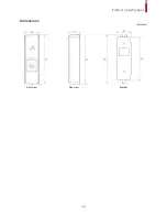


Installation
12
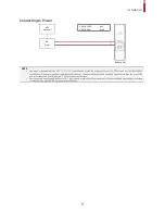
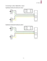
Connecting to a Relay
Fail Safe Lock
To use fail safe lock, connect N/C terminal as shown below. Normally, there is a current flowing through the relay and the door is
opened when the relay is activated by blocking current flows. The door is opened when there is a blackout or power failure
caused by external conditions.
NOTE
•
Install the diode at both ends of the wire for the door lock device as shown in the figure to protect the relay from being damaged by
the reverse current induced when the door lock device operates.
•
Make sure that the direction of the installed diode is correct.
•
Install the diode close to the door lock device.
•
Use a separate power source for BioEntry Plus from the door lock device.
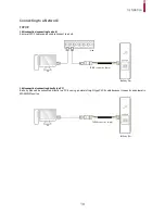
Fail Secure Lock
To use fail secure lock, connect N/O terminal as shown below. Normally, there is no current flowing through the relay and the
door is opened when the relay is activated by a current flows. The door is locked when there is a blackout or power failure
caused by external conditions.
NOTE
•
Install the diode at both ends of the wire for the door lock device as shown in the figure to protect the relay from being damaged by
the reverse current induced when the door lock device operates.
•
Make sure that the direction of the installed diode is correct.
•
Install the diode close to the door lock device.
•
Use a separate power source for BioEntry Plus from the door lock device.
BioEntry Plus
7 - RLY NO
White
6 - RLY COM
Blue
6
7
Deadbolt /
Door strike
DC
Power
BioEntry Plus
Deadbolt /
Door strike
DC
Power
6 - RLY COM
Blue
5 - RLY NC
Orange
6
5


