


WINCH INSTALLATION
WINCH INSTALLATION
1. The hydraulic motor should be bolted into position using the m12 bolts and washers supplied.
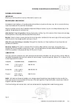
2. Refer to the mounting diagram (Fig. 3). All dimensions are in mm.
3. Winch mounting can be via a winch mount plate (Part No. 7840, not 8569).
4. The winch (together with it’s mounting plate if fitted) must be securely bolted on to a mounting surface that is flat to within 0.5mm and
sufficiently stiff to prevent flexing. A minimum of 6.4mm (0.25”) thick steel plate should be used. Remember that the winch is only as strong
as it’s mounting.
5. All four mounting holes marks ‘A’ must be used.
6. Use the spacers provided.
7. Althought the winch may be mounted in either the ‘overwound’ or ‘underwound’ positions, ‘underwound’ is recommended.
8. Mounting bolts must be 8.8 grade High Tensile Steel.
04
WINCH INSTALLATION
04-1
A
C
D
C
WINCH
DIMENSION A
DIMENSION C
DIMENSION D
8569
349mm [13.8”]
197mm [7.8”]
210mm [8.3”]
8588
414mm [16.3”]
262mm [10.3”]
275mm [10.8”]
8589
414mm [16.3”]
262mm [10.3”]
275mm [10.8”]
OVERWOUND POSITION (NOT RECOMMENDED)
Fig. 3


