background image

1-5

Chapter 1: Introduction

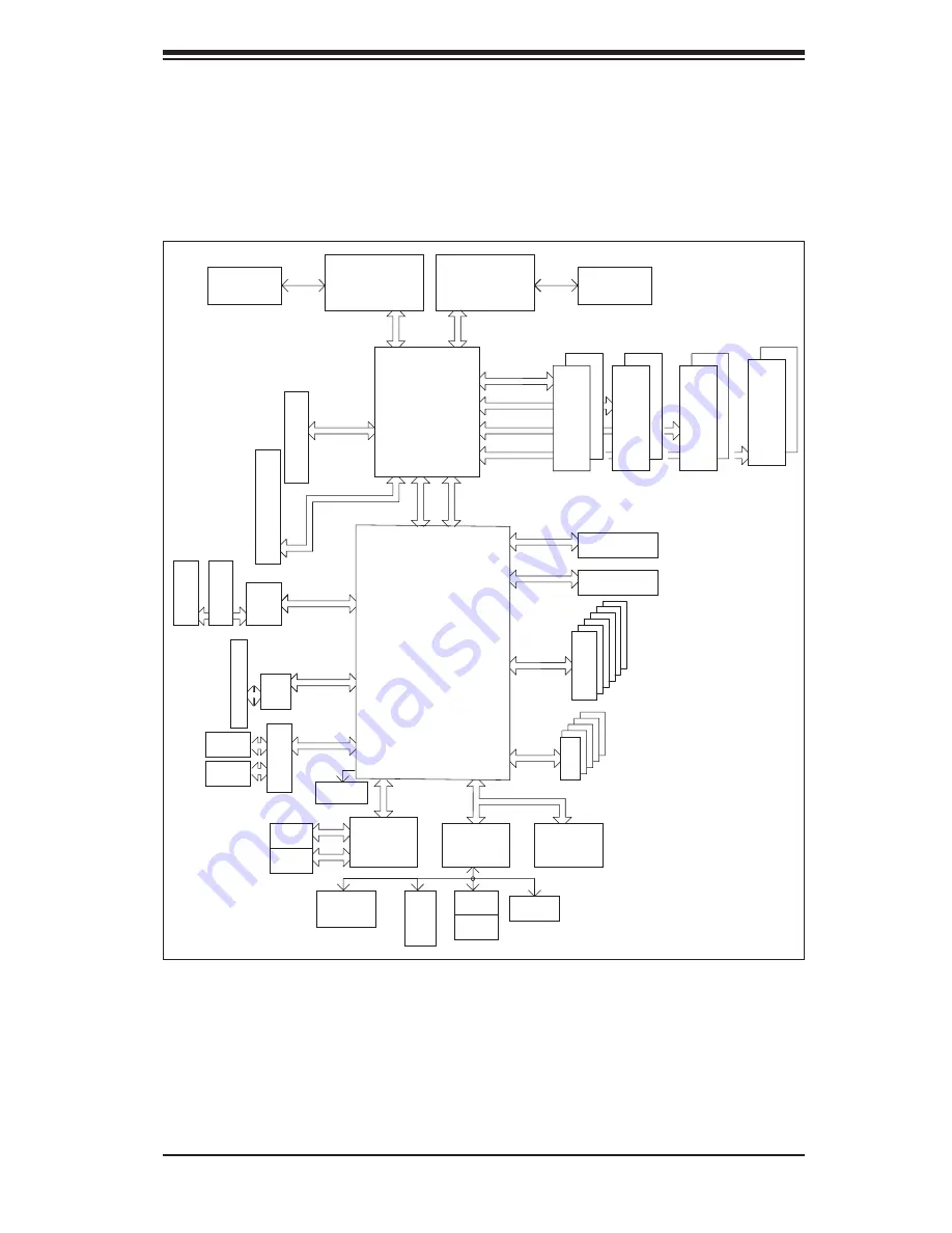
Figure 1-1.  Intel 5000X Chipset: 

System Block Diagram


Note: This is a general block diagram.  Please see Chapter 5 for details.

   MCH

5000X

PROCESSOR#2

ESB2

PCI-E_X16_Slot

FBD CHNL0

FBD CHNL1

FBD CHNL2

FBD CHNL3

FBD DIMM

#1B

#2B

#3B

#4B

#1A

#2A

#3A

#4A

FBD DIMM

FBD DIMM

FBD DIMM

PCI-ExpX16

PCI33 MHz

PCI-EXP X8

PXH-V

PCI-X 133

PCI-X Slot

PCI-Exp X4

PCI-E_X4_in_X16_Slot

SATA

#0

#1

#2

#3

#4

#5

PCIE X4

PCIE X4

GILGAL

GB LAN

FWH

RJ45

RJ45

LPC

COM1

SIO

W83627

FDD

USB

#0

#1

#2

#3

#4

1U-IPMI

CONN

System 
PWR

EBUS CONN

EXP. BUS

IDE CONN

ATA 100

KB

MS

KUMERAN

USB 2.0

3.0 Gb/S

VRM

ISL6307

VRM

ISL6307

PROCESSOR#1

MT/S

667/1067/1333

MT/S

PARALLEL

PORT

J13

#2

J9

#4

J5

#6

HG

PCI-X Slot ZCR

SCSI

7902

J12

#1

PCI-X Slot

J14

#3

PCI32_Slot

J6

#5

Greencreek

667/1067/1333

HD Audio

Note: 

the X7DAE does not include the SCSI controller and ports.  

Содержание SuperWorkstation 7045A-8

Страница 1: ...SUPERWORKSTATION 7045A T SUPERWORKSTATION 7045A 8 USER S MANUAL 1 0a SUPER...

Страница 2: ...the right to make changes to the product described in this manual at any time and without notice This product including software if any and documenta tion may not in whole or in part be copied photoc...

Страница 3: ...M Manual Organization Chapter 1 Introduction The rst chapter provides a checklist of the main components included with the server system and describes the main features of the SUPER X7DAE X7DA8 server...

Страница 4: ...his chapter when adding or removing processors or main memory and when recon guring the serverboard Chapter 6 Advanced Chassis Setup Refer to Chapter 6 for detailed information on the SC743TQ 645 SC74...

Страница 5: ...v Preface Notes...

Страница 6: ...he System into a Rack 2 4 2 5 Checking the Serverboard Setup 2 8 2 6 Checking the Drive Bay Setup 2 9 Chapter 3 System Interface 3 1 Overview 3 1 3 2 Control Panel Buttons 3 1 Power 3 1 Reset 3 1 3 3...

Страница 7: ...itions 5 12 ATX Power Connector 5 12 Secondary Power Connector 5 12 Processor Power Connector 5 12 NMI Button 5 12 Power LED 5 12 HDD LED 5 13 NIC LEDs 5 13 Overheat Fan Fail LED OH 5 13 Power Fail LE...

Страница 8: ...N2 LEDs 5 23 SCSI Activity LED Indicators 5 23 Onboard Power LED 5 23 5 11 Parallel Port Floppy and Hard Drive Connections 5 24 Parallel Port Connector 5 24 Floppy Connector 5 25 SATA Ports 5 25 IDE C...

Страница 9: ...Setup 7 2 7 3 Main BIOS Setup 7 2 7 4 Advanced Setup 7 7 7 5 Security Settings 7 22 7 6 Boot Settings 7 23 7 7 Exit 7 24 Appendices Appendix A BIOS POST Messages A 1 Appendix B BIOS POST Codes B 1 App...

Страница 10: ...Notes x SUPERWORKSTATION 7045A T 7045A 8 User s Manual...

Страница 11: ...ents have been included with the SuperWorkstation as listed below One 1 3 5 oppy drive FPD PNSC 02 1 Four 4 hot swap 80 mm chassis PWM fans FAN 0074 One 1 90 mm PWM exhaust fan FAN 0091 One 1 air shro...

Страница 12: ...an inter leaved con guration which requires modules of the same size and speed to be installed in pairs Serial ATA 7045A T An on chip ESB2 SATA controller is integrated into the X7DAE to provide a si...

Страница 13: ...Features Other onboard features that promote system health include onboard voltage moni tors a chassis intrusion header auto switching voltage regulators chassis and CPU overheat sensors virus protect...

Страница 14: ...re A main power button and a system reset button are also included Note the power supply fail LED is intended for use with redundant power supply systems and so is not needed for the 7045A T 7045A 8 I...

Страница 15: ...PCI EXP X8 PXH V PCI X 133 PCI X Slot PCI Exp X4 PCI E_X4_in_X16_Slot SATA 0 1 2 3 4 5 PCIE X4 PCIE X4 GILGAL GB LAN FWH RJ45 RJ45 LPC COM1 SIO W83627 FDD USB 0 1 2 3 4 1U IPMI CONN System PWR EBUS CO...

Страница 16: ...om Europe Address SuperMicro Computer B V Het Sterrenbeeld 28 5215 ML s Hertogenbosch The Netherlands Tel 31 0 73 6400390 Fax 31 0 73 6416525 Email sales supermicro nl General Information support supe...

Страница 17: ...skip ahead to Section 2 5 2 2 Unpacking the System You should inspect the box the system was shipped in and note if it was damaged in any way If the server itself shows damage you should le a damage...

Страница 18: ...s should be attached to the rack In multiple rack installations the racks should be coupled together Always make sure the rack is stable before extending a component from the rack You should extend on...

Страница 19: ...mised Mechanical Loading Equipment should be mounted into a rack so that a hazardous condition does not arise due to uneven mechanical loading Circuit Overloading Consideration should be given to the...

Страница 20: ...s that came with the rack unit you are using Identifying the Sections of the Rack Rails The optional rackmount kit CSE PT26 or CSE PT26B black includes two rack rail assemblies Each of these assemblie...

Страница 21: ...r chassis rail sections you just removed along the side of the chassis making sure the screw holes line up Note that these two rails are left right speci c Screw the rail securely to the side of the c...

Страница 22: ...Position the xed rack rail sliding rail guide assemblies at the desired location in the rack keeping the sliding rail guide facing the inside of the rack Screw the assembly securely to the rack using...

Страница 23: ...hese rst keeping in mind that they are left right speci c marked with L and R Then line up the rear of the chassis rails with the front of the rack rails Slide the chassis rails into the rack rails ke...

Страница 24: ...ver You can then lift the cover from the chassis to gain full access to the inside of the server 2 Check the CPUs processors You may have one or two processors already installed into the serverboard E...

Страница 25: ...ll a oppy disk drive to the system 4 Check the SATA SCSI disk drives Depending upon your system s con guration your system may have one or more drives already installed If you need to install SATA SCS...

Страница 26: ...2 10 SUPERWORKSTATION 7045A T 7045A 8 User s Manual Figure 2 5 Accessing the Inside of the System Rack Con guration shown...

Страница 27: ...of speci c components There are also two buttons on the chassis control panel 3 2 Control Panel Buttons There are two push buttons located on the front of the chassis These are in order from left to r...

Страница 28: ...nel activity On the 7045A T 7045A 8 this LED indicates SATA SCSI IDE drive activity when ashing NIC Indicates network activity on LAN1 when ashing NIC Indicates network activity on LAN2 when ashing Ov...

Страница 29: ...er LEDs Each SATA SCSI drive carrier has two LEDs Green When illuminated the green LED on the front of the SATA SCSI drive carrier indicates drive activity A connection to the SATA SCSI SCA backplane...

Страница 30: ...3 4 SUPERWORKSTATION 7045A T 7045A 8 User s Manual Notes...

Страница 31: ...ard memory modules and the oppy drives not necessary for SATA SCSI drives When disconnecting power you should first power down the system with the operating system and then unplug the power cord from...

Страница 32: ...r be pulled into a cooling fan The power supply power cord must include a grounding plug and must be plugged into grounded electrical outlets Serverboard Battery CAUTION There is a danger of explosion...

Страница 33: ...efore removing the board from the antistatic bag Do not let components or PCBs come into contact with your clothing which may retain a charge even if you are wearing a wrist strap Handle a board by it...

Страница 34: ...o ensure proper cooling Out of warranty damage to the 7045A T 7045A 8 system can occur if this practice is not strictly followed Figure 4 1 Installing the Onboard Battery LITHIUM BATTERY BATTERY HOLDE...

Страница 35: ...hat the size and weight of the serverboard can cause it to bend if handled improperly which may result in damage To prevent the serverboard from bending keep one hand under the center of the board to...

Страница 36: ...LGA 771 CPU or when receiving a serverboard with an LGA 771 CPU pre installed make sure that the CPU plastic cap is in place and none of the CPU pins are bent otherwise contact the retailer immediate...

Страница 37: ...or vertically and do not rub the CPU against any surface or any of the contacts which may damage the CPU and or contacts 7 With the CPU in the socket inspect the four corners of the CPU to make sure...

Страница 38: ...m 3 Screw in two diagonal screws i e the 1 and the 2 screws until just snug Do not fully tighten the screws or you may damage the CPU 4 Add the two remaining screws then nish the installation by fully...

Страница 39: ...ocations If you are con guring the system keep the air ow in mind when routing the cables The following data cables with their serverboard connector locations noted should be connected See the serverb...

Страница 40: ...posite sides of each header All JF1 wires have been bundled into single keyed ribbon cable to simplify their connection The red wire in the ribbon cable plugs into pin 1 of JF1 Connect the other end o...

Страница 41: ...O ports are color coded in conformance with the PC 99 speci cation See Figure 5 4 below for the colors and locations of the various I O ports Figure 5 4 Rear Panel I O Ports Mouse Keyboard USB0 1 2 3...

Страница 42: ...t a time beginning with Bank 1 then Bank 2 and so on Insert each DIMM module vertically into its slot Pay attention to the notch along the bottom of the module to prevent inserting the DIMM module inc...

Страница 43: ...s one 64 bit 100 MHz ZCR slot and one 32 bit 33MHz PCI slot 2 PCI card installation Before installing a PCI add on card make sure you install it into a slot that supports the speed of the card see ste...

Страница 44: ...M 3A DIMM 2B DIMM 2A DIMM 1B DIMM 1A North Bridge LP IPMI Slot 6 x16 PCI Express Slot 5 33 MHz PCI Slot 4 x4 PCI Express Slot 3 133 MHz PCI X Slot 2 133 MHz PCI X Slot 1 100 MHz PCI X ZCR COM2 PXH BIO...

Страница 45: ...Headers COM1 COM2 COM1 COM2 Serial Port Connector Header FAN 1 8 Fan Headers 1 8 IDE 1 IDE 2 IDE Hard Drive Compact Flash Card Connectors J17 System Management I2 C Power Header J18 System Management...

Страница 46: ...Secondary 12v 8 pin connector JPW2 must also be connected to your power supply See the table on the right for pin de nitions NMI Button Pin De nitions JF1 Pin De nition 19 Control 20 Ground Processor...

Страница 47: ...the right for pin de nitions NIC2 LED The NIC2 Network Interface Control ler LED connection is located on pins 9 and 10 of JF1 Attach the NIC2 LED cable to display network activity Refer to the table...

Страница 48: ...itions Universal Serial Bus Ports Four Universal Serial Bus ports are located beside the PS 2 keyboard mouse ports USB0 is the bottom connector and USB3 is the top con nector See the table on the righ...

Страница 49: ...serverboard layout for location See the table on the right for pin de nitions Note Pin 10 is included on the header but not on the port NC indicates no connection Serial Port Pin De nitions COM1 COM2...

Страница 50: ...NC Speaker Connector Pin De nitions JD1 Pin Function De nition 4 Speaker data red wire 5 Key No connection 6 Key 7 Speaker data Extra Universal Serial Bus Headers Two additional USB headers are locat...

Страница 51: ...use this feature SMB The System Management Bus header for the PCI bus designated J18 is located near the SATA ports Connect the appropriate cable here to utilize SMB on your system See the table on t...

Страница 52: ...for sound output when AC 97 is enabled see diagram at right To activate onboard audio please enable the JPAC jumper Blue Rear L R speakers Line In Green Front L R speakers Line Out Pink Center subwoof...

Страница 53: ...CMOS and will also clear any passwords Instead of pins this jumper consists of contact pads to prevent accidentally clearing the contents of CMOS To clear CMOS 1 First power down the system and unplu...

Страница 54: ...be enabled in BIOS Note When enabled the user needs to write their own application software to disable the Watch Dog Timer JLAN Enable Disable Jumper Settings JPL1 JPL2 Jumper Setting De nition Pins...

Страница 55: ...enable termination See the table on the right for jumper settings Note In order for the SCSI drives to function properly please do not change the default setting enabled set by the manufacturer SCSI T...

Страница 56: ...I2 C3 and JI2 C4 allow you to connect speci c PCI X PCI Express slots to the System Management I2 C Bus The default setting for all jumpers is pins 2 3 to disable the connection These jumpers must be...

Страница 57: ...ion speed LED JLAN LED Connection Speed Indicator LED Color De nition Off No connection or 10 MHz Green 100 MHz Amber 1 GHz SCSI Activity LED Indicators X7DA8 only There are two SCSI activity LED indi...

Страница 58: ...ppy disk drives The connector with twisted wires always connects to drive A and the connector that does not have twisted wires always connects to drive B Parallel Port Connector See the table below fo...

Страница 59: ...le 11 Ground 12 Drive Select B 13 Ground 14 Drive Select B 15 Ground 16 Motor Enable 17 Ground 18 DIR 19 Ground 20 STEP 21 Ground 22 Write Data 23 Ground 24 Write Gate 25 Ground 26 Track 00 27 Ground...

Страница 60: ...d 27 IOCHRDY 28 BALE 29 DACK3 30 Ground 31 IRQ14 32 IOCS16 33 Addr1 34 Ground 35 Addr0 36 Addr2 37 Chip Select 0 38 Chip Select 1 39 Activity 40 Ground IDE Connectors There are two IDE connectors IDE...

Страница 61: ...15 Ground 49 Ground 16 DIFFSENS 50 Ground 17 TERMPWR 51 TERMPWR 18 TERMPWR 52 TERMPWR 19 Reserved 53 Reserved 20 Ground 54 Ground 21 ATN 55 ATN 22 Ground 56 Ground 23 BSY 57 BSY 24 ACK 58 ACK 25 RST 5...

Страница 62: ...5 28 SUPERWORKSTATION 7045A T 7045A 8 User s Manual Notes...

Страница 63: ...s important to handle them very carefully The following measures are generally suf cient to protect your equipment from static discharge Precautions Use a grounded wrist strap designed to prevent stat...

Страница 64: ...RWORKSTATION 7045A T 7045A 8 User s Manual 6 x SATA Drive Bays 7045A T or 8 x SCSI Drive Bays 7045A 8 Figure 6 1 Chassis Front View System Reset Main Power System LEDs Floppy Drive 5 25 Drive Bays 2 U...

Страница 65: ...o the control panel side of the chassis The LEDs on the control panel inform you of system status see Figure 6 2 for details See Chapter 5 for details on JF1 Figure 6 2 Front Control Panel LEDs Power...

Страница 66: ...hot plug fan housing Depress the locking tab on a chassis cooling fan and pull the unit straight out by the handle see Figure 6 3 The fan wiring for these fans has been designed to detach automatical...

Страница 67: ...Chapter 6 Advanced Chassis Setup 6 5 Figure 6 4 Removing the Air Shroud Figure 6 3 Removing a Chassis Fan...

Страница 68: ...ow for the system For this reason even carriers without drives must remain in the server If you need to add a new SATA or SCSI drive insert the drive into the carrier with the printed circuit board si...

Страница 69: ...drives plug into a backplane that provides 3 GB s SATA Ultra320 dual channel operation for all installed drives A ribbon cable from JA1 on the serverboard should be connected to the IN connector on t...

Страница 70: ...6 7 SCSI Backplane Jumper Settings JP19 Buzzer Enable Closed On Enabled default Open Off Disabled LEDs Drive Fail LEDs Fail1 Fail2 Fail3 Fail4 Fail5 Fail6 Fail7 Fail8 Activity LEDs ACT1 ACT2 ACT3 ACT...

Страница 71: ...M into the bay and secure it to the chassis with the drive carrier screws you rst removed Attach the power and data cables to the drive Replace the top left chassis cover before restoring power to the...

Страница 72: ...fore removing and replacing the power supply unit for whatever reason Replacing the Power Supply 1 Accessing the power supply For safety reasons you will need to remove power from the system when repl...

Страница 73: ...f a backup battery pro vides power to the CMOS logic enabling it to retain system parameters Each time the computer is powered on the computer is con gured with the values stored in the CMOS logic by...

Страница 74: ...ys 1 By pressing Delete immediately after turning the system on or 2 When the message shown below appears brie y at the bottom of the screen during the POST Power On Self Test press the Delete key to...

Страница 75: ...stem Date Using the arrow keys highlight the month day and year elds and enter the correct data Press the Enter key to save the data BIOS Date The item displays the date that the BIOS was built Legacy...

Страница 76: ...pe Selects the type of IDE hard drive The options are Auto which allows the BIOS to automatically determine the hard drive s capacity number of heads etc a number from 1 39 to select a predetermined t...

Страница 77: ...ormat Multi Sector Transfer This item allows the user to specify the number of sectors per block to be used in multi sector transfer The options are Disabled 4 Sectors 8 Sectors and 16 Sectors LBA Mod...

Страница 78: ...e is supported by Windows 2000 OS or a later version When the SATA Controller Mode is set to Enhanced the following items will display Serial ATA SATA RAID Enable Select Enable to enable SerialATARAID...

Страница 79: ...em 7 4 Advanced Setup Choose Advanced from the Phoenix BIOS Setup Utility main menu with the arrow keys You should see the following display The items with a triangle beside them have sub menus that c...

Страница 80: ...goes into the sleep mode The options are S1 and S3 Power Button Behavior If set to Instant Off the system will power off immediately as soon as the user hits the power button If set to 4 sec the syst...

Страница 81: ...buffer and written into the system memory at the same time Select Write Protect to prevent data from being written into the base memory area of Block 0 512K Select Write Back to allow CPU to write da...

Страница 82: ...PCI Con guration Access the submenu to make changes to the following settings for PCI devices Onboard GLAN1 Onboard GLAN2 Gigabit LAN OPROM Con gure Enabling this option provides the capability to boo...

Страница 83: ...d may cause system malfunction Also a very high DRAM frequency or incorrect DRAM timing may cause system instability When this occurs revert to the default setting SERR Signal Condition This setting s...

Страница 84: ...s built inside the ESB 2 South Bridge chip The options are Enabled and Disabled Route Port 80h Cycles to This feature allows the user to decide which bus to send debug information to The options are D...

Страница 85: ...ld C1 Enhanced Mode Available when supported by the CPU Set to Enabled to enable Enhanced Halt State to lower CPU voltage frequency to prevent overheat The options are Enabled and Disabled Note please...

Страница 86: ...at dissipation The options are Enabled and Disabled Please refer to Intel s web site for detailed information I O Device Con guration Access the submenu to make changes to the following settings KBC C...

Страница 87: ...he options are 378 278 and 3BC Interrupt This setting allows you to select the IRQ interrupt request for the parallel port The options are IRQ5 and IRQ7 Mode This feature allows you to specify the par...

Страница 88: ...event log capacity It is not a setting View DMI Event Log Highlight this item and press Enter to view the contents of the event log Event Logging This setting allows you to Enable or Disable event lo...

Страница 89: ...onsole Type This item allows you to choose from the available options to select the console type for console redirection The options are VT100 VT100 8bit PC ANSI 7bit PC ANSI VT100 and VT UTF8 Flow Co...

Страница 90: ...temperature and the fan speed are correlative When the CPU on die temperature increases the fan speed will also increase and vise versa If the option is set to 3 pin fan the fan speed is controlled b...

Страница 91: ...interface The options are Enabled and Disabled Clear System Event Logging Enabling this function to force the BIOS to clear the system event logs during the next cold boot The options are Enabled and...

Страница 92: ...ignore this option when OS Boot Watch Dog is set to Disabled Time Out Option This feature allows the user to determine what action to take in an event of a system boot failure The options are No Actio...

Страница 93: ...Chapter 7 BIOS 7 21 Realtime Sensor Data This feature display information from motherboard sensors such as temperatures fan speeds and voltages of various components...

Страница 94: ...ns a supervisor password has been entered for the system User Password Is This displays whether a user password has been entered for the system Clear means such a password has not been used and Set me...

Страница 95: ...are bootable devices listed in the sequence of boot order as speci ed The boot functions for the devices included in the candidate list above are currently disabled Use a key or a key to move the devi...

Страница 96: ...up utility Exit Discarding Changes Highlight this item and hit Enter to exit the BIOS Setup utility without saving any changes you may have made Load Setup Defaults Highlight this item and hit Enter t...

Страница 97: ...Keyboard controller failed test May require replacing keyboard controller Keyboard locked Unlock key switch Unlock the system to proceed Monitor type does not match CMOS Run SETUP Monitor type not co...

Страница 98: ...sed Previous POST did not complete successfully POST loads default values and offers to run Setup If the failure was caused by incorrect values and they are not corrected the next boot will likely fai...

Страница 99: ...ServerBIOS2 test error Cannot generate software NMI Non Maskable Interrupt Fail Safe Timer NMI Failed ServerBIOS2 test error Fail Safe Timer takes too long device Address Con ict Address con ict for s...

Страница 100: ...essfully tested One or more I2O Block Storage Devices were excluded from the Setup Boot Menu There was not enough room in the IPL table to display all installed I2O block storage devices Operating sys...

Страница 101: ...p Optional message displayed during POST Can be turned off in Setup PS 2 Mouse PS 2 mouse identi ed Run the I2O Con guration Utility One or more unclaimed block storage devices have the Con guration R...

Страница 102: ...A 6 SUPERWORKSTATION 7045A T 7045A 8 User s Manual Notes...

Страница 103: ...rite the error in the top left corner of the screen The following is a list of codes that may be written to port 80h Appendix B BIOS POST Codes POST Code Description 02h Verify Real Mode 03h Disable N...

Страница 104: ...own 38h Shadow system BIOS ROM 3Ah Auto size cache 3Ch Advanced con guration of chipset registers 3Dh Load alternate registers with CMOS values 41h Initialize extended memory for RomPilot 42h Initiali...

Страница 105: ...t 80h Disable onboard Super I O ports and IRQs 81h Late POST device initialization 82h Detect and install external RS232 ports 83h Con gure non MCD IDE controllers 84h Detect and install external para...

Страница 106: ...rminate QuietBoot optional B6h Check password optional B7h Initialize ACPI BIOS B9h Prepare Boot BAh Initialize SMBIOS BBh Initialize PnP Option ROMs BCh Clear parity checkers BDh Display MultiBoot me...

Страница 107: ...size EEh Shadow Boot Block EFh System memory test F0h Initialize interrupt vectors F1h Initialize Run Time Clock F2h Initialize video F3h Initialize System Management Manager F4h Output one beep F5h C...

Страница 108: ...B 6 SUPERWORKSTATION 7045A T 7045A 8 User s Manual Notes...

Страница 109: ...ESB2 SATA RAID Utility can only support Windows XP 2000 2003 Operating Systems Serial ATA SATA Serial ATA SATA is a physical storage interface that uses a single cable with a minimum of four wires to...

Страница 110: ...s you the change the HDD partition size without any data Con guring BIOS settings for SATA RAID Functions Native Mode 1 Press the Del key during system bootup to enter the BIOS Setup Utility Note If i...

Страница 111: ...rs after Power On Self Test b When you see the above screen press the Ctrl and the I keys simultane ously to have the main menu of the SATA RAID Utility appear Note All graphics and screen shots shown...

Страница 112: ...drive and press Space to select it A triangle appears to con rm the selection of the drive 6 Use the Up Arrow Down Arrow keys to select the stripe size ranged from 4 KB to 128 KB for the RAID 0 array...

Страница 113: ...t the previous menu 3 When RAID Level item is highlighted press the Up Arrow Down Arrow keys to select RAID 1 Mirror and hit Enter 4 When the Capacity item is highlighted enter your RAID volume capaci...

Страница 114: ...Arrow Down Arrow keys to select the stripe size from 4 KB to 128 KB for your RAID 10 and hit Enter The default setting is 6 4KB Note For a server please use a lower stripe size and for a multimedia sy...

Страница 115: ...drive and press Space to select it A triangle appears to con rm the selection of the drive 6 Use the Up Arrow Down Arrow keys to select the stripe size ranged from 4 KB to 128 KB for the RAID 5 array...

Страница 116: ...disk drives when deleting a RAID set 1 From the main menu select item2 Delete RAID Volume and press Enter 2 Use the Up Arrow Down Arrow keys to select the RAID set you want to delete and press Del A...

Страница 117: ...ID set drive A Warning message displays 4 Press Y to reset the drive or type N to go back to the main menu Exiting the Intel Matrix Storage Manager Utility 1 From the main menu select item4 Exit and p...

Страница 118: ...ler from the list indicated in the XP 2000 2003 Setup Screen and press the Enter key 6 Press the Enter key to continue the installation process If you need to specify any additional devices to be inst...

Страница 119: ...lation Display Screen Note Click the icons showing a hand writing on paper to view the readme les for each item Click the computer icons to the right of these items to install each item from top to th...

Страница 120: ...III displays crucial system information such as CPU temperature system voltages and fan status See the Figure below for a display of the Supero Doctor III interface Note The default User Name Passwor...

Страница 121: ...e downloaded from our Web Site at ftp ftp supermicro com utility Supero_Doctor_III You can also download SDIII User s Guide at http www supermicro com PRODUCT Manuals SDIII UserGuide pdf For Linux we...

Страница 122: ...C 14 SUPERWORKSTATION 7045A T 7045A 8 User s Manual Notes...

Страница 123: ...sockets supporting up to 32 GB of FBD Fully Buffered DIMM ECC DDR2 533 SDRAM Note Interleaved memory requires memory to be installed two at a time See the memory section in Chapter 5 for details SATA...

Страница 124: ...hot swap 80 mm chassis PWM cooling fans One 1 90 mm PWM exhaust fan System Input Requirements AC Input Voltage 100 240 VAC Rated Input Current 11A 90V Rated Input Frequency 50 to 60 Hz Power Supply R...

Страница 125: ...rsuant to Part 15 of the FCC Rules These limits are designed to provide reasonable protection against harmful interference in a residential installation This equipment generates uses and can radiate r...

Страница 126: ...D 4 SUPERWORKSTATION 7045A T 7045A 8 User s Manual Notes...

Отзывы: