background image

4-4

S

UPER

W

ORKSTATION 7044A-32 User's Manual

4-4 Operating 

Precautions


Care must be taken to assure that all chassis covers are in place when the 

SuperWorkstation 7044A-32 is operating to ensure proper cooling.  Out of warranty 

damage to the 7044A-32 system can occur if this practice is not strictly followed.

!

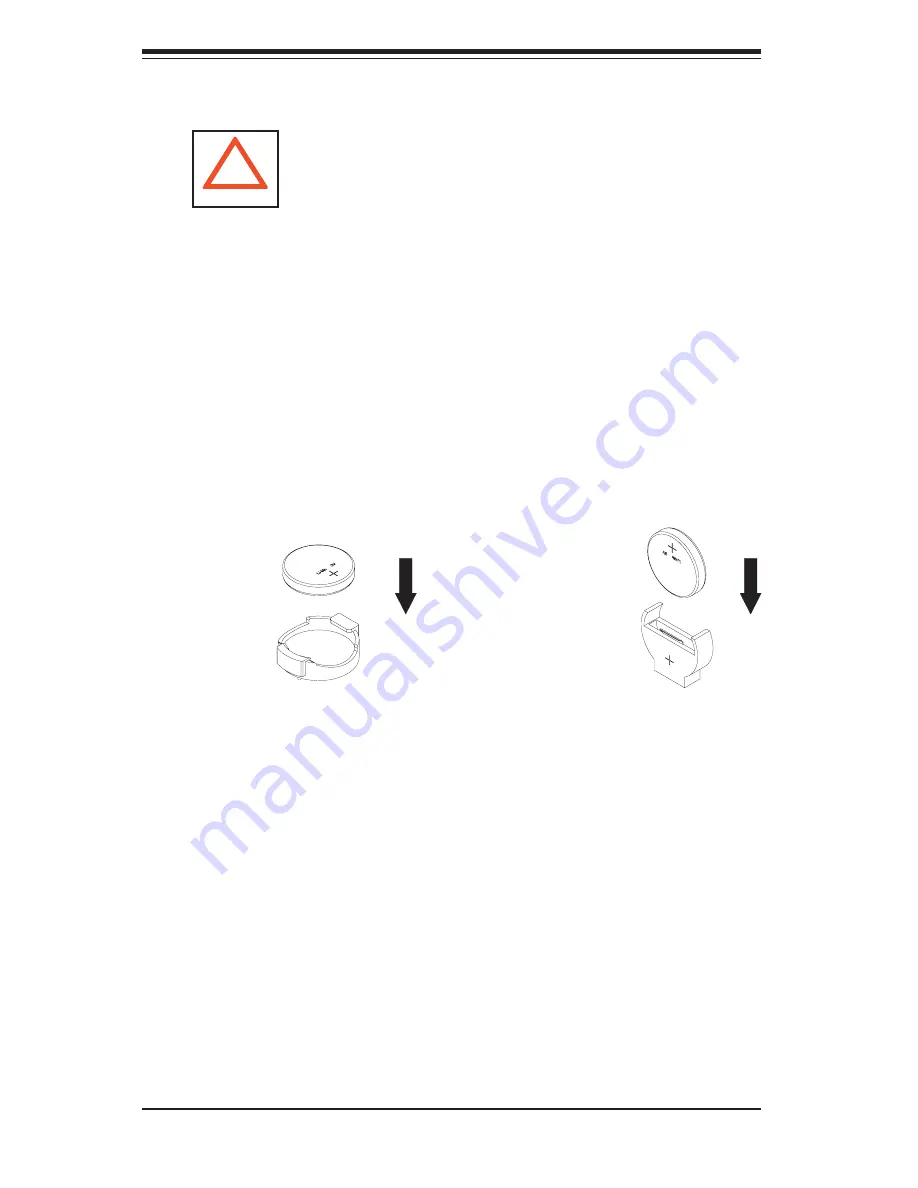
Figure 4-1. Installing the Onboard Battery

LITHIUM BATTERY

BATTERY HOLDER

BATTERY HOLDER

LITHIUM BATTERY

OR

Содержание SuperWorkstation 7044A-32

Страница 1: ...SUPERWORKSTATION 7044A 32 USER S MANUAL 1 0 SUPER...

Страница 2: ...PRODUCT OR DOCUMENTATION EVEN IF ADVISED OF THE POSSIBILITY OF SUCH DAMAGES IN PARTICULAR THE VENDOR SHALL NOT HAVE LIABILITY FOR ANY HARDWARE SOFTWARE OR DATA STORED OR USED WITH THE PRODUCT INCLUDIN...

Страница 3: ...ion The rst chapter provides a checklist of the main components included with the serv er system and describes the main features of the SUPER X6DA3 G2 serverboard and the SC743T 645 chassis which comp...

Страница 4: ...rs Refer to this chapter when adding or removing processors or main memory and when recon guring the serverboard Chapter 6 Advanced Chassis Setup Refer to Chapter 6 for detailed information on the SC7...

Страница 5: ...v Preface Notes...

Страница 6: ...lling the System into a Rack 2 4 2 5 Checking the Serverboard Setup 2 8 2 6 Checking the Drive Bay Setup 2 9 Chapter 3 System Interface 3 1 Overview 3 1 3 2 Control Panel Buttons 3 1 Power 3 1 Reset 3...

Страница 7: ...eference 5 11 5 8 Connector De nitions 5 12 ATX Power Connector 5 12 Processor Power Connector 5 12 NMI Button 5 12 Power LED 5 13 HDD LED 5 13 NIC LEDs 5 13 Overheat Fan Fail LED OH 5 13 Power Fail L...

Страница 8: ...2 5 11 Parallel Port Floppy Hard Disk Drive and SAS Connections 5 23 Parallel Port Connector 5 23 Floppy Connector 5 24 IDE Connectors 5 24 SAS Connectors 5 25 Chapter 6 Advanced Chassis Setup 6 1 Sta...

Страница 9: ...ble of Contents ix 7 4 Advanced Setup 7 7 7 5 Security 7 19 7 6 Boot 7 21 7 7 Exit 7 22 Appendices Appendix A BIOS POST Codes A 1 Appendix B Software Installation B 1 Appendix C System Speci cations C...

Страница 10: ...Notes x SUPERWORKSTATION 7044A 32 User s Manual...

Страница 11: ...ed for use with your workstation In addition to the serverboard and chassis various hardware components have been included with the SuperWorkstation as listed below One 1 3 5 oppy drive FPD PNSC 02 1...

Страница 12: ...which requires modules of the same size and speed to be installed in pairs SAS SATA A Serial Attached SCSI SAS Serial ATA SATA subsystem is provided with an Adaptec AIC 9410W controller which support...

Страница 13: ...a low noise level to make it ideal for use in a worksta tion environment SAS SATA Subsystem The SAS SATA subsystem supports up to eight SAS or SATA hard drives Any standard 3 5 drives are supported Th...

Страница 14: ...COM ports four USB 2 0 ports PS 2 mouse and keyboard ports two gigabit Ethernet ports and Line In Line Out and Microphone jacks see Figure 5 3 Cooling System The SC743T 645 chassis has an innovative...

Страница 15: ...X BUS 133M HZ G Bit LAN SLOT J 13 PCI X BUS 100M HZ J 14 1 PCI EXP SLOT J 17 PC I EXP B C X16 J 15 1 PCI EXP SLOT IDE PRI SEC X8 X4 X4 0 1 SATA SATA LPCBUS USB USB PORTS 0 1 2 3 BM C CON FWH LPC I O...

Страница 16: ...urope Address SuperMicro Computer B V Het Sterrenbeeld 28 5215 ML s Hertogenbosch The Netherlands Tel 31 0 73 6400390 Fax 31 0 73 6416525 Email sales supermicro nl General Information support supermic...

Страница 17: ...ip ahead to Section 2 5 2 2 Unpacking the System You should inspect the box the system was shipped in and note if it was damaged in any way If the server itself shows damage you should le a damage cla...

Страница 18: ...nding a component from the rack You should extend only one component at a time extending two or more simul taneously may cause the rack to become unstable Server Precautions Review the electrical and...

Страница 19: ...mised Mechanical Loading Equipment should be mounted into a rack so that a hazardous condition does not arise due to uneven mechanical loading Circuit Overloading Consideration should be given to the...

Страница 20: ...hat came with the rack unit you are using Identifying the Sections of the Rack Rails The optional rackmount kit CSE PT26 or CSE PT26B black includes two rack rail assemblies Each of these assemblies c...

Страница 21: ...r chassis rail sections you just removed along the side of the chassis making sure the screw holes line up Note that these two rails are left right speci c Screw the rail securely to the side of the c...

Страница 22: ...ed location in the rack keeping the sliding rail guide facing the inside of the rack Screw the assembly securely to the rack using the brackets provided Attach the other assembly to the other side of...

Страница 23: ...hese rst keeping in mind that they are left right speci c marked with L and R Then line up the rear of the chassis rails with the front of the rack rails Slide the chassis rails into the rack rails ke...

Страница 24: ...cessors You should have one or two processors already installed into the serverboard Each processor should have its own heatsink attached See Chapter 5 for instructions on processor installation 3 CPU...

Страница 25: ...reinstall a CD ROM and or oppy disk drive to the system 4 Check the SAS SATA disk drives Depending upon your system s con guration your system may have one or more drives already installed If you need...

Страница 26: ...2 10 SUPERWORKSTATION 7044A 32 User s Manual Figure 2 5 Accessing the Inside of the System Rack Con guration shown...

Страница 27: ...nents There are also two buttons on the chassis control panel 3 2 Control Panel Buttons There are two push button buttons located on the front of the chassis These are in order from left to right a po...

Страница 28: ...tivity On the 7044A 32 this LED indicates SAS SATA drive activity when ashing NIC1 Indicates network activity on LAN1 when ashing NIC2 Indicates network activity on LAN2 when ashing Overheat When this...

Страница 29: ...ot used with the SuperWorkstation 7044A 32 3 4 SAS SATA Drive LEDs Each SAS SATA drive carrier has a green LED When illuminated this green LED located on the front of the carrier indicates the drive i...

Страница 30: ...3 4 SUPERWORKSTATION 7044A 32 User s Manual Notes...

Страница 31: ...for SAS SATA drives When disconnecting power you should rst power down the system with the operating system and then unplug the power cord from the power supply unit When working around exposed elect...

Страница 32: ...our body which are excellent metal conductors that can create short circuits and harm you if they come into contact with printed circuit boards or areas where power is present After accessing the insi...

Страница 33: ...l components and printed circuit boards PCBs in their antistatic bags until ready for use Touch a grounded metal object before removing the board from the antistatic bag Do not let components or PCBs...

Страница 34: ...chassis covers are in place when the SuperWorkstation 7044A 32 is operating to ensure proper cooling Out of warranty damage to the 7044A 32 system can occur if this practice is not strictly followed...

Страница 35: ...at the size and weight of the serverboard can cause it to bend if handled improperly which may result in damage To prevent the serverboard from bending keep one hand under the center of the board to s...

Страница 36: ...CPU socket when power is applied Install CPU1 rst IMPORTANT Always connect the power cord last and always remove it before add ing removing or changing any hardware components Make sure that you insta...

Страница 37: ...e screws to avoid possible damage to the CPU The screw in the other two diagonal screws until snug 4 Finish the installation by fully tight ening all four screws Figure 5 1 604 pin PGA Socket Empty an...

Страница 38: ...e as show in the picture on the right 2 Hold the heatsink as show in the pic ture on the right and gently wriggle the heatsink to loosen it from the CPU Do not use excessive force when wriggling the h...

Страница 39: ...s connect to the pin 1 locations If you are con guring the system keep the air ow in mind when routing the cables The following data cables with their motherboard connector locations noted should be c...

Страница 40: ...h header All JF1 wires have been bundled into single ribbon cable to simplify their connection Make sure the red wire plugs into pin 1 as marked on the board The other end connects to the Control Pane...

Страница 41: ...o note that the memory is inter leaved to improve performance see step 1 DIMM Installation See Figures 5 4 and 5 5 1 Insert the desired number of DIMMs into the memory slots starting with Bank 1A The...

Страница 42: ...ntly push each release tab outward to free the DIMM from the slot Note Notch should align with the receptive point on the slot Notch Notch Release Tab Release Tab DIMMII Memory Support The X6DA3 G2 ha...

Страница 43: ...card support 2 PCI card installation Before installing a PCI add on card make sure you install it into a slot that supports the speed of the card see step 1 above Begin by removing the screw from the...

Страница 44: ...9 USB0 3 J32 J1B4 ATX Power J1D1 JSLED1 JSM2 JSM1 IPMI AIC 9410W PXH BIOS SATA1 SATA0 Slot 1 PCI X 100 MHz ZCR Slot 2 PCI X 100 MHz Slot 3 PCI X 133 MHz Slot 4 PCI Exp x4 Slot 5 PCI 33 MHz GLAN Cntrl...

Страница 45: ...n ATX Power Connector J1D1 J32 12V 8 pin and 12V 4 pin CPU Power Connectors J9 Keyboard Mouse Ports J22 System Management Bus Connector J24 Power System Management Bus I2 C JAR Power Fail Alarm Reset...

Страница 46: ...r at J1D1 must also be connected to your power supply See the table on the right for pin de nitions Required Connection NMI Button The non maskable interrupt button header is located on pins 19 and 20...

Страница 47: ...nd SCSI Disk Drives connection is located on pins 13 and 14 of JF1 Attach the hard drive LED cable to these pins to display disk activity Refer to the table on the right for pin de nitions Power Fail...

Страница 48: ...end mode depress the button for at least 4 seconds Refer to the table on the right for pin de nitions Reset Button The Reset Button connection is lo cated on pins 3 and 4 of JF1 Attach it to the hardw...

Страница 49: ...USB 2 0 Universal Serial Bus ports headers on the serverboard Four of them are back panel USB ports USB0 3 and the other four are front panel USB head ers USB4 5 and USB6 7 See the tables on the righ...

Страница 50: ...Wake On Ring card and cable to use this feature Wake On LAN The Wake On LAN header is located at JWOL on the motherboard See the table on the right for pin de nitions You must enable the LAN Wake Up...

Страница 51: ...upplies Alarm Reset If three power supplies are installed and the 3rd Power Supply Fail jumper J3P is enabled the system will no tify you when any of the three power modules fails Connecting JAR to a...

Страница 52: ...right for pin de nitions Green Line Out front L R Pink MIC center subwoofer Blue Line In surround L R CD Connectors Two CD connectors CD1 CD2 are located next to PCI slot 5 See the tables on the righ...

Страница 53: ...pers Closed means the jumper is on and Open means the jumper is off the pins Connector Pins Jumper Cap Setting Pin 1 2 short 3 2 1 3 2 1 CMOS Clear JBT1 is used to clear CMOS which will also clear any...

Страница 54: ...Enabled 2 3 Disabled SAS Controller Enable Jumper Settings JPS1 Jumper Setting De nition Pins 1 2 Enabled Pins 2 3 Disabled SAS Controller Enable Disable JPS1 enables or disables the AIC 9140W SAS con...

Страница 55: ...Watch Dog must also be enabled via BIOS Note When enabled the user needs to write his own application software in order to disable the Watch Dog Timer Watch Dog Jumper Settings JWD Jumper Setting De n...

Страница 56: ...ions associated with this second LED GLAN Connection Speed LED LED Color De nition Off No Connection Green 10 100 Mbps Orange 1 Gbps SAS Activity LEDs There are eight SAS Activity LEDs on the X6DA3 G2...

Страница 57: ...connector with twisted wires always connects to drive A and the connector that does not have twisted wires always connects to drive B Parallel Printer Port Connector The parallel printer port is locat...

Страница 58: ...9 Ground 20 STEP 21 Ground 22 Write Data 23 Ground 24 Write Gate 25 Ground 26 Track 00 27 Ground 28 Write Protect 29 Ground 30 Read Data 31 Ground 32 Side 1 Select 33 Ground 34 Diskette IDE Drive Conn...

Страница 59: ...nector Pin De nitions JSM1 JSM2 Pin De nition Pin De nition A1 Ground B1 Ground A2 RX 0 B2 TX 0 A3 RX 0 B3 TX 0 A4 Ground B4 Ground A5 RX 1 B5 TX 1 A6 RX 1 B6 TX 1 A7 Ground B7 Ground A8 SB7 B8 SB0 A9...

Страница 60: ...5 26 SUPERWORKSTATION 7044A 32 User s Manual Notes...

Страница 61: ...tant to handle them very carefully The following measures are generally suf cient to protect your equipment from static discharge Precautions Use a grounded wrist strap designed to prevent static disc...

Страница 62: ...6 2 SUPERWORKSTATION 7044A 32 User s Manual 8 SAS SATA Drive Bays Figure 6 1 Chassis Front View System Reset Main Power System LEDs Floppy Drive 5 25 Drive Bays 2 USB Ports...

Страница 63: ...to the control panel side of the chassis The LEDs on the control panel inform you of system status see Figure 6 2 for details See Chapter 5 for details on JF1 Figure 6 2 Front Control Panel LEDs Power...

Страница 64: ...fan housing Depress the locking tab on a chassis cooling fan and pull the unit straight out by the handle see Figure 6 3 The fan wiring for these fans has been designed to detach automatically 3 Inst...

Страница 65: ...Chapter 6 Advanced Chassis Setup 6 5 Figure 6 4 Removing the Air Shroud Figure 6 3 Removing a Chassis Fan...

Страница 66: ...hese carriers also work to promote proper air ow for the system For this reason even carriers without drives must remain in the server If you need to add a new SAS SATA drive insert the drive into the...

Страница 67: ...er 3 SAS SATA backplane All eight SAS SATA drives plug into a single SAS SATA backplane A ribbon cable from JA1 on the serverboard should be connected to the IN connector on the back plane There is al...

Страница 68: ...Then slide the CD ROM into the bay and secure it to the chassis with the drive carrier screws you rst removed Attach the power and data cables to the drive Replace the top left chassis cover before re...

Страница 69: ...ng and replacing the power supply unit for whatever reason Replacing the Power Supply 1 Accessing the power supply For safety reasons you will need to remove power from the system when replacing the p...

Страница 70: ...6 10 SUPERWORKSTATION 7044A 32 User s Manual Notes...

Страница 71: ...ack up battery provides power to the CMOS Memory in RTC Logic enabling it to retain system parameters Each time the computer is powered on the computer is con gured with the values stored in the CMOS...

Страница 72: ...ter turning the video on or 2 When the message shown below appears brie y at the bottom of the screen during the POST Power On Self Test press the Delete key to activate the main Setup menu Press the...

Страница 73: ...the correct data Press the Enter key to save the data BIOS Date This eld displays the date when this version of BIOS was built Legacy Diskette A This setting allows the user to set the type of oppy di...

Страница 74: ...the Non RAID driver Native Mode Operation Select the native mode for ATA The options are Parallel ATA Serial ATA Both and Auto IDE Channel 0 Master Slave IDE Channel 1 Master Slave IDE Channel 2 Mast...

Страница 75: ...nders This item indicates the status of Cylinders Headers This item indicates the number of headers Sectors This item displays the number of sectors Maximum Capacity This item displays the maximum sto...

Страница 76: ...ata to be transferred on both rising and falling edges of the clock doubling data throughput for any given clock speed The options are Disabled Mode 0 Mode 1 Mode 2 Mode 3 Mode 4 and Mode 5 Please ref...

Страница 77: ...ubmenu to make changes to the following settings Quick Boot Mode If enabled this feature will speed up the POST Power On Self Test routine by skipping certain tests after the computer is turned on The...

Страница 78: ...is received by your modem The options are On and Off Keyboard on Now Function This option allows you to select how the system may be resumed from the S3 S5 state The options are Space by pressing the...

Страница 79: ...CPU operations Select Uncached to disable this function Select Write Through to allow data to be cached into the system memory and into L1 L2 L3 cache area of the CPU at the same time Select Write Pro...

Страница 80: ...the user can achieve better graphic effects when using a Linux graphic driver that requires the write combining con guration with 4GB or more memory The options are Enabled and Disabled PCI Con gurat...

Страница 81: ...I X 66 MHz PCI X 100 MHz and PCI X 133 MHz PCI X 100MHz ZCR Slot 1 PCI X 100MHz Slot 2 PCI X 133MHz Slot 3 PCI E X4 Slot 4 PCI 33MHz Slot 5 PCI E X16 Slot 6 Access the submenu for each of the settings...

Страница 82: ...ources will overlap with the physical memory if 4GB of memory or above is installed on the motherboard When this occurs enable this function to reallocate the overlapped physical memory to a location...

Страница 83: ...achine Checking and allow the CPU to detect and report hardware machine errors via a set of model speci c registers MSRs The options are Disabled or Enabled C1 Enhanced Mode Available when supported b...

Страница 84: ...GV1 GV3 are disabled If set to C States only the processor power will be controlled through CPU power states in the APCI setting I O Device Con guration Access the submenu to make changes to the foll...

Страница 85: ...the parallel port The options are 378 278 and 3BC Interrupt This setting allows you to select the IRQ interrupt request for the parallel port The options are IRQ5 and IRQ7 Mode This setting allows yo...

Страница 86: ...and 115 2K Console Type This setting allows you to choose from the available options to select the console type for console redirection The options are VT100 VT100 8bit PC ANSI 7bit PC ANSI VT100 VT...

Страница 87: ...g you of the event log capacity View DMI Event Log Highlight this item and press Enter to view the contents of the event log Event Logging This setting allows you to Enable or Disable event logging EC...

Страница 88: ...speed will be controlled by Pulse Width Modulation PWM Select 3 pin if your chassis came with 3 pin fan headers Select 4 pin if your chassis came with 4 pin fan headers Select Workstation if your syst...

Страница 89: ...ord has been entered for the system Clear means such a password has not been used and Set means a supervisor password has been entered for the system User Password Is This displays whether a user pass...

Страница 90: ...allows access to the system at boot up Fixed Disk Boot Sector This setting may offer some protection against viruses when set to Write Protect which protects the boot sector on the hard drive from ha...

Страница 91: ...peci c Help window All Boot BIOS settings are described in this section Removable Devices Highlight and press Enter to expand the eld See details on how to change the order and specs of devices in the...

Страница 92: ...utility Exit Discarding Changes Highlight this item and hit Enter to exit the BIOS Setup utility without saving any changes you may have made Load Setup Defaults Highlight this item and hit Enter to l...

Страница 93: ...ort 80h The following is a list of codes that may be written to port 80h Appendix A BIOS POST Codes POST Code Description 02h Verify Real Mode 03h Disable Non Maskable Interrupt NMI 04h Get CPU type 0...

Страница 94: ...38h Shadow system BIOS ROM 3Ah Auto size cache 3Ch Advanced con guration of chipset registers 3Dh Load alternate registers with CMOS values 41h Initialize extended memory for RomPilot 42h Initialize...

Страница 95: ...t 80h Disable onboard Super I O ports and IRQs 81h Late POST device initialization 82h Detect and install external RS232 ports 83h Con gure non MCD IDE controllers 84h Detect and install external para...

Страница 96: ...nate QuietBoot optional B6h Check password optional B7h Initialize ACPI BIOS B9h Prepare Boot BAh Initialize SMBIOS BBh Initialize PnP Option ROMs BCh Clear parity checkers BDh Display MultiBoot menu...

Страница 97: ...size EEh Shadow Boot Block EFh System memory test F0h Initialize interrupt vectors F1h Initialize Run Time Clock F2h Initialize video F3h Initialize System Management Manager F4h Output one beep F5h C...

Страница 98: ...A 6 SUPERWORKSTATION 7044A 32 User s Manual Notes...

Страница 99: ...Note The onboard SAS Controller supports both SATA and SAS RAID con guration however mixing and matching SATA and SAS in the con guration is not recommended Using the Adaptec RAID Con guration Utilit...

Страница 100: ...select this option use the arrow keys and the enter key to select Managing Arrays from the main menu as shown above A Using the Array Con guration Utility TheArray Con guration Utility enables you to...

Страница 101: ...to prevent the loss of data Deleted arrays cannot be restored To delete an existing array 1 Turn on your computer and press Ctrl A when prompted to access the Adaptec RAID Con guration Utility 2 From...

Страница 102: ...ray 1 Turn on your computer and press Ctrl A when prompted to access the Adaptec RAID Con guration Utility 2 From the Adaptec RAID Con guration Utility menu select Array Con guration Utility Main Menu...

Страница 103: ...menu as shown in the screen below select an array type and press Enter Note that only the available array types RAID 0 and RAID1 are displayed on the screen RAID 0 or RAID 1 requires two drives 2 Unde...

Страница 104: ...5 When migrating from single volume to RAID 0 migrating from a larger drive to a smaller drive is allowed However the destination drive must be at least half the capacity of the source drive 6 Adaptec...

Страница 105: ...From the Main menu select Con gure Boot Unit and press Enter The following screen displays 2 From the Select Drive to Create Boot Unit list select the drive you wish to Con gure Boot Unit and press In...

Страница 106: ...Select the Boot Unit list in the right window select the bootable drive you wish to delete and press Delete The following screen appears 3 When the screen shown above appears select Delete and press...

Страница 107: ...ive 4 Use the up and down arrow keys to highlight and select the disk you want to des ignate as a Hotspare and press Insert and then press Enter 5 Press yes when the following prompt is displayed Do y...

Страница 108: ...g a disk overwrites the partition table on the disk and makes any data on the disk inaccessible If the drive is used in an array you may not be able to use the array again Do not initialize a disk tha...

Страница 109: ...en below select Initialize Drives and press Enter 4 From the Select drives for initialization list on the left screen select the disk you wish to initialize and press Insert The drive you ve selected...

Страница 110: ...d are selected and press En ter 6 When the following message appears make sure that you have selected the correct drive for initialization and press Y to initialize the drive or press N to quit Warnin...

Страница 111: ...rform a Rebuild to get the array to Optimal status For a critical array Rebuild operation the optimal drive is the source drive Note 2 If no spare array exists and a hard disk drive fails you need to...

Страница 112: ...y enables you to con gure SAS disk drive settings To access the SAS utilities 1 Turn on your computer and press Ctrl A when prompted to access the Adaptec RAID Con guration Utility as shown in the scr...

Страница 113: ...press F6 Note The default setting for each item is listed below Runtime BIOS Enabled BBS Support Device POST Banner Display Enabled CTRL A Message Display Enabled Physical Drives Display during POST E...

Страница 114: ...SerialSelect Utility and press Enter to access the Physical Con guration submenu as shown below 3 Select Physical Con guration and press Enter to access SAS Device Con gu ration submenu as shown below...

Страница 115: ...nu select Disk Utilities from the screen as shown above and press Enter 3 When the submenu appears select the desired disk and press Enter The following options are available 1 Format Disk Simulates a...

Страница 116: ...on gurations press ESC to exit The fol lowing screen will appear 2 Press Yes to exit the Utility For more information regarding Adaptec RAID Utility please refer to Adaptec s User s Guide in the CD in...

Страница 117: ...CD g Press the F6 key when the message Press F6 if you need to install a third party SCSI or RAID driver displays h When the Windows OS Setup screen appears press S to specify additional device s i In...

Страница 118: ...I driver diskettes which are optional The bottom icon with a CD on it allows you to view the entire contents of the CD Please refer to the Adaptec User s Guide for the installation of Adaptec s Serial...

Страница 119: ...Doctor III program included on the CDROM that came with your motherboard allows you to monitor the environment and operations of your system Supero Doctor III displays crucial system information such...

Страница 120: ...aded from our Web site at ftp ftp supermicro com utility Supero_Doctor_III You can also download SDIII User s Guide at http www supermicro com PRODUCT Manuals SDIII UserGuide pdf For Linux we will sti...

Страница 121: ...y Eight 240 pin DIMM sockets supporting up to 16 GB of registered ECC DDR2 400 PC3200 SDRAM Note Interleaved memory requires memory to be installed two at a time See the memory section in Chapter 5 fo...

Страница 122: ...4 hot swap 8 cm chassis PWM cooling fans One 1 air shroud System Input Requirements AC Input Voltage 100 240 VAC Rated Input Current 11A 90V Rated Input Frequency 50 to 60 Hz Power Supply Rated Output...

Страница 123: ...B EN 55022 Class A EN 61000 3 2 3 3 CISPR 22 Class B Electromagnetic Immunity EN 55024 CISPR 24 EN 61000 4 2 EN 61000 4 3 EN 61000 4 4 EN 61000 4 5 EN 61000 4 6 EN 61000 4 8 EN 61000 4 11 Safety EN 60...

Страница 124: ...C 4 SUPERWORKSTATION 7044A 32 User s Manual Notes...

Отзывы: