Chapter 7: BIOS
7-19
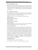
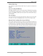
Hardware Monitor Logic
(See note on page 7-18.)
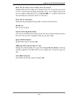
CPU Temperature Threshold
This option allows the user to set a CPU temperature threshold that will activate
the alarm system when the CPU temperature reaches this pre-set temperature
threshold. The hardcode default setting is
75
o
C
.
CPU1 Temperature/CPU1 Second Core
CPU2 Temperature/CPU2 Second Core
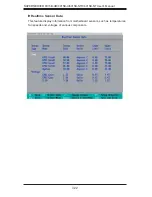
Temperature Monitoring (Available if supported by the CPU)
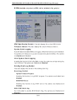
Highlight this and hit <Enter> to see monitor data for the following PECI (Platform
Environment Control Interface) items:
PECI Agent 1 Temperature
PECI Agent 2 Temperature
PECI Agent 3 Temperature
PECI Agent 4 Temperature
System Temperature
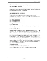
Fan1-Fan5 Speeds
: If the feature of Auto Fan Control is enabled, the BIOS will
automatically display the status of the fans indicated in this item.
Fan Speed Control Modes
This feature allows the user to decide how the system controls the speeds of the
onboard fans. The CPU temperature and the fan speed are correlative. When the
CPU on-die temperature increases, the fan speed will also increase, and vice versa.
If the option is set to 3-pin fan, the fan speed is controlled by voltage. If the option
is set to 4-pin, the fan speed will be controlled by Pulse Width Modulation (PWM).
Select 3-pin if your chassis came with 3-pin fan headers. Select 4-pin if your chas-
sis came with 4-pin fan headers. Select Workstation if your system is used as a
Workstation. Select Server if your system is used as a Server. Select Disable to
disable fan speed control and allow the onboard fans to constantly run at full speed
(12V). The Options are:
1. Disable
, 2. 3-pin (Server), 3. 3-pin (Workstation), 4.
4-pin (Server) and 5. 4-pin (Workstation).
Voltage Monitoring
The following items will be monitored and displayed:
Vcore A, Vcore B, -12V, P1V5, +3.3V, +12V, 5Vsb, 5VDD, P_VTT, Vbat
Содержание SUPERSERVER 6015B-NT
Страница 5: ...v Preface Notes...
Страница 10: ...Notes x SUPERSERVER 6015B UR 6015B U 6015B NTR 6015B NT User s Manual...
Страница 25: ...Chapter 2 Server Installation 2 9 Figure 2 5 Accessing the Inside of the System...
Страница 30: ...3 4 SUPERSERVER 6015B UR 6015B U 6015B NTR 6015B NT User s Manual Notes...
Страница 58: ...5 24 SUPERSERVER 6015B UR 6015B U 6015B NTR 6015B NT User s Manual Notes...
Страница 69: ...Chapter 6 Advanced Chassis Setup 6 11 Figure 6 6 Removing Replacing the Power Supply...
Страница 70: ...6 12 SUPERSERVER 6015B UR 6015B U 6015B NTR 6015B NT User s Manual Notes...
Страница 96: ...7 26 SUPERSERVER 6015B UR 6015B U 6015B NTR 6015B NT User s Manual Notes...
Страница 102: ...A 6 SUPERSERVER 6015B UR 6015B U 6015B NTR 6015B NT User s Manual Notes...
Страница 108: ...B 6 SUPERSERVER 6015B UR 6015B U 6015B NTR 6015B NT User s Manual Notes...
Страница 122: ...C 14 SUPERSERVER 6015B UR 6015B U 6015B NTR 6015B NT User s Manual Notes...
Страница 126: ...D 4 SUPERSERVER 6015B UR 6015B U 6015B NTR 6015B NT User s Manual Notes...

