Chapter 5: Advanced Serverboard Setup
5-17
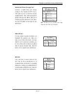
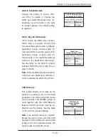
Redundant Power Supply Fail
Connect a cable from your power
supply to the header at J3P to pro-
vide warning of a redundant power
supply failure. This warning signal is
passed through the PWR_LED pin to
indicate a power failure on the chas-
sis. See the table on the right for pin
defi nitions.
Note:
This feature is only available when using
Supermicro redundant power supplies.
PWR Supply Fail Alarm
Pin Defi nitions (J3P)
Pin# Defi nition
1
PWR 1: Fail
2
PWR 2: Fail
3
PWR 3: Fail
4
Signal: Alarm Reset
Alarm Reset
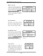
If three power supply modules are
installed, the system can notify you
when any of the three fails. Connect
JAR to a micro-switch to enable you
to turn off the alarm that is activated
when a power module fails. See the
table on the right for pin defi nitions.
Alarm Reset
Pin Defi nitions (JAR)
Pin Setting Defi nition
Pin 1
Ground
Pin 2
Alarm Reset
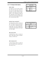
I-Button
The I- Button, located above the
LSI chip on the motherboard, is a
computer chip enclosed in a durable
stainless container to enable RAID 5
under Software RAID mode. See the
table on the right for pin defi nitions.
I-Button
Pin Defi nitions
Pin# Defi nition
1
Ground
2
GPIO1
3
Ground
Содержание SUPERSERVER 5015B-M3
Страница 1: ...SUPER USER S MANUAL Revision 1 0 SUPERSERVER 5015B M3...
Страница 5: ...v Preface Notes...
Страница 10: ...Notes SUPERSERVER 5015B M3 User s Manual x...
Страница 16: ...1 6 SUPERSERVER 5015B M3 User s Manual Notes...
Страница 30: ...3 4 SUPERSERVER 5015B M3 User s Manual Notes...
Страница 60: ...5 26 SUPERSERVER 5015B M3 User s Manual Notes...
Страница 68: ...6 8 SUPERSERVER 5015B M3 User s Manual Notes...
Страница 92: ...A 2 SUPERSERVER 5015B M3 User s Manual Notes...

