SC512 Chassis Manual
6-10
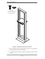
Figure 6-7: Installing the Server into a Telco Rack
SCALE 1:2
SCALE 1:2
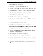
Hold the chassis in the telco rack and screw the chassis to the rack using the
3.
three screw holes located in the chassis ears.
The chassis is held in place by the chassis ears and does not slide in and out
4.
of place.
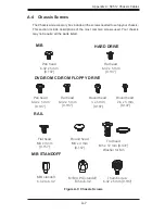
Flat head
M4 x 4 mm
[0.157]
RAIL
Round head
M4 x 4 mm
[0.157]
Flat head
M5 x 12 mm [0.472]
Washer for M5
DVD-ROM CD-ROM FLOPPY DRIVE
Flat head
6-32 x 5 mm
[0.197]
Pan head
6-32 x 5 mm
[0.197]
Round head
3 x 5 mm
[0.197]
Pan head
6-32 x 5 mm
[0.197]
M/B
Flat head
6-32 x 5 mm
[0.197]
HARD DRIVE
Thumb screw
6-32 x 5 mm [0.197]
M/B standoff
6-32 to 6-32
M/B STANDOFF
M/B (CPU) standoff
M5 to 6-32
Round head
2.6 x 5 mm
[0.197]
Содержание SC512C-260 Series
Страница 8: ...SC512 Chassis Manual viii Notes...
Страница 24: ...SC512 Chassis Manual 3 8 Notes...
Страница 28: ...SC512 Chassis Manual 4 4 Notes...
Страница 44: ...SC512 Chassis Manual 5 16 Notes...
Страница 51: ...6 7 Chapter 6 Rack Installation SCALE 0 380 Figure 6 4 Installing the Outer Rails to the Server Rack 3 3 2...
Страница 62: ...SC512 Chassis Manual A 8 Notes...
Страница 65: ...B 3 Appendix B SC512F Power Supply Specifications Notes...

