Supero SBI-7226T-T2 Скачать руководство пользователя страница 55

6-3

Chapter 6: BIOS

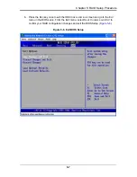
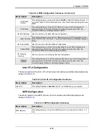
CPU & Clock Configuration

The menu options in the CPU C

ONFIGURATION

 submenu and their descriptions are 

shown in 

Table 6-1

.

Table 6-1. CPU Configuration Submenu 

Menu Option

Description

CPU Settings (Static)

This menu displays static information for Module Version, Manufacturer, 
Frequency, BCLK Speed, Cache L1, Cache L2, Cache L3, Ratio Status and 
Ratio Actual Value.

Ratio CMOS Setting

This setting sets the ratio between CPU Core Clock and the FSB Frequency. The 
default is 

20

.

Hardware Prefetcher

For UP platorms leave this setting enabled. For DP/MP servers, you can use this 
setting to tune performance to the specific application.Settings are 

Enabled

 and 

Disabled.

Adjacent Cache Line 
Prefetch

For UP platorms leave this setting enabled. For DP/MP servers, you can use this 
setting to tune performance to the specific application.Settings are 

Enabled

 and 

Disabled.

MPS and ACPI 
MADT Ordering

This setting specifies either M

ODERN

 O

RDERING

 for Windows XP or later OS’s or 

Legacy Ordering

 for Windows 2000 or earlier OS’s.

Max CPUID Value 
Limit

This setting is disabled for WindowsXP. Settings are Enabled and 

Disabled

.

Intel (R) Virtualization 
Tech

When enabled, a VMM can utilize the additional HW Caps that are provided by 
Intel Virtualization Technology. Settings are 

Enabled

 and Disabled.

NOTE: 

A full reset is required to change this setting.

Execute-Disable Bit 
Capability

When disabled, this setting forces the XD feature flag to always return to 0. 
Settings are 

Enabled

 and Disabled.

Intel (R) HT 
Technology

When Disabled, only one thread per enabled core is enabled. Settings are 

Enabled

 and Disabled.

Active Processor 
Cores

This setting specifies the number of cores in each processor package to activate. 
Settings are 

All

, 1 or 2.

A20M

Legacy OSes and APs may need A20M enabled. Settings are Enabled and 

Disabled

.

Intel SpeedStep(tm) 
tech

Use this setting to enable or disable GV3. Settings are 

Enabled

 and Disabled.

Intel (R) TurboMode 
Tech

Turbo mode allows the processor cores to run faster than their marked frequency 
in specific conditions. Settings are 

Enabled

 and Disabled.

Intel (R) C-State tech

When enabled, the CPU idle is set to C2/C3/C4. Settings are 

Enabled

 and 

Disabled.

C3 State

Use this setting to select the Nehalem C-state action. Settings are Disabled, 

ACPI C2

 and ACPI C3.

C6 State

Use this setting to enable or disable the Nehalem C6 state action. Settings are 

Enabled

 and Disabled.

C State Package 
Limit Setting

Use this setting to select the option that will program into C State the package 
limit register. Settings include 

Auto

, C1, C3, C6 and C7.

Содержание SBI-7226T-T2

Страница 1: ...SBI 7226T T2 Blade Module User s Manual Revison 1 0a...

Страница 2: ...resolution of any such disputes Super Micro s total liability for all claims will not exceed the price paid for the hardware product FCC Statement This equipment has been tested and found to comply wi...

Страница 3: ...and servicing the SBI 7226T T2 Blade Module Chapter 3 Setup and Installation Refer to this chapter for details on installing the SBI 7226T T2 Blade Module into the SuperBlade chassis Other sections co...

Страница 4: ...SBI 7226T T2 Blade Module User s Manual iv Notes...

Страница 5: ...3 1 3 1 Overview 3 1 3 2 Installing Blade Modules 3 1 Powering Up a Blade Unit 3 1 Powering Down a Blade Unit 3 1 Removing a Blade Unit from the Enclosure 3 1 Removing Replacing the Blade Cover 3 2 I...

Страница 6: ...n Utilities 5 2 5 2 BIOS Setup 5 2 Chapter 6 BIOS 6 1 6 1 Introduction 6 1 Running Setup 6 1 6 2 Main BIOS Setup Menu 6 1 System Time System Date 6 2 6 3 Advanced Settings Menu 6 2 CPU Clock Configura...

Страница 7: ...Configuration 6 12 System Health Monitor 6 13 6 4 Boot Menu 6 13 6 5 Security Menu 6 14 6 6 Exit Menu 6 15 Appendix A BIOS POST Codes A 1 A 1 BIOS POST Messages A 1 A 2 BIOS POST Codes A 3 Recoverabl...

Страница 8: ...SBI 7226T T2 Blade Module User s Manual viii Notes...

Страница 9: ...talling a Hard Drive in a Carrier 3 10 Figure 4 1 SBI 7226T T2 Blade Unit Front View 4 1 Figure 4 2 Blade Control Panel 4 2 Figure 4 3 B8DTT Mainboard 4 5 Figure 4 4 Intel 5500 IOH 24D Tylersburg ICH1...

Страница 10: ...SBI 7226T T2 Blade Module User s Manual x Notes...

Страница 11: ...ubmenu 6 6 Table 6 6 CPU Bridge Configuration Submenu 6 7 Table 6 7 NorthBridge Configuration Submenu 6 7 Table 6 8 SouthBridge Configuration Submenu 6 8 Table 6 9 ACPI Configuration Submenu 6 9 Table...

Страница 12: ...SBI 7226T T2 Blade Module User s Manual xii Notes...

Страница 13: ...power supplies and modules are housed in Please refer to our web site for information on operating systems that have been certified for use with the SuperBlade www supermicro com products superblade...

Страница 14: ...support up to 16 GB of ECC Unbuffered DDR3 1333 1066 800 SDRAM or 64 GB of ECC Registered DDR3 1333 1066 800 SDRAM DIMMs Both interleaved and non interleaved memory are supported so you may populate...

Страница 15: ...front mounted easy removable carriers two for each node See Chapter 3 Setup and Installation on page 3 1 for storage installation details Density A maximum of ten blade modules may be installed into...

Страница 16: ...SBI 7226T T2 Blade Module User s Manual 1 4 Figure 1 1 Full Rack of Blade Enclosures and Blade Servers...

Страница 17: ...per Micro Computer B V Het Sterrenbeeld 28 5215 ML s Hertogenbosch The Netherlands Tel 31 0 73 6400390 Fax 31 0 73 6416525 Email sales supermicro nl General Information support supermicro nl Technical...

Страница 18: ...SBI 7226T T2 Blade Module User s Manual 1 6 Notes...

Страница 19: ...oards they come into contact with Do not use mats designed to decrease electrostatic discharge as protection from electrical shock Instead use rubber mats that have been specifically designed as elect...

Страница 20: ...erated by two objects with different electrical charges coming into contact with each other An electrical discharge is created to neutralize this difference which can damage electronic components and...

Страница 21: ...unit is in place when the blade is operating to assure proper cooling Out of warranty damage to the blade can occur if this practice is not strictly followed Any drive carrier without a hard drive ins...

Страница 22: ...SBI 7226T T2 Blade Module User s Manual 2 4 Notes...

Страница 23: ...owering Down a Blade Unit A blade unit may be powered down in either of five ways Press the power button on the blade unit Use IPMIView or the web browser based management utility to power down if you...

Страница 24: ...e cover toward the front of the blade to lock it into place Installing a Blade Unit into the Enclosure Make sure the cover of the blade unit has been replaced first before installing a blade unit in t...

Страница 25: ...3 3 Chapter 3 Setup and Installation Figure 3 1 Inserting a Blade into the Enclosure Figure 3 2 Locking the Blade into Position...

Страница 26: ...ssor socket up until the processor is released from the socket then lift the silver cover plate and remove the processor Installing a Processor 1 If present remove the protective black PnP cap from th...

Страница 27: ...to supply certain volatile memory components with power when power has been removed from the blade module If this battery dies it must be replaced with an equivalent CR2032 Lithium 3V battery Dispose...

Страница 28: ...type will result in three channel interleaved memory which is faster than single channel non interleaved memory See Table 3 1 and Figure 3 5 for details For an interleaved configuration memory module...

Страница 29: ...8 Slot DIMM Numbering Edge of Board Toward CPU Toward CPU Edge of Board Toward CPU Toward CPU P2 DIMM1A P2 DIMM1B P2 DIMM2 P2 DIMM2 P3 DIMM2 P3 DIMM3 P3 DIMM1A P3 DIMM1B P4 DIMM1A P4 DIMM1B P4 DIMM2...

Страница 30: ...3 6 Installing a DIMM into a Memory Slot 4 Gently press down on the DIMM until it snaps into place in the slot Repeat for all modules see Table 3 1 for installing DIMMs into the slots in the correct o...

Страница 31: ...g a Hard Drive 1 Remove a blank drive carrier from the blade see removal procedure above 2 Insert a 2 5 drive into the carrier with the PCB side facing down and the connector end toward the rear of th...

Страница 32: ...SBI 7226T T2 Blade Module User s Manual 3 10 Figure 3 7 Installing a Hard Drive in a Carrier...

Страница 33: ...a mouse to the USB hub You will also need to connect a monitor to the video connector on the SUV cable Turn on the blade module 3 Insert the CD containing the OS into the CD ROM drive 4 Follow the pr...

Страница 34: ...ent may be performed with either of three software packages IPMIview SuperBladeTool or a Web based Management Utility These are designed to provide an administrator with a comprehensive set of functio...

Страница 35: ...ts Dual 1366 pin LGA Socket processors for up to two Intel 64 bit quad core Xeon series processors Memory Supports up to 64 GB of ECC Registered DDR3 1333 1066 800 SDRAM DIMMs or 16 GB of ECC Unbuffer...

Страница 36: ...s blade module on and off 2 KVM Button N A Initiates KVM function 3 Power LED Green Indicates power status On Orange Indicates power status Off with power cables plugged in 4 KVM UID LED Blue Indicate...

Страница 37: ...o switch to another blade disconnect the cable then reconnect it to the new blade See the Web based Management Utility User s Manual on your SuperBlade system CD ROM for further details on using the K...

Страница 38: ...he SBI 7226T T2 blade unit is a proprietary design which is based on the Intel 5500 IOH 24D Tylersburg ICH10R chipset See Figure 4 4 for a block diagram of this chipset Figure 4 3 for a view of the B8...

Страница 39: ...4 5 Chapter 4 Blade Module Features Figure 4 3 B8DTT Mainboard 2 6 7 3 6 5 5 9 1 4 5 5 8 8 7 9 10 10 11 11 12 12 14 14 13 13...

Страница 40: ...ocket 4 CPU4 Socket 5 DIMM Slots see Figure 3 5 8 Slot DIMM Numbering on page 3 7 for details 6 Space for 2 5 SATA Hard Drive 7 Gbx Connector for power and logic to backplane 8 BIOS Chip 9 Onboard Bat...

Страница 41: ...clear CMOS and will also clear any passwords JBT1 consists of two contact pads located near the BIOS chip 10 in Figure 4 3 PROCESSOR 0 PROCESSOR 1 1 DDR3 DIMM 2 DDR3 DIMM 1 1 1 DDR3 DIMM 2 DDR3 DIMM...

Страница 42: ...access the mainboard see Section Removing Replacing the Blade Cover on page 3 2 for further details Short the CMOS pads with a metal object such as a small screwdriver 3 Replace the cover install the...

Страница 43: ...The four drives can be used to set up a RAID array SATA RAID 0 or 1 only or JBOD These drives use a yellow color for the Blade HDD active LED Table 4 5 Main Components of SBI 7226T T2 Blade Unit Item...

Страница 44: ...SBI 7226T T2 Blade Module User s Manual 4 10...

Страница 45: ...e ACU you can restart it by pressing CTRL R NOTE A RAID 1 created using the QUICK INIT option may return some data miscompares if you later run a consistency check This is normal and is not a cause fo...

Страница 46: ...e of these utilities see the SuperMicro website at http www supermicro com support manuals for these RAID Installation Guides 5 2 BIOS Setup Use the BIOS setup to configure for either the Intel or Ada...

Страница 47: ...5 2 select the SATA drives you wish to configure as RAID drives For each drive select the CONFIGURE SATA AS menu option and select the RAID option for it The screen will change to reflect your change...

Страница 48: ...SBI 7226T T2 Blade Module User s Manual 5 4 3 In the changed IDE CONFIGURATION screen select the MAX PORTS ON SATA option and set your ports selection Figure 5 3 Figure 5 3 Selecting Max Ports Option...

Страница 49: ...5 5 Chapter 5 RAID Setup Procedure 4 For the RAID ID Support menu option Figure 5 4 select either the Intel or Adaptec utility for configuring your RAID configuration Figure 5 4 Selecting RAID Utility...

Страница 50: ...7226T T2 Blade Module User s Manual 5 6 5 The last option is for enabling or disabling Hot Plug support for your RAID configuration using the HOT PLUG menu option Figure 5 5 Figure 5 5 Enabling Hot P...

Страница 51: ...Esc key once to exit the IDE CONFIGURATION screen and go to the EXIT menu in the BIOS setup From the Exit menu select SAVE CHANGES AND EXIT to confirm your RAID configuration changes and exit the BIO...

Страница 52: ...le User s Manual 5 8 7 Your system will reboot When the reboot displays the screen message in Figure 5 7 press CTRL A to bring up the RAID Configuration Utility you chose in step 4 Intel or Adaptec Fi...

Страница 53: ...he message Press the Delete key to enter Setup appears briefly at the bottom of the screen during the POST press the DELETE key to activate the main SETUP menu 6 2 Main BIOS Setup Menu The MAIN MENU s...

Страница 54: ...ou can edit the SYSTEM TIME SYSTEM DATE field to change the system time and date Highlight SYSTEM TIME or SYSTEM DATE using the ARROW keys Enter new values through the keyboard Press the TAB key or th...

Страница 55: ...ilize the additional HW Caps that are provided by Intel Virtualization Technology Settings are Enabled and Disabled NOTE A full reset is required to change this setting Execute Disable Bit Capability...

Страница 56: ...ATA 1 Options include IDE RAID or AHCI Max Ports on SATA 1 Use this setting to specify the maximum ports on SATA 1 Options include 4 ports and 6 ports RAID ID Support If you have selected the RAID set...

Страница 57: ...graphics device is installed in the system in order for the graphics card to function properly The options are ENABLED and Disabled PCI IDE BusMaster When enabled this allows BIOS to use PCI busmaste...

Страница 58: ...nd IRQ 4 for the interrupt address Serial Port2 Address This option specifies the base I O port address and Interrupt Request address of serial port 2 The options are DISABLED 2F8 IRQ3 3E8 IRQ4 and 2E...

Страница 59: ...ponents Options include Auto 4 800GT 5 866GT and 6 400GT QPI L0s and L1 This setting allows you to Enable or Disable QPI L0s and L1 Memory Frequency This setting forces a DDR3 frequency slower than th...

Страница 60: ...egacy support if there are no USB devices installed in the system AUTO disables Legacy support if no USB devices are connected The options are DISABLED Enabled and AUTO USB 2 0 Controller Mode Select...

Страница 61: ...les the Headless operation mode through ACPI NUMA Support This setting Enables or Disables NUMA support Chipset ACPI Confguration Use this sub menu to confgure chipset ACPI related configuration setti...

Страница 62: ...ht this item and press ENTER to mark all events as read Clear Event Log Select Yes and press ENTER to clear all event logs The options are YES and NO to verify Table 6 12 IPMI Configuration Submenu Me...

Страница 63: ...of XX XX XX XX XX XX The current MAC Address is statically displayed below Subnet Mask Use this sub menu forSubnet Mask configuration Subnet Mask This setting allows you to set the Subnet Mask for you...

Страница 64: ...Menu Option Description Remote Access Allows you to Enable or Disable remote access If enabled the settings below will appear Serial Port Number Selects the serial port to use for console redirection...

Страница 65: ...nd KEEP CURRENT The default setting is Force BIOS Select Force BIOS to allow the computer system to force a third party BIOS to display during system boot Select KEEP CURRENT to allow the computer sys...

Страница 66: ...ves installed in your system 1st Drive These settings specify the boot sequence from the available hard disk drives devices installed in your system The devices to set are 1ST DRIVE 2ND DRIVE 3RD DRIV...

Страница 67: ...is option to quit BIOS Setup without making any permanent changes to the system configuration and reboot the computer Select DISCARD CHANGES AND EXIT from the EXIT menu and press ENTER Discard Changes...

Страница 68: ...SBI 7226T T2 Blade Module User s Manual 6 16 Notes...

Страница 69: ...4k block at which the error was detected System RAM Failed at offset nnnn System RAM failed at offset nnnn of in the 64k block at which the error was detected Extended RAM Failed at offset nnnn Extend...

Страница 70: ...n older boards check the cache jumpers You may have to replace the cache See your dealer A disabled cache slows system performance considerably CPU ID CPU socket number for Multi Processor error EISA...

Страница 71: ...cking errors in binary data A parity error indicates that some data has been corrupted Parity Check 2 nnnn Parity error found in the I O bus BIOS attempts to locate the address and display it on the s...

Страница 72: ...POST Errors Post Code Description 02h Verify Real Mode 03h Disable Non Maskable Interrupt NMI 04h Get CPU type 06h Initialize system hardware 07h Disable shadow and execute code from the ROM 08h Initi...

Страница 73: ...ize extended memory for RomPilot 42h Initialize interrupt vectors 45h POST device initialization 46h 2 1 2 3 Check ROM copyright notice 47h Initialize I20 support 48h Check video configuration against...

Страница 74: ...lize Intelligent System Monitoring 7Eh Initialize coprocessor if present 80h Disable onboard Super I O ports and IRQs 81h Late POST device initialization 82h Detect and install external RS232 ports 83...

Страница 75: ...pt AAh Scan for F2 key stroke ACh Enter SETUP AEh Clear Boot flag B0h Check for errors B1h Inform RomPilot about the end of POST B2h POST done prepare to boot operating system B4h 1 One short beep bef...

Страница 76: ...mory for PCMCIA CEh Initialize digitizer and display message D2h Unknown interrupt Table A 3 Boot Block Flash ROM Terminal POST Errors Post Code Description E0h Initialize the chipset E1h Initialize t...

Страница 77: ...in the lower 16 bits The BIOS also sends the bitmap to the port 80 LED display It first displays the checkpoint code followed by a delay the high order byte another delay and then the low order byte o...

Страница 78: ...SBI 7226T T2 Blade Module User s Manual A 10 Notes...

Страница 79: ...ted to result in significant injury or loss of life or catastrophic property damage Accordingly Supermicro disclaims any and all liability and should buyer use or sell such products for use in such ul...

Страница 80: ...SBI 7226T T2 Blade Module User s Manual...

Отзывы: