5-4
A+ SERVER 4042G-6RF/TRF User's Manual
5-4 I/O Ports
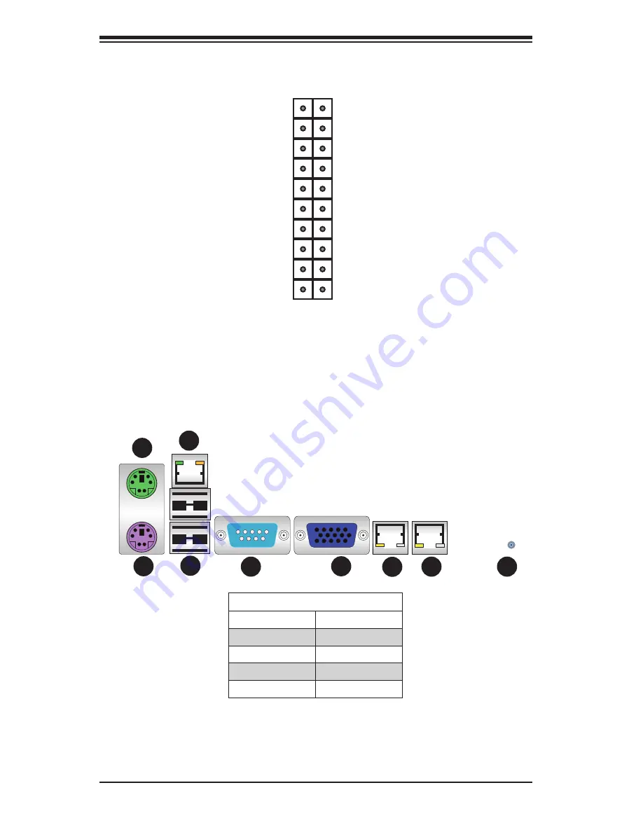
The I/O ports are color coded. See Figure 5-2 below for the colors and locations
of the various I/O ports.
Figure 5-1. Control Panel Header Pins
Figure 5-2. I/O Ports
Power
2 1
20 19
Ground
Key
Power LED
HDD LED
NIC1 (Link) LED
NIC2 (Link) LED
OH/Fan Fail/PWR Fail/UID LED
Power Fail LED
Ground
Ground
No Connection
Key
3.3V
Vcc
NIC1 (Activity) LED
NIC2 (Activity) LED
Vcc
3.3V
Reset
Rear I/O Ports
1. Keyboard
6. VGA Port
2. PS/2 Mouse
7. LAN1
3. USB0/1
8. LAN2
4. IPMI LAN
9. UID
5. COM1
1
9
8
7
6
5
4
3
2
Содержание A+ SERVER 2042G-6RF
Страница 1: ... SUPER A SERVER 4042G 6RF TRF USER S MANUAL Revision 1 0f ...
Страница 23: ...Chapter 2 Server Installation 2 9 Figure 2 5 Accessing the Inside of the System ...
Страница 28: ...3 4 4042G 6RF TRF User s Manual Notes ...
Страница 48: ...4 20 A SERVER 8027R TRF 7RFT User s Manual Notes ...
Страница 90: ...6 10 A SERVER 4042G 6RF TRF User s Manual Figure 6 7 Removing a Power Supply Module ...
Страница 108: ...A 2 A SERVER 4042G 6RF TRF User s Manual Notes ...


