


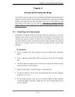


Chapter 5: Advanced Serverboard Setup
5-3
Rear I/O Ports
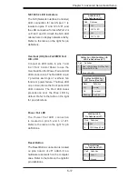
1. COM1 Port
2. USB0 Port
3. USB1 Port
4. Dedicated IPMI LAN Port
5. USB2 Port
6. USB3 Port
7. LAN1 Port
8. LAN2 Port
9. VGA Port
10. UID Switch
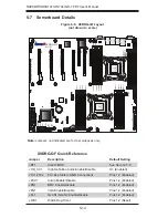
Figure 5-1. Control Panel Header Pins
5-3 I/O Ports
The I/O ports are color coded in conformance with the PC 99 specification. See
Figure 5-2 below for the colors and locations of the various I/O ports.
1
1
1
7
1
5
1
6
1
4
1
3
1
2
1
8
1
9
1
10
Figure 5-2. I/O Ports
Power Button
Blue+ (OH/Fan Fail/
PWR FaiL/UID LED)
1
NIC1 Link LED
Reset Button
2
Power Fail LED
HDD LED
FP PWRLED
Reset
PWR
3.3 V
ID_UID_SW/3/3V Stby
Red+ (Blue LED Cathode)
Ground
Ground
19
20
3.3V
X
Ground
NMI
X
NIC2 Link LED
NIC2 Activity LED
NIC1 Activity LED
Содержание 7047GR-TPRF
Страница 1: ...SuperWorkstation 7047GR TPRF SUPER USER S MANUAL Revision 1 0b...
Страница 5: ...v Preface Notes...
Страница 48: ...4 20 SUPERWORKSTATION 7047GR TPRF User s Manual Notes...
Страница 78: ...5 30 SUPERWORKSTATION 7047GR TPRF User s Manual Notes...
Страница 94: ...6 16 SUPERWORKSTATION 7047GR TPRF User s Manual Notes...
Страница 128: ...A 2 SUPERWORKSTATION 7047GR TPRF User s Manual Notes...
Страница 131: ...B 3 Appendix B System Specifications Notes...