background image

7-8

S

UPER

S

TORAGE

S

YSTEM 6047R-E1R24N User's Manual

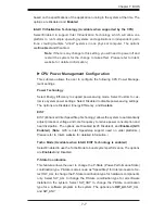
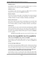
CPU C3 Report

Select Enabled to allow the BIOS to report the CPU C3 State (ACPI C2) to the 

operating system. During the CPU C3 State, the CPU clock generator is turned 

off. The options are Enabled and 

Disabled.

CPU C6 Report

Select Enabled to allow the BIOS to report the CPU C6 State (ACPI C3) to the 

operating system. During the CPU C6 State, the power to all cache is turned 

off. The options are Enabled and 

Disabled.

CPU C7 Report

Select Enabled to allow the BIOS to report the CPU C7 State (ACPI C3) to the 

operating system. CPU C7 State is a processor-specifi c low C-State. The options 

are Enabled and 

Disabled.

Package C-State limit

This feature allows the user to set the limit on the C-State package register. The 

options are 

C0

, C2, C6, and No Limit.

Factory Long Duration Power Limit

This item displays the power limit set by the manufacturer during which long 

duration power is maintained.

Long Duration Power Limit

This item displays the power limit set by the manufacturer during which long 

duration power is maintained.

Factory Long Duration Maintained

This item displays the period of time set by the manufacturer during which long 

duration power is maintained.

Recommended Short Duration Power

This item displays the short duration power settings recommended by the 

manufacturer. 

Short Duration Power Limit

This item displays the time period during which short duration power is main-

tained.

Содержание 6047R-E1R24N

Страница 1: ...SUPER STORAGE SYSTEM 6047R E1R24N SUPER USER S MANUAL 1 0a...

Страница 2: ...any such disputes Super Micro s total liability for all claims will not exceed the price paid for the hardware product FCC Statement This equipment has been tested and found to comply with the limits...

Страница 3: ...nd the SC846E16 R920B chassis Chapter 2 Server Installation This chapter describes the steps necessary to install the 6047R E1R24N into a rack and check out the server configuration prior to powering...

Страница 4: ...ig uring the serverboard Chapter 6 Advanced Chassis Setup Refer to Chapter 6 for detailed information on the SC846E16 R920B chassis You should follow the procedures given in this chapter when installi...

Страница 5: ...Notes Preface v...

Страница 6: ...paring for Setup 2 1 Choosing a Setup Location 2 1 2 4 Warnings and Precautions 2 2 Rack Precautions 2 2 Server Precautions 2 2 Rack Mounting Considerations 2 3 Ambient Operating Temperature 2 3 Reduc...

Страница 7: ...duct Disposal 4 15 Hot Swap Fan Warning 4 16 Power Cable and AC Adapter 4 18 Chapter 5 Advanced Serverboard Setup 5 1 Handling the Serverboard 5 1 Precautions 5 1 Unpacking 5 2 5 2 Connecting Cables 5...

Страница 8: ...6 4 Replacing System Fans 6 4 Rear Exhaust Fans 6 4 6 5 Drive Bay Installation Removal 6 5 Accessing the Drive Bays 6 5 SATA Drive Installation 6 6 Hard Drive Backplane 6 7 Removing the Air Shroud 6 8...

Страница 9: ...ww supermicro com In addition to the serverboard and chassis various hardware components have been included with the 6047R E1R24N as listed below Two passive CPU heatsinks SNK P0048P Three 8 cm system...

Страница 10: ...s LRDIMMs 16 modules max for UDIMMs See Chapter 5 for details Serial ATA A SATA controller is also integrated into the chipset to provide two SATA 3 6 Gbps and four SATA 2 3 Gbps ports which are RAID...

Страница 11: ...ATA drives Front Control Panel The control panel on the SuperServer 6047R E1R24N provides you with system monitoring and control LEDs indicate system power HDD activity network activ ity system overhe...

Страница 12: ...M BIOS CPU REAR CPU FRONT PEG1_8 PCI E x16 Slot USB REAR HDR 2X5 0 1 TPM HDR TYPE A REAR 2 3 QPI DDR3 DIMM B DDR3 DIMM D C H F E Socket 1 Socket 2 1 2 3 1 2 3 1 2 3 1 2 3 1 2 3 1 2 3 P0 P0 P1 P1 PE3 P...

Страница 13: ...P2 DIMMG2 P2 DIMMH2 P2 DIMMH3 COM1 USB6 7 UID IPMI_LAN Alaways populate DIMMx1 first P1 DIMMA2 P1 DIMMA1 P1 DIMMB3 P1 DIMMB2 P1 DIMMB1 P1 DIMMA3 P1 DIMMC1 P1 DIMMC2 P1 DIMMC3 P1 DIMMD1 P1 DIMMD2 P1 DI...

Страница 14: ...Europe Address Super Micro Computer B V Het Sterrenbeeld 28 5215 ML s Hertogenbosch The Netherlands Tel 31 0 73 6400390 Fax 31 0 73 6416525 Email sales supermicro nl General Information support superm...

Страница 15: ...Server 6047R E1R24N It should be situated in a clean dust free area that is well ventilated Avoid areas where heat electrical noise and electromagnetic fields are generated You will also need it place...

Страница 16: ...component from the rack You should extend only one component at a time extending two or more si multaneously may cause the rack to become unstable Server Precautions Review the electrical and general...

Страница 17: ...sible overloading of circuits might have on overcurrent protection and power supply wiring Appropriate consideration of equipment nameplate ratings should be used when addressing this concern Reliable...

Страница 18: ...sembly procedure will differ slightly You should also refer to the installation instructions that came with the rack unit you are using Note This rail will fit a rack between 27 and 34 45 deep Identif...

Страница 19: ...chas sis with the inner rail holes Make sure that the rail faces outward so that it will fit with the rack s mounting bracket 2 Slide the rail toward the front of the chassis 3 Secure the rail to the...

Страница 20: ...y into the rack 3 Secure the long bracket to the front side of the outer rail with two M5 screws and the short bracket to the rear side of the outer rail with three M5 screws 4 Repeat steps 1 4 for th...

Страница 21: ...2 Server Installation 2 7 Figure 2 4 Installing the Outer Rails to the Server Rack 1 3 1 3 1 2 Note Figures are for illustrative purposes only Servers should always be installed to the bottom of a rac...

Страница 22: ...assis rails A with the front of the rack rails B 3 Slide the chassis rails into the rack rails keeping the pressure even on both sides you may have to depress the locking tabs when inserting When the...

Страница 23: ...set button and a power on off button Reset Use the reset button to reboot the system Power This is the main power button which is used to apply or turn off the main system power Turning off system pow...

Страница 24: ...re When on continuously it indicates an overheat condition which may be caused by cables obstructing the airflow in the system or the ambient room temperature being too warm Check the routing of the c...

Страница 25: ...ting 3 4 Drive Carrier LEDs Each drive carrier has two LEDs Blue When illuminated the blue LED on the front of the drive carrier indicates drive activity A connection to the backplane enables this LED...

Страница 26: ...3 4 SUPERSTORAGESYSTEM 6047R E1R24N User s Manual Notes...

Страница 27: ...nt for assistance Only certified technicians should attempt to install or configure components Read this appendix in its entirety before installing or configuring components in the Supermicro chassis...

Страница 28: ...ipo considere los riesgos de la corriente el ctrica y familiar cese con los procedimientos est ndar de prevenci n de accidentes Al final de cada advertencia encontrar el n mero que le ayudar a encontr...

Страница 29: ...l kan veroorzaken Voordat u aan enige apparatuur gaat werken dient u zich bewust te zijn van de bij een elektrische installatie betrokken risico s en dient u op de hoogte te zijn van de standaard proc...

Страница 30: ...schlie en des Systems an die Stromquelle die Installationsanweisungen lesen Advertencia Lea las instrucciones de instalaci n antes de conectar el sistema a la red de alimentaci n Attention Avant de br...

Страница 31: ...ert ist Stellen Sie sicher dass der Nennwert der Schutzvorrichtung nicht mehr als 250 V 20 A betr gt Advertencia Este equipo utiliza el sistema de protecci n contra cortocircuitos o sobrecorrientes de...

Страница 32: ...ckgreift um Systemsbestandteile anzubringen oder zu entfernen Warning The system must be disconnected from all sources of power and the power cord removed from the power supply module s before accessi...

Страница 33: ...nentes de sistema Attention Le syst me doit tre d branch de toutes les sources de puissance ainsi que de son cordon d alimentation secteur avant d acc der l int rieur du chassis pour installer ou enle...

Страница 34: ...t Warnung Das Installieren Ersetzen oder Bedienen dieser Ausr stung sollte nur geschultem qualifiziertem Personal gestattet werden Advertencia Solamente el personal calificado debe instalar reemplazar...

Страница 35: ...stallation in Bereichen mit beschr nktem Zutritt vorgesehen Der Zutritt zu derartigen Bereichen ist nur mit einem Spezialwerkzeug Schloss und Schl ssel oder einer sonstigen Sicherheitsvorkehrung m gli...

Страница 36: ...he same or equivalent type recommended by the manufacturer Dispose of used batteries according to the manufacturer s instructions Waarschuwing Dit apparaat is bedoeld voor installatie in gebieden met...

Страница 37: ...ecommand e par le fabricant Jeter les piles usag es conform ment aux instructions du fabricant Advertencia Existe peligro de explosi n si la bater a se reemplaza de manera incorrecta Reemplazar la bat...

Страница 38: ...xi n para fuentes de alimentaci n Para cortar por completo el suministro de energ a deben desconectarse todas las conexiones Attention Cette unit peut avoir plus d une connexion d alimentation Pour su...

Страница 39: ...ero es peligroso Tenga cuidado cuando lo revise Attention Lorsque le syst me est en fonctionnement des tensions lectriques circulent sur le fond de panier Prendre des pr cautions lors de la maintenanc...

Страница 40: ...al electrical codes Warnung Die Installation der Ger te muss den Sicherheitsstandards entsprechen Advertencia La instalacion del equipo debe cumplir con las normas de electricidad locales y nacionales...

Страница 41: ...ional laws and regulations Attention L quipement doit tre install conform ment aux normes lectriques nationales et locales Waarschuwing Bij installatie van de apparatuur moet worden voldaan aan de lok...

Страница 42: ...debe seguir todas las leyes y reglamentos nacionales Attention La mise au rebut ou le recyclage de ce produit sont g n ralement soumis des lois et ou directives de respect de l environnement Renseigne...

Страница 43: ...dedos los destornilladores y todos los objetos lejos de las aberturas del ventilador Attention Il est possible que les ventilateurs soient toujours en rotation lorsque vous retirerez le bloc ventilat...

Страница 44: ...nd Adapter kann zu einer Fehlfunktion oder ein Brand entstehen Elektrische Ger te und Material Safety Law verbietet die Verwendung von UL oder CSA zertifizierte Kabel UL oder CSA auf der Code f r alle...

Страница 45: ...utres appareils lectriques que les produits d sign s par Supermicro seulement AC AC UL CSA UL CSA UL CSA Supermicro UL CSA AC Electrical Appliance and Material Safety Law UL CSA UL CSA Waarschuwing Bi...

Страница 46: ...4 20 SUPERSTORAGESYSTEM 6047R E1R24N User s Manual Notes...

Страница 47: ...to handle them very carefully see previous chapter To prevent the serverboard from bending keep one hand under the center of the board to support it when handling The following measures are generally...

Страница 48: ...d should be connected See the layout on page 5 10 for connector locations SATA drive data cables I SATA0 I SATA5 Control Panel cable JF1 USB cable for front side access USB4 5 Important Make sure the...

Страница 49: ...I O Ports NMI x Key 3 3V ID UID SW 3 3V Stby NIC1 Activity LED NIC2 Activity LED Red Blue Cathode 3 3V Reset Button Power Button Ground x Key Power On LED HDD LED NIC1 Link LED NIC2 Link LED OH Fan F...

Страница 50: ...hanging any hardware components Make sure that you install the processor into the CPU socket before you install the CPU heatsink If you buy a CPU separately make sure that you use an Intel certified m...

Страница 51: ...ARNING plastic cap from the socket 5 Use your thumb and index finger to hold the CPU by its edges Align the CPU keys which are semi circle cutouts against the socket keys 6 Once they are aligned caref...

Страница 52: ...te again and double check that the CPU is aligned properly 7 With the CPU in the socket in spect the four corners of the CPU to make sure that they are flush with the socket 8 Close the load plate Loc...

Страница 53: ...t has already been applied 2 Place the heatsink on top of the CPU so that the four mounting holes are aligned with those on the Serverboard s and the Heatsink Bracket underneath 3 Screw in two diagona...

Страница 54: ...board in the sequence as shown in the illustration below 2 Gently wriggle the heatsink to loosen it from the CPU Do not use excessive force when wriggling the heatsink 3 Once the heatsink is loosened...

Страница 55: ...ts slot Pay attention to the notch along the bottom of the module to avoid installing incorrectly see Figure 5 3 3 Use your thumbs to gently press down on both ends of the DIMM module until it snaps i...

Страница 56: ...MMA2 P1 DIMMB2 P1 DIMMC2 P1 DIMMD2 P1 DIMMA3 P1 DIMMB3 P1 DIMMC3 P1 DIMMD3 2 CPUs 4 DIMMs CPU1 CPU2 P1 DIMMA1 P1 DIMMB1 P2 DIMME1 P2 DIMMF1 2 CPUs 6 DIMMs CPU1 CPU2 P1 DIMMA1 P1 DIMMB1 P2 DIMME1 P2 DI...

Страница 57: ...supermicro com sup port resources mem cfm Intel E5 2600 Series Processor RDIMM Memory Support Table Ranks Per DIMM Data Width Memory Capacity Per DIMM See the Note Below Speed MT s and Voltage Valida...

Страница 58: ...333 1066 1066 Note For detailed information on memory support and updates please refer to the SMC Recom mended Memory List posted on our website at http www supermicro com support resources mem cfm Im...

Страница 59: ...1 CPU 12 DIMMs 1 CPU 6 DIMMs Rev 1 10 X9DR3 LN4F X9DRi LN4F Rev 1 10 X9DR3 LN4F X9DRi LN4F Rev 1 10 X9DR3 LN4F X9DRi LN4F Rev 1 10 X9DR3 LN4F X9DRi LN4F Rev 1 10 X9DR3 LN4F X9DRi LN4F Rev 1 10 X9DR3...

Страница 60: ...shield for the PCI slot you wish to populate 2 Fully seat the card into the slot pushing down with your thumbs evenly on both sides of the card 3 Finish by using a screw to secure the top of the card...

Страница 61: ...H1 FANB FANA FAN4 FAN3 FAN2 FAN6 FAN1 SW1 JPP1 JPP0 J21 JBT1 LEM1 JWP1 JPG1 JWD1 JPL1 JPME2 JPME1 USB4 5 JTPM1 XDP PCH in X8 Slot CPU2 Slot6 PCI E 3 0x8 CPU2 Slot5 PCI E 3 0 x16 CPU2 Slot4 PCI E 3 0 x...

Страница 62: ...Pins 1 2 Enabled Connector Description COM1 COM2 Backplane COM Port1 Front Accessible COM2 Header FAN1 6 FANA B CPU System Fan Headers IPMB 4 pin External BMC I2 C Header for an IPMI Card I SATA 0 5...

Страница 63: ...k Panel USB 2 3 USB 4 5 USB 6 7 Front Panel Accessible USB Connections 4 5 6 7 USB 9 Front Panel Type A USB 6 USB 7 Ports UID Switch UID Unit Identifier Switch VGA Backpanel VGA Port LED Description S...

Страница 64: ...22 5V 10 12V 23 5V 11 12V 24 COM 12 3 3V Reset Button Pin Definitions JF1 Pin Definition 3 Reset 4 Ground Power Button Pin Definitions JF1 Pin Definition 1 Power Signal 2 Ground Secondary Power Conne...

Страница 65: ...n Definitions JF1 Pin Definition 13 Vcc 14 HD Active NIC2 JLAN2 LED The LED connections for JLAN2 are on pins 9 and 10 of JF1 Attach an LED cable to display network activ ity See the table on the righ...

Страница 66: ...ght for pin definitions NMI Button The non maskable interrupt button header is located on pins 19 and 20 of JF1 Refer to the table on the right for pin definitions NMI Button Pin Definitions JF1 Pin D...

Страница 67: ...eaker If you wish to use the onboard speaker please close pins 6 7 See the table on the right for speaker pin definitions Speaker Connector Pin Settings Pin Setting Definition Pins 4 7 External Speake...

Страница 68: ...7 Pin Definition 1 5V 1 5V 2 PO 2 PO 3 PO 3 PO 4 Ground 4 Ground 5 N A 5 Key SGPIO Headers The SGPIO Serial General Purpose Input Output headers are used to communicate with the enclosure management...

Страница 69: ...e here to provide power support for your DOM devices DOM PWR Pin Definitions Pin Definition 1 5V 2 Ground 3 Ground IPMB A System Management Bus header for IPMI 2 0 is located at IPMB Con nect the appr...

Страница 70: ...15 3V_DUAL 16 SERIRQ 17 GND 18 CLKRUN X 19 LPCPD 20 LDRQ X Unit Identifier Switch The UID Switch is located next to the LAN 2 4 ports on the backplane The Rear UID LED LE2 is located next to the UID...

Страница 71: ...2 1 CMOS Clear JBT1 is used to clear CMOS which will also clear any passwords Instead of pins this jumper consists of contact pads to prevent accidentally clearing the contents of CMOS To clear CMOS...

Страница 72: ...Jumper Settings Jumper Setting Definition Pins 1 2 Enabled default Pins 2 3 Disabled BMC Enable Jumper JPB1 allows you to enable the embedded the Winbond WPC M450R BMC Baseboard Manage ment Controller...

Страница 73: ...be no power use restrictions In single operational mode online upgrade will be available via the Recovery mode See the table on the right for jumper settings ME Recovery Jumper Settings Jumper Setting...

Страница 74: ...nabled in BIOS Note When enabled the user needs to write their own applica tion software in order to disable the Watch Dog Timer Watch Dog Jumper Settings Jumper Setting Definition Pins 1 2 Reset Pins...

Страница 75: ...so located on the I O backplane The amber LED on the right indicates activity while the green LED on the left indicates the speed of the connec tion See the table at right for more information Link LE...

Страница 76: ...SATA HostRAID configuration please refer to the Intel SATA HostRAID User s Guide posted on our Website http www supermi cro com Serial ATA Ports There are six Serial ATA Ports I SATA0 I SATA 5 locate...

Страница 77: ...site at http www supermicro com products Find the product page for your serverboard here where you may down load individual drivers and utilities After creating a CD DVD with the ISO files insert the...

Страница 78: ...PU temperature system voltages and fan status See the figures below for examples of the SuperDoctor III interface Note The default User Name and Password for SuperDoctor III is ADMIN ADMIN Note When S...

Страница 79: ...comply with the regulations set up by your local hazardous waste management agency to dispose of your used battery properly Figure 5 8 Installing the Onboard Battery Figure 5 7 SuperDoctor III Interfa...

Страница 80: ...5 34 SUPERSTORAGESYSTEM 6047R E1R24N User s Manual Notes...
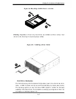
Страница 81: ...very carefully The following measures are generally sufficient to protect your equipment from ESD damage Precautions Use a grounded wrist strap designed to prevent static discharge Touch a grounded m...

Страница 82: ...y the connection Connect the cable from JF1 on the serverboard to the Control Panel PCB printed circuit board Make sure the red wire plugs into pin 1 on both connectors Pull all excess cabling out of...

Страница 83: ...erform various main tenance tasks 1 Press the release tabs to remove the cover from the locked position Press both tabs at the same time 2 Once the top cover is released from the locked position slide...

Страница 84: ...which of the fans has failed Replacing System Fans Removing a Fan 1 Remove the top chassis cover while the system is still running to determine which of the fans has failed 2 Depress the tab on the si...

Страница 85: ...or remove power to replace or swap SATA drives Proceed to the next step for instructions Note You must use standard 1 high drives in the SuperServer 6047R E1R24N DVD ROM Floppy Disk Drive For install...

Страница 86: ...he drive s LEDs 2 Swing the handle fully out and use it to pull the drive carrier straight out Installing a Hard Drive to the Hard Drive Tray 1 Remove the two screws securing the dummy drive to the dr...

Страница 87: ...e 6 5 Installing a Drive Carrier Hard Drive Backplane The hard drives plug into a backplane that provides power drive ID and bus termi nation A RAID controller can be used with the backplane to provid...

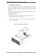
Страница 88: ...place when the system is operating please follow this procedure Air shrouds concentrate airflow to maximize fan efficiency The SC846 chassis air shroud does not require screws to set up Installing th...

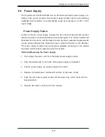
Страница 89: ...main on until the failed module has been replaced Replacements can be ordered directly from Supermicro see contact information in the Preface The power supply modules have a hot swap capability meanin...

Страница 90: ...b 6 7 Attaching a JBOD Expansion Chassis The SSG 6047R E1R24N features dual JBOD expansion ports The Figure below illustrates the recommended expansion strategy JBOD attachment will vary de pending on...

Страница 91: ...Chapter 6 Advanced Chassis Setup 6 11 Figure 6 8 JBOD Expansion Port 2x JBOD OUT downstream ports JBOD OUT downstream port JBOD OUT downstream port JBOD IN upstream port JBOD IN upstream port...

Страница 92: ...6 12 SUPERSTORAGESYSTEM 6047R E1R24N User s Manual Notes...
Страница 93: ...user The right frame displays the key legend Above the key legend is an area reserved for a text message When an option is selected in the left frame it is highlighted in white Often a text message w...

Страница 94: ...e wrong BIOS can cause irreparable damage to the sys tem In no event shall the manufacturer be liable for direct indirect special incidental or consequential damage arising from a BIOS update If you h...

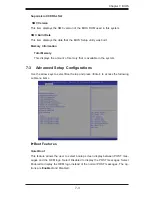
Страница 95: ...unt of memory that is available in the system 7 3 Advanced Setup Configurations Use the arrow keys to select Boot Setup and press Enter to access the following submenu items Boot Features Quiet Boot T...

Страница 96: ...is set to Disabled the ROM BIOS of the host adap tors will not capture Interrupt 19 and the drives attached to these adaptors will not function as bootable devices The options are Enabled and Disable...

Страница 97: ...in Socket 0 Type of CPU CPU Signature Microcode Patch CPU Stepping Maximum CPU Speed Minimum CPU Speed Processor Cores Intel HT Hyper Threading Technology Intel VT x Technology Intel SMX Technology L1...

Страница 98: ...allow the processor to designate areas in the system memory where an application code can execute and where it cannot thus preventing a worm or a virus from flooding illegal codes to overwhelm the pro...

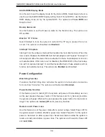
Страница 99: ...ect Disabled to disable power saving settings The options are Disabled Energy Efficiency and Custom EIST EIST Enhanced Intel SpeedStep Technology allows the system to automatically adjust processor vo...

Страница 100: ...e options are Enabled and Disabled Package C State limit This feature allows the user to set the limit on the C State package register The options are C0 C2 C6 and No Limit Factory Long Duration Power...

Страница 101: ...ements freeing the system resource for other tasks The options are Disabled and Enabled DCA Support Select Enabled to use Intel s DCA Direct Cache Access Technology to improve data transfer efficiency...

Страница 102: ...onent transmitter The options are P0 6 0 0 0 dB P1 3 5 0 0 dB P2 4 5 0 0 dB P3 2 5 0 0 dB P4 0 0 0 0 dB P5 0 0 2 0 dB P6 0 0 2 5 dB P7 6 0 3 5 dB P8 3 5 3 5 dB P9 0 0 3 5 dB and Auto IOU2 PCIe Port If...

Страница 103: ...set This feature allows the user to select the preset setting for a downstream compo nent transmitter The options are P0 6 0 0 0 dB P1 3 5 0 0 dB P2 4 5 0 0 dB P3 2 5 0 0 dB P4 0 0 0 0 dB P5 0 0 2 0 d...

Страница 104: ...et the QPI power state to a lower setting for QPI Link0s The options are Disabled and Enabled QPI Link0p This feature allows the user to set the QPI power state to a lower setting for QPI Link0p The o...

Страница 105: ...Auto 1 Way 2 Way 4 Way and 8 Way Patrol Scrub Patrol Scrubbing is a process that allows the CPU to correct correctable memory errors detected on a memory module and send the correction to the requesto...

Страница 106: ...This feature allows the user to select the serial message debug level The options are Minimum Maximum Trace and Memory Training South Bridge Configuration This feature allows the user to configure th...

Страница 107: ...abled EHCI ownership change will be claimed by the EHCI driver The options are Disabled and Enabled SATA Configuration When this submenu is selected the AMI BIOS automatically detects the presence of...

Страница 108: ...Disabled RAID Mode The following items are displayed when RAID Mode is selected PCH RAID CodeBase Select Intel or LSI to specify the code base to be used for RAID support The options are Intel and LS...

Страница 109: ...read the CPU temperature The options are Enabled and Disabled Alert Enable Lock Select Enabled to lock all alert enabling settings The options are Enabled and Disabled PCIe PCI PnP Configuration PCI R...

Страница 110: ...L0 to force all PCI E links to operate at L0 state Select Auto to allow the system BIOS to automatically set the ASPM level for the system Select Disabled to disable ASPM support The options are Disab...

Страница 111: ...re En abled and Disabled Device Settings This feature indicated if reset is required or not for a serial port specified Change Settings Use this feature to set the optimal Environment_Control_Interfac...

Страница 112: ...the data transmission size for Console Redirection The options are 7 Bits and 8 Bits Parity A parity bit can be sent along with regular data bits to detect data transmission errors Select Even if the...

Страница 113: ...ttings to support Out of Band Serial Port management ACPI Configuration Use this feature to configure Advanced Configuration and Power Interface ACPI power management settings for your system High Pre...

Страница 114: ...d TPM Owner Status This item displays the status of TPM Ownership Intel TXT LT SX Configuration Intel TXT LT SX Hardware Support This feature indicates if the following hardware components support the...

Страница 115: ...settings ME BIOS Interface Version ME Version iSCSI This item displays the following iSCSI information iSCSI Initiation Name This item displays the name of the iSCSI Initiator which is a unique name...

Страница 116: ...rror event logging for PCI slots The options are En abled and Disabled Erasing Settings Erase Event Log Select Enabled to erase the SMBIOS System Management BIOS Event Log which is completed before a...

Страница 117: ...o 99 The default setting is 60 View SMBIOS Event Log This item allows the user to view the event in the SMBIOS event log Select this item and press Enter to view the status of an event in the log Date...

Страница 118: ...mware installed in your system System Event Log Enabling Disabling Options SEL Components Select Enabled for all system event logging at bootup The options are Enabled and Disabled Erasing Settings Er...

Страница 119: ...to Yes the user is allow to configure the IPMI settings at next system boot Configuration Address Source This feature allows the user to select the source of the IP address for this com puter If Stati...

Страница 120: ...hell and Disabled Boot Option 2 This item allows the user to select the first boot device Select a LAN device to boot the system from the network connection Select UEFI to boot the system from the UEF...

Страница 121: ...the Administrator Password which is required to enter the BIOS setup utility The length of the password should be from 3 character long to 8 character long User Password Use this feature to set a User...

Страница 122: ...Save Changes and Reset When you have completed the system configuration changes select this option to save the changes and reboot the computer so that the new system configuration settings can take ef...

Страница 123: ...lts Select this feature and press Enter to save the current settings as the user s defaults When the dialog box appears asking you if you want to save values as user s defaults click Yes to save the c...

Страница 124: ...7 32 SUPERSTORAGESYSTEM 6047R E1R24N User s Manual Notes...
Страница 125: ...curs you should consult with your system manufacturer for possible repairs These fatal errors are usually communicated through a series of audible beeps The numbers on the fatal error list correspond...

Страница 126: ...A 2 SUPERSTORAGESYSTEM 6047R E1R24N User s Manual Notes...

Страница 127: ...68 GB of ECC registered RDRIMM Load Reduced LRDIMM or up to 128 GB of unbuffered UDIMM ECC non ECC DDR3 1600 1333 1066 800 4 channel memory modules 24 modules max for RDIMMs LRDIMMs 16 modules max for...

Страница 128: ...ud System Input Requirements AC Input Voltage 100 240V AC auto range Rated Input Current 13 4A max Rated Input Frequency 50 to 60 Hz Power Supply Rated Output Power 920W Part PWS 920P 1R Rated Output...

Страница 129: ...1000 4 4 EN 61000 4 5 EN 61000 4 6 EN 61000 4 8 EN 61000 4 11 Safety CSA EN IEC UL 60950 1 Compliant UL or CSA Listed USA and Canada CE Marking Europe California Best Management Practices Regulations...

Страница 130: ...to perform be reasonably expected to result in significant injury or loss of life or catastrophic property damage Accordingly Supermicro dis claims any and all liability and should buyer use or sell s...

Отзывы: