Chapter 5: Advanced Motherboard Setup
5-9
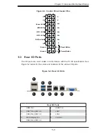
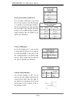
HDD LED
The HDD LED connection is located on
pins 13 and 14 of JF1. Attach a hard
drive LED cable here to display disk
activity (for any hard drive activities on
the system, including Serial ATA and
IDE). See the table on the right for pin
defi nitions.
HDD LED
Pin Defi nitions (JF1)
Pin# Defi nition
13
+3.3V
14
HD Active
Power LED
The Power LED connection is located on
pins 15 and 16 of JF1. Refer to the table
on the right for pin defi nitions.
Power LED
Pin Defi nitions (JF1)
Pin# Defi nition
15
+3.3V
16
Ground
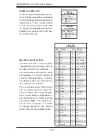
LAN Ports (LAN1/LAN2)
Two gigabit LAN ports are located on
the I/O back panel. These ports accept
RJ45 type cables. Refer to the table on
the right for pin defi nitions.
RJ45/LAN
Pin Defi nitions
Pin # Defi nition
Pin # Defi nition
1
TX_D1+
5
BI_D3-
2
TX_D1-
6
RX_D2-
3
RX_D2+
7
BI_D4+
4
BI_D3+
8
BI_D4-
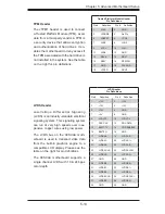
Fan Header
Pin Defi nitions
Pin# Defi nition
1
Ground
2
+12V
3
Tachometer
4
PWM_Control
Fan Headers
The X9SCAA has one fan header re-
served for the system (Fan1).
Содержание 1017A-MP
Страница 1: ... SUPERSERVER 1017A MP SUPER USER S MANUAL 1 0 ...
Страница 5: ...Notes Preface v ...
Страница 14: ...2 2 SUPERSERVER 1017A MP User s Manual Notes ...
Страница 16: ...SUPERSERVER 1017A MP User s Manual 3 2 Notes ...
Страница 36: ...4 20 SUPERSERVER 1017A MP User s Manual Notes ...
Страница 87: ...A 2 SUPERSERVER 1017A MP User s Manual Notes ...
Страница 90: ...B 3 Appendix B System Specifications Notes ...


