


2-26
X7DBX-8/X7DBX-i
User's
Manual
S
UPER X7DBX
LAN1
®
LAN2
Fan1/2
FP CTRL
I-SATA0-3
S M B
Battery
(North
Bridge)
VGA
COM1
USB0/1
JPG1
(South
Bridge)
P X H
DIMM 1A (Bank 1)
JPA1
Chan. A SCSI
I-SATA4
JPL2
SBX-E2 X4
PCI-X 100MHz ZCR
Slot7
DIMM 1B (Bank 1)
DIMM 2A (Bank 2)
DIMM 2B (Bank 2)
DIMM 3A (Bank 3)
DIMM 3B (Bank 3)
DIMM 4A (Bank 4)
DIMM 4B (Bank 4)
JBT1
JWOR
SPEC
DA2
JWOL
S I/O
LAN
CTRL
SIM1U IPMI
KB
Mouse
JPL1
PCI-X 133MHz
SBX-E1 X8
Chan.B SCSI
S C S I
CTRL
COM2
Floppy
I-SATA5
JI
2
C 1
JI
2
C 2
JPA2
JPA3
DA1
J7
JP1
JOH1
JWF2
JCF2
JWF1
JCF1
IDE#1
Compact Flash
JL1
9-Pin
PWR
20-Pin
P W R
BIOS
Buzzer
USB2/3
USB4
CPU1
CPU2
Fan3/4
Fan5/6
Fan7/8
Fan9/10
JWD
LE1
PCI-E x8/x4
VGA
CTRL
ESB2
5000P
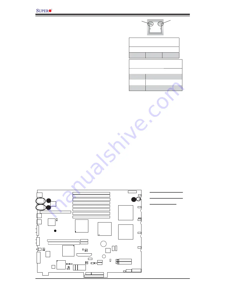
2-7 Onboard
Indicators
A
B
A. GLAN Port1 LEDs
B. GLAN Port2 LEDs
C. Standby LED
A c t i v i t y
LED
L i n k
LED
Onboard Power Standby LED
There is an Onboard Standby LED lo-
cated AT LE1 on the motherboard. See
the layout below for the LED location.
C
GLAN Link Indicator
LED Color Defi nition
Off
No Connection or 10 Mbps
Green
100 Mbps
Amber
1 Gbps
GLAN Activity Indicator
Color Status Defi nition
Amber
Flashing
Active
GLAN LEDs
There are two GLAN ports on the moth-
erboard. Each Gigabit Ethernet LAN port
has two LEDs. The green LED indicates
activity, while the power LED may be green,
amber or off to indicate the speed of the
connection. See the tables at right for more
information.
Содержание X7DBX-8
Страница 1: ... X7DBX 8 X7DBX i USER S MANUAL Revision 1 0 SUPER ...
Страница 20: ...1 14 X7DBX 8 X7DBX i User s Manual Notes ...
Страница 86: ...A 6 X7DBX 8 X7DBX i User s Manual Notes ...
Страница 92: ...B 6 X7DBX 8 X7DBX i User s Manual Notes ...
Страница 126: ...E 4 X7DBX 8 X7DBX i User s Manual Notes ...