58
Chapter 3: Maintenance and Component Installation
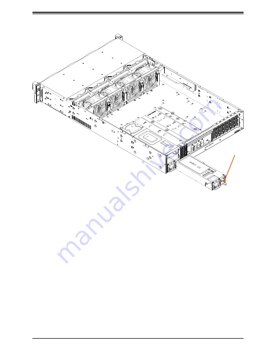
Figure 3-17. Replacing the Power Supply
Release Tab
Страница 1: ...USER S MANUAL Revision 1 0 SuperServer 620P ACR16H 620P ACR16L...
Страница 2: ...ss A device or in residential environment for Class B device This equipment generates uses and can radiate radio frequency energy and if not installed and used in accordance with the manufacturer s in...
Страница 3: ...ivers and utilities https www supermicro com wdl driver Product safety info http www supermicro com about policies safety_information cfm If you have any questions please contact our support team at s...
Страница 4: ...er Installation 2 1 Overview 20 2 2 Unpacking the System 20 2 3 Preparing for Setup 20 Choosing a Setup Location 20 Rack Precautions 21 Server Precautions 21 Rack Mounting Considerations 21 Ambient Op...
Страница 5: ...from the Carrier Assembly 41 3 4 Memory 42 Memory Support 42 Optane PMem Population 44 PMem Notes 44 Memory Population Guidelines 45 Guidelines Regarding Mixing DIMMs 45 DIMM Construction 45 Installin...
Страница 6: ...trictions 78 Supported SSDs and Operating Sytems 78 Additional Information 79 Hardware Key 79 Configuring NVMe RAID Manually 80 Status Indications 85 Hot Swap Drives 85 Hot unplug 85 Hot plug 85 Relat...
Страница 7: ...2 7 7 Where to Get Replacement Components 93 7 8 Reporting an Issue 93 Technical Support Procedures 93 Returning Merchandise for Service 93 Vendor Support Filing System 94 7 9 Feedback 94 7 10 Contact...
Страница 8: ...ddress Super Micro Computer B V Het Sterrenbeeld 28 5215 ML s Hertogenbosch The Netherlands Tel 31 0 73 6400390 Fax 31 0 73 6416525 Email sales supermicro nl General Information support supermicro nl...
Страница 9: ...ile Two PCIe 4 0 x8 low profile see Section 3 10 for details I O Ports LAN Two RJ45 10G BASE T one RJ45 dedicated BMC LAN port USB Four USB 3 0 ports Rear One VGA port Rear One COM port Rear Two Super...
Страница 10: ...tions some LED indications are not supported such as hot spare For VROC configurations refer to the VROC section in this manual Drive Carrier LED Indicators Color Blinking Pattern Behavior for Device...
Страница 11: ...when flashing Power Fail LED Indicates a power supply module has failed Information LED Alerts operator to several states as noted in the table below Information LED Color Status Description Red cont...
Страница 12: ...plies Two redundant power supply modules PWS1 on the bottom PWS2 on the top Drives Two optional 2 5 hot swap storage drives SATA or NVMe BMC Dedicated LAN port for BMC for indicator details see BMC LA...
Страница 13: ...AC cord unplugged and in redundant mode OR power supply critical events causing a shutdown failure OCP OVP fan fail OTP UVP Amber blinking Power supply warning events where the power supply continues...
Страница 14: ...e This section shows the locations of the system electronic components Figure 1 4 Main Component Locations Storage Backplane BPN SAS3 LA26 N12 Motherboard X12DPi N T 6 Drive Bays Storage Backplane BPN...
Страница 15: ...dules DIMM Slots 16 DIMM memory slots Processors 3rd Gen Intel Xeon Scalable with heatsinks Drive Bays Four 3 5 hot swap top loading drive bays System Fans Four 8 cm fans with Optimal Fan Speed Contro...
Страница 16: ...MF1 P2 DIMMH1 CPU2 CPU1 CPU1 SLOT1 PCIe 4 0 X8 CPU1 SLOT2 PCIe 4 0 X16 CPU1 SLOT3 PCIe 4 0 X16 CPU2 SLOT4 PCIe 4 0 X16 CPU2 SLOT5 PCIe 4 0 X16 CPU2 SLOT6 PCIe 4 0 X8 P1 DIMMB1 P1 DIMMA1 P1 DIMMD1 P1 D...
Страница 17: ...face connector see Note below JNVI2 C NVMe I2 C header JPI2 C1 Power System Management Bus SMB I2 C header JPWR2 JPWR4 8 pin power connectors JPWR3 24 pin ATX power connector JSTBY1 Standby power head...
Страница 18: ...header with support for two USB 2 0 ports USB2 3 USB7 8 3 0 Rear I O USB 3 0 ports USB4 5 3 0 Front accessible USB header with support for two USB 3 0 ports USB6 Internal Type A USB 3 0 port UID LED...
Страница 19: ...SLOT 6 PECI 31 12 1 LAN3 To CMM W83773G 2 RT1 RT2 2666 2933 3200 2666 2933 3200 PCIe X16 DDR4 CPU2 C1 BMC PCIe X8 G4 CPU2 F1 SPI CPU1 CPU2 A1 UPI SPI 2666 2933 3200 PCIe GEN4 X16 0 5 PCIe X16 G4 CPU2...
Страница 20: ...be situated in a clean dust free area that is well ventilated Avoid areas where heat electrical noise and electromagnetic fields are generated It will also require a grounded AC power outlet nearby Be...
Страница 21: ...the electrical and general safety precautions in Appendix A Determine the placement of each component in the rack before you install the rails Install the heaviest server components at the bottom of t...
Страница 22: ...be maintained at all times To ensure this the rack itself should be grounded Particular attention should be given to power supply connections other than the direct connections to the branch circuit i...
Страница 23: ...installation instructions that came with the specific rack you are using Identifying the Rails The chassis package includes two rail assemblies Each assembly consists of three sections An inner rail t...
Страница 24: ...tely out of the rack when when the chassis is pulled out for servicing To mount the rail onto the chassis first release the inner rail from the outer rails 1 Pull the inner rail out of the outer rail...
Страница 25: ...r rail firmly against the side of the chassis aligning the hooks on the side of the chassis with the holes in the inner rail 3 Slide the inner rail forward toward the front of the chassis until the qu...
Страница 26: ...il adjusting the length until it just fits within the posts of the rack 5 Hang the hooks of the rear section of the outer rail onto the square holes on the rear of the rack Take care that the proper h...
Страница 27: ...Align the inner rails of the chassis with the outer rails on the rack 3 Slide the inner rails into the outer rails keeping the pressure even on both sides When the chassis has been pushed completely...
Страница 28: ...Be sure to have sufficient assistance supporting the chassis when removing it from the rack Use a lift 1 If necessary loosen the thumb screws on the front of the chassis that hold it in the rack 2 Pu...
Страница 29: ...Removing Power Use the following procedure to ensure that power has been removed from the system This step is necessary when removing or installing non hot swap components or when replacing a non red...
Страница 30: ...inside of the server Removing the System Fan and Top Loading Drive Bay Cover 1 Power down the server as described in section 4 1 and remove the two screws from the sides of the chassis cover 2 Lift th...
Страница 31: ...3 Slide the rear top cover toward the rear of the chassis 4 Lift the rear top cover off the chassis Check that all ventilation openings on the top cover and the top of the chassis are clear and unobs...
Страница 32: ...hat the plastic protective cover is on the CPU socket and that none of the socket pins are bent If they are contact your retailer When handling the processor avoid touching or placing direct pressure...
Страница 33: ...down Locate the gold triangle at the corner of the processor and the corresponding hollowed triangle on the processor carrier as shown below These triangles indicate the location of pin 1 Latch Latch...
Страница 34: ...of the processor under latch 1 on the carrier and then press the other end down until it snaps into latch 2 and is properly seated on the carrier Processor Carrier Assembly Top View Processor Carrier...
Страница 35: ...derside of the heatsink 1 Turn the heatsink over with the thermal grease facing up Note the two triangle cutouts A B located at the diagonal corners of the heatsink as shown in the drawing below 2 On...
Страница 36: ...nd Component Installation Installing the PHM into the CPU Socket 1 Remove the plastic protective cover from the CPU socket Gently squeeze the grip tabs then pull the cover off CPU Socket with Plastic...
Страница 37: ...ting Wire 4 Threaded Fastener Heatsink CPU Socket Peek Nut Rotating Wire Side View Top View Unlatched State a b c d a b c d Threaded Fasteners CPU Socket Pin1 Threaded Fastener CPU Socket 2 Locate fou...
Страница 38: ...B C D on the heatsink with threaded fasteners b c d on the CPU socket 6 Gently place the heatsink on the CPU socket making sure that each nut is properly aligned with its corresponding threaded fasten...
Страница 39: ...CPU Socket Be sure the system is shut down and all AC power cords are unplugged 1 Use a t30 bit screwdriver to loosen the four PEEK nuts on the heatsink in the sequence of A B C and D A B C D Peek Nut...
Страница 40: ...or Carrier Assembly from the PHM Detach the four plastic clips a b c d on the processor carrier assembly from the four corners of the heatsink A B C D as shown below and lift off the processor carrier...
Страница 41: ...the Carrier Assembly Unlock the lever from its locked position and push it upwards to disengage the processor from the carrier as shown below right Carefully remove the processor from the carrier Proc...
Страница 42: ...Product Resources page DDR4 Memory Support for 3rd Gen Intel Xeon Scalable Processors Type Ranks Per DIMM and Data Width DIMM Capacity GB Speed MT s DRAM Density One DIMM per Channel Two DIMMs per Ch...
Страница 43: ...MMs A1 B1 C1 D1 E1 F1 G1 H1 and PMem in B2 2 CPUs 2 DIMMs CPU1 A1 CPU2 A1 2 CPUs 4 DIMMs CPU1 A1 E1 CPU2 A1 E1 2 CPUs 6 DIMMs CPU1 A1 C1 E1 G1 CPU2 A1 E1 2 CPUs 8 DIMMs CPU1 A1 C1 E1 G1 CPU2 A1 C1 E1...
Страница 44: ...MM Memory Mode Validation Matrix DDR4 DIMMs Validated with PMem 200 Series DIMM Type up to 3200 Ranks Per DIMM Data Width Stack DIMM Capacity GB DRAM Density 8Gb 16Gb RDIMM 1Rx8 N A N A 1Rx4 16GB 32G...
Страница 45: ...Regarding Mixing DIMMs Populating slots with a pair of DIMM modules of the same type and size results in inter leaved memory which improves memory performance Use memory modules of the same type and s...
Страница 46: ...power from the system as described in Section 3 1 Follow the memory population sequence in the table above 1 Push the release tabs outwards on both ends of the DIMM slot to unlock it Notches Release T...
Страница 47: ...the motherboard Replacing the Battery Begin by removing power from the system 1 Push aside the small clamp that covers the edge of the battery When the battery is released lift it out of the holder 2...
Страница 48: ...age drives use the X12DPi N T 6 motherboard page The drives are mounted in toolless drive carriers that simplify their removal from the chassis These carriers also help promote proper airflow Note Ent...
Страница 49: ...Drive in a Drive Carrier 1 To add a new drive install it into the carrier with the printed circuit board side facing down so that the mounting holes align with those in the carrier 2 Secure the drive...
Страница 50: ...lace the carrier back into the drive bay Hard Drive Carrier Indicators Each hard drive carrier has two LED indicators an activity indicator and a status indicator In RAID configurations the status ind...
Страница 51: ...oving or installing the hard drives from their individual trays Setting up the Internal Chassis Tray and Individual Trays 1 Power down the system and remove the chassis covers as described in Section...
Страница 52: ...er from the Hard Drive Tray Figure 3 12 Installing a Hard Drive into its Tray 5 Lift the individual trays up and out of the chassis tray 6 Place a hard drive into each of the individual trays and secu...
Страница 53: ...ard Drives and Carriers into the Hard Drive Tray Figure 3 14 Installing the Hard Drive Tray into the Chassis 9 Place the loaded chassis tray into the chassis 10 Secure the chassis tray with the two si...
Страница 54: ...have been installed as directed in the previous section 2 With the power running remove the middle top cover as described in Section 3 2 3 Lift the latch on the individual tray and slide the hard driv...
Страница 55: ...is controlled by system temperature using the BMC If a fan fails the remaining fans will ramp up to full speed and the system will continue to operate Replace any failed fan at your earliest convenien...
Страница 56: ...ir shrouds concentrate airflow to maximize fan efficiency They do not require screws to install Installing the Standard Air Shroud Position the air shroud as illustrated in the figure below sliding th...
Страница 57: ...LED displays the status Solid Green When illuminated indicates that the power supply is on Blinking Green When blinking indicates that the power supply is plugged in and turned off by the system Blin...
Страница 58: ...58 Chapter 3 Maintenance and Component Installation Figure 3 17 Replacing the Power Supply Release Tab...
Страница 59: ...chassis slot cover 3 Insert the expansion card into a slot on the motherboard while aligning the expansion card backplate with the open slot in the rear of the chassis Secure with a screw 4 Replace th...
Страница 60: ...to this section when routing or rerouting cables Proper routing is important to maintain airflow through the system Cable part numbers and descriptions are available at the Online Cable Matrix Backpl...
Страница 61: ...LAN port 4 and two 10G BASE T ports 7 and 8 Unit Identifier Switch UID LED Indicator A Unit Identifier UID switch 10 and a UID LED indicator are located on the rear of the system When you press the U...
Страница 62: ...ion 1 4 Ground 5 8 12 Vdc 4 pin Power Pin Definitions Pin Definition 1 2 Ground 3 4 12Vdc 4 3 Headers and Connectors Fan Headers There are seven fan headers FAN1 FAN5 FANA FANB on the motherboard Thes...
Страница 63: ...Header Pin Definitions Pin Definition Pin Definition 1 P3V3 2 SPI_TPM_CS_N 3 PCI E_RESET_N 4 SPI_PCH_MISO 5 SPI_PCH_CLK 6 Ground 7 SPI_PCH_MOSI 8 N A 9 JTPM1_P3V3A 10 IRQ_TPM_SPIN_N Disk On Module Pow...
Страница 64: ...ct the appropriate cable here to use the IPMB I2 C connection on your system External I2 C Header Pin Definitions Pin Definition 1 Data 2 Ground 3 Clock 4 3V3_STBY NVMe I2 C Header Connector JNVI2 C1...
Страница 65: ...Baseboard Management Controller BMC and a Network Interface Controller NIC Use a NIC add on card that supports NC SI and a special cable Please contact Supermicro at www supermicro com to purchase th...
Страница 66: ...locations and definitions of the control panel buttons and LED indicators All JF1 wires have been bundled into a single cable to simplify this connection Make sure the red wire plugs into pin 1 as ma...
Страница 67: ...On Overheat Flashing Fan Fail Overheat OH Fan Fail Connect an LED cable to pins 7 and 8 of JF1 to use the Overheat Fan Fail LED connections The LED on pin 8 provides warnings of overheat or fan failu...
Страница 68: ...o pin 13 to use UID switch HDD LED Pin Definitions JF1 Pin Definition 13 3 3V Standby UID Switch 14 HDD Active Power LED The Power LED connection is located on pins 15 and 16 of JF1 Power LED Pin Defi...
Страница 69: ...e the motherboard layout page for jumper locations Note On a two pin jumper Closed means the jumper is on both pins and Open indicates the jumper is either on only one pin or has been completely remov...
Страница 70: ...beat indicator When the LED is blinking green BMC is functioning normally 4 5 LED Indicators Network LAN LEDs The Ethernet ports each have two LEDs One LED indicates activity when flashing green The o...
Страница 71: ...dows OS and the RAID driver Refer to the RAID Configuration User Guides posted on our website at www supermicro com support manuals Installing the OS 1 Create a method to access the MS Windows install...
Страница 72: ...iver browse the USB flash drive for the proper driver files For RAID choose the SATA sSATA RAID driver indicated then choose the storage drive on which you want to install it For non RAID choose the S...
Страница 73: ...Another option is to go to the Supermicro website at www supermicro com Products Find the product page for your motherboard and Download the Latest Drivers and Utilities Insert the flash drive or disk...
Страница 74: ...Network Management Protocol SNMP SuperDoctor 5 comes in local and remote management versions and can be used with Nagios to maximize your system monitoring needs With SuperDoctor 5 Management Server...
Страница 75: ...related to BMC For general documentation and information on BMC visit our website at www supermicro com en solutions management software bmc resources BMC ADMIN User Password For security each system...
Страница 76: ...Control Card and Cable s TPM security module Intel VROC RAID Key 6 1 Additional Storage Drives The system supports two hot swap 2 5 SATA or NVMe drives accessible from the chassis rear 6 2 Storage Con...
Страница 77: ...d to connect a Trusted Platform Module TPM A TPM is a security device that supports encryption and authentication in hard drives It enables the motherboard to deny access if the TPM associated with th...
Страница 78: ...Storage Technology enterprise Intel RSTe Driver for Linux Windows https downloadcenter intel com download 28108 Intel Virtual RAID on CPU Intel VROC and Intel Rapid Storage Technology enterprise Intel...
Страница 79: ...he key options are Intel VROC Keys VROC Package Description Part Number Intel MM Number Standard RAID 0 1 10 Supports 3rd party SSDs AOC VROCSTNMOD 951605 Premium RAID 0 1 5 10 Supports 3rd party SSDs...
Страница 80: ...s 2 Switch to Advanced Chipset Configuration North Bridge IIO Configuration Intel VMD Technology Figure 6 2 BIOS Selecting VMD Mode You can select a mode The default is Auto The VMD switch enables VMD...
Страница 81: ...ptional Components Figure 6 3 BIOS Manual Mode Example your server may look different 3 Select the desired PStack to Enable or Disable the corresponding Intel VMD controller Figure 6 4 BIOS Enabling V...
Страница 82: ...Capability can also be Enabled or Disabled Figure 6 5 BIOS Enabling VMD Functionality per Slot 5 Repeat steps 3 and 4 for each PStack on each CPU to be enabled or disabled In this example we enabled C...
Страница 83: ...ume associated with the VMD controller before disabling the controller Failure to do so may lead to unexpected behavior Note The effects of physically changing or swapping a CPU on the VMD controller...
Страница 84: ...disks RAID1 Select only two disks RAID5 Select at least three 3 24 disks RAID10 Select only four disks 12 Select Stripe Size Default 64KB 13 Select Create Volume 14 If another RAID is needed start ag...
Страница 85: ...evice Hot plug Physically install the device ESXi will automatically discover NVMe SSDs but a manual scan may be required in some cases Related Information Links 1 https kb vmware com s article 215140...
Страница 86: ...y and other service extensions Direct Links for the 620P ACR16 H L System Web 620P ACR16H and 620P ACR16L specifications page X12DPi N T 6 motherboard page for links to the Quick Reference Guide User...
Страница 87: ...BMC For general documentation and information on BMC please visit our website at https www supermicro com en solutions management software bmc resources Figure 7 2 BMC Sample For validated memory use...
Страница 88: ...ll the battery upside down 8 Verify that all jumpers are set to their default positions 9 Check that the power supplies input voltage operate at 100 120v or 180 240v 10 Turn the power switch on and of...
Страница 89: ...ction 3 3 for memory details 3 Check for bad DIMM modules or slots by swapping modules between slots and noting the results 4 Check the power supply voltage 115V 230V switch Losing the System Setup Co...
Страница 90: ...of installation Make sure that the devices used for installation are working properly including boot devices such as CD 2 Cable connection Check to make sure that all cables are connected and working...
Страница 91: ...to provide information to support staff You can download a crash dump of status information using BMC Check the BMC Error Log 1 Access the BMC web interface 2 Click the Server Health tab then Event L...
Страница 92: ...e system Notes Clearing CMOS will also clear all passwords Do not use the PW_ON connector to clear CMOS JBT1 contact pads 7 6 BMC Reset The BMC can be reset using the UID button Reset Press and hold t...
Страница 93: ...boot block code 3 If you still cannot resolve the problem include the following information when contacting us for technical support System motherboard and chassis model numbers and PCB revision numbe...
Страница 94: ...lure due to the alteration misuse abuse or improper maintenance of products During the warranty period contact your distributor first for any product problems Vendor Support Filing System For issues r...
Страница 95: ...om Europe Address Super Micro Computer B V Het Sterrenbeeld 28 5215 ML s Hertogenbosch The Netherlands Tel 31 0 73 6400390 Fax 31 0 73 6416525 Email sales supermicro nl General Information support sup...
Страница 96: ...sistance Only certified technicians should attempt to install or configure components Read this appendix in its entirety before installing or configuring components in the Supermicro chassis These war...
Страница 97: ...idere los riesgos de la corriente el ctrica y familiar cese con los procedimientos est ndar de prevenci n de accidentes Al final de cada advertencia encontrar el n mero que le ayudar a encontrar el te...
Страница 98: ...ient u zich bewust te zijn van de bij een elektrische installatie betrokken risico s en dient u op de hoogte te zijn van de standaard procedures om ongelukken te voorkomen Gebruik de nummers aan het e...
Страница 99: ...n Attention Avant de brancher le syst me sur la source d alimentation consulter les directives d installation Circuit Breaker Waarschuwing Raadpleeg de installatie instructies voordat u het systeem o...
Страница 100: ...del edificio Aseg rese de que el dispositivo de protecci n no sea superior a 250 V 20 A Attention Pour ce qui est de la protection contre les courts circuits surtension ce produit d pend de l installa...
Страница 101: ...g a y del cable el ctrico quitado de los m dulos de fuente de alimentaci n antes de tener acceso el interior del chasis para instalar o para quitar componentes de sistema Attention Le syst me doit tre...
Страница 102: ...chuwing Voordat u toegang neemt tot het binnenwerk van de behuizing voor het installeren of verwijderen van systeem onderdelen dient u alle spanningsbronnen en alle stroomkabels aangesloten op de voed...
Страница 103: ...lte nur geschultem qualifiziertem Personal gestattet werden Advertencia Solamente el personal calificado debe instalar reemplazar o utilizar este equipo Attention Il est vivement recommand de confier...
Страница 104: ...de estas reas mediante la utilizaci n de una herramienta especial cerradura con llave u otro medio de seguridad Attention Cet appareil doit tre install e dans des zones d acc s r serv s L acc s une z...
Страница 105: ...verkregen worden door gebruik te maken van speciaal gereedschap slot en sleutel of andere veiligheidsmaatregelen Battery Handling Warning There is the danger of explosion if the battery is replaced in...
Страница 106: ...eichen oder vom Hersteller empfohlenen Batterietyp Entsorgen Sie die benutzten Batterien nach den Anweisungen des Herstellers Attention Danger d explosion si la pile n est pas remplac e correctement N...
Страница 107: ...n dass der Einheit kein trom zugef hrt wird m ssen alle Verbindungen entfernt werden Advertencia Puede que esta unidad tenga m s de una conexi n para fuentes de alimentaci n Para cortar por completo e...
Страница 108: ...dous voltage or energy is present on the backplane when the system is operating Use caution when servicing Waarschuwing Deze eenheid kan meer dan n stroomtoevoeraansluiting bevatten Alle aansluitingen...
Страница 109: ...ng Wenn das System in Betrieb ist treten auf der R ckwandplatine gef hrliche Spannungen oder Energien auf Vorsicht bei der Wartung Advertencia Cuando el sistema est en funcionamiento el voltaje del pl...
Страница 110: ...Electrical Codes Warnung Die Installation der Ger te muss den Sicherheitsstandards entsprechen Advertencia La instalacion del equipo debe cumplir con las normas de electricidad locales y nacionales A...
Страница 111: ...regulations Advertencia Al deshacerse por completo de este producto debe seguir todas las leyes y reglamentos nacionales Attention La mise au rebut ou le recyclage de ce produit sont g n ralement sou...
Страница 112: ...chasis Mandtenga los dedos los destornilladores y todos los objetos lejos de las aberturas del ventilador Attention Pieces mobiles dangereuses Se tenir a l ecart des lames du ventilateur Il est possib...
Страница 113: ...al Safety Law prohibits the use of UL or CSA certified cables that have UL CSA shown on the cord for any other electrical devices than products designated by Supermicro only Waarschuwing Gevaarlijk be...
Страница 114: ...eln und oder Adapater die Ihre rtlichen Sicherheitsstandards einhalten Der Gebrauch von anderen Kabeln und Adapter k nnen Fehlfunktionen oder Feuer verursachen Die Richtlinien untersagen das Nutzen vo...
Страница 115: ...voldoen aan de lokale voorschriften en veiligheidsnormen inclusief de juiste kabeldikte en stekker Het gebruik van niet geschikte Kabels en of Adapters kan een storing of brand veroorzaken Wetgeving v...
Страница 116: ...uper DOMs disk on module ports PCI Expansion Slots Four PCIe 4 0 x16 low profile Two PCIe 4 0 x8 low profile see Section 3 10 for details Input Output LAN Two RJ45 10G BASE T one RJ45 dedicated BMC LA...
Страница 117: ...3 BS EN 61000 4 2 BS EN 61000 4 3 BS EN 61000 4 4 BS EN 61000 4 5 BS EN 61000 4 6 BS EN 61000 4 8 BS EN 61000 4 11 Product Safety 2014 35 EU LVD Directive UL CSA 62368 1 USA and Canada Electrical Equi...