


5-8
S
UPER
S
ERVER 5018D-MHR7N4P User's Manual
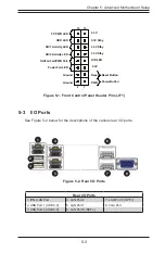
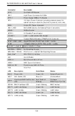
Connector
Description
JOH1
Overheat LED Header
JPH1
4-pin Power Connector for HDDs
JPI
2
C1
Power Supply SMBus I
2
C Header
JPV1
12V 8-pin Power Connector (provides alternate power for
special enclosure when the 24-pin ATX power is not in use)
JPW1
24-pin ATX Power Connector
JSD1, JSD2
SATA DOM (Device On Module) Power Connectors
JSMB1
SMBus Header
JSTBY1
5V Standby Power Header
JTGLED1
LAN7 ~ LAN8 Activity LED Header
JTPM1
Trusted Platform Module (TPM)/Port 80 Connector
LAN1, LAN2, LAN7,
LAN8
Gigabit Ethernet (RJ45) Ports (LAN1 ~ LAN2)
10Gigabit Ethernet (SFP+) Ports (LAN7 ~ LAN8)
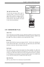
L-SAS0 ~ L-SAS15
SAS 2.0/SATA 3.0 Ports
M2-SRW1 ~ SRW3
M.2 Mounting Screws
MP-SRW1 ~ SRW2
PCI-E 2.0 x1 / I-SATA5 Slot Mounting Screws
Slot6, Slot7
CPU PCI-E 3.0 x8 Slot
UID
Unit ID Button
USB 0/1
Back Panel USB 3.0 Ports
USB 2
USB Type-A Connector
USB 3/4, 5/6
Front Access USB 2.0 Ports
VGA
VGA Port
LED
Description
Color/State
Status
LED3
Power LED
Green: On
System Power On
LED7
UID Switch LED
Blue: On
Unit Identified
LED8
Overheat/PWR Fail/Fan Fail
LED
Red: Solid on
Blinking
Overheat
PWR Fail or Fan Fail
LEDM1 BMC Heartbeat LED
Green: Blinking
BMC: Normal
LEDT1 LAN7 Link Status
Green: On
LAN7 Normal
LEDT2 LAN7 Activity
Green: Blinking
LAN7 Active
LEDT3 LAN8 Link Status
Green: On
LAN8 Normal
LEDT4 LAN8 Activity
Green: Blinking
LAN8 Active
Содержание SUPERSERVER 5018D-MHR7N4P
Страница 1: ...SUPERSERVER 5018D MHR7N4P USER S MANUAL 1 0 ...
Страница 5: ...Notes Preface v ...
Страница 14: ...1 6 SUPERSERVER 5018D MHR7N4P User s Manual Notes ...
Страница 116: ...7 40 SUPERSERVER 5018D MHR7N4P User s Manual Notes ...
Страница 118: ...A 2 SUPERSERVER 5018D MHR7N4P User s Manual Notes ...
Страница 121: ...B 3 Appendix B System Specifications Notes ...