Supermicro SUPERSERVER 1025TC-10G Скачать руководство пользователя страница 39

Chapter 5: Advanced Serverboard Setup

5-5

5-5  Processor and Heatsink Installation

IMPORTANT!

 Always connect the power cord last and remove it fi rst before add-

ing, removing or changing any hardware components. Make sure that you install 

the processor into the CPU socket 

before

 you install the heatsink and fan. The 

X7DCT/X7DCT-10G can support either one or two processors. If installing one 

processor only, install it into the CPU1 socket.

Notes:

Intel's boxed Xeon CPU package contains a CPU fan and heatsink assembly. 

If you buy a CPU separately, make sure that you use only Intel-certifi ed multi-

directional heatsinks and fans.

When purchasing a Xeon CPU or when receiving a serverboard with a CPU 

pre-installed, make sure that the CPU plastic cap is in place and none of the 

CPU pins are bent; otherwise, contact the retailer immediately.

1.

2.

!

When handling the processor, avoid placing direct pressure on the label 

area of the fan. Also, do not place the serverboard on a conductive 

surface, which can damage the BIOS battery and prevent the system 

from booting up.

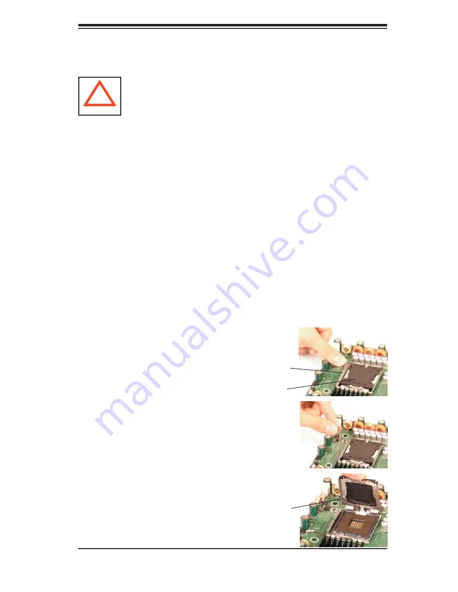
Installing the Processor 

1. A black PnP cap is attached to the 

load plate to protect the CPU socket.  

Press the load lever down and away 

from the retention clasp to release the 

load plate from its locked position.

 Load lever

2. Gently lift the load lever to open the 

load plate.

PnP cap

Load plate released

Содержание SUPERSERVER 1025TC-10G

Страница 1: ...SUPER SUPERSERVER 1025TC T SUPERSERVER 1025TC 10G USER S MANUAL Revision 1 0...

Страница 2: ...ERMICRO SHALL NOT HAVE LIABILITY FOR ANY HARDWARE SOFTWARE OR DATA STORED OR USED WITH THE PRODUCT INCLUDING THE COSTS OF REPAIRING REPLACING INTEGRATING INSTALLING OR RECOVERING SUCH HARDWARE SOFTWAR...

Страница 3: ...Introduction The rst chapter provides a checklist of the main components included with the server system and describes the main features of the Super X7DCT X7DCT 10G serverboard and the SC809T 780B ch...

Страница 4: ...mpers Refer to this chapter when adding or removing processors or main memory and when recon guring the serverboard Chapter 6 Advanced Chassis Setup Refer to Chapter 6 for detailed information on the...

Страница 5: ...v Preface Notes...

Страница 6: ...l Panel 1 5 Rear I O Panel 1 5 Cooling System 1 5 1 4 1U Twin System Notes 1 6 System Power 1 6 SATA Backplane Drives 1 6 1 5 Contacting Supermicro 1 7 Chapter 2 Server Installation 2 1 Overview 2 1 2...

Страница 7: ...LEDs 3 3 Chapter 4 System Safety 4 1 Electrical Safety Precautions 4 1 4 2 General Safety Precautions 4 2 4 3 ESD Precautions 4 3 4 4 Operating Precautions 4 4 Chapter 5 Advanced Serverboard Setup 5...

Страница 8: ...c Sensitive Devices 6 1 Precautions 6 1 Unpacking 6 1 6 2 Control Panel 6 2 6 3 System Fans 6 3 System Fan Failure 6 3 6 4 Air Shrouds 6 4 6 5 Drive Bay Installation Removal 6 5 Accessing the Drive Ba...

Страница 9: ...mponents may have been included with the 1025TC T 1025TC 10G as listed below Four 4 CPU heatsinks SNK P0017 SATA Accessories Eight 8 SATA hard drive carriers MCP 220 00001 03 Two 2 internal SATA backp...

Страница 10: ...s All memory modules used to populate the system should be the same size type and speed Serial ATA The South Bridge ICH9R of the chipset includes a Serial ATA controller for six Gb s SATA drives The h...

Страница 11: ...one set for each serverboard ATI Graphics Controller The X7DCT X7DCT 10G features an integrated ATI video controller based on the ES1000 graphics chip which includes 32 MB of DDR2 memory The ES1000 w...

Страница 12: ...apter 5 for details USB 2 0 3 0 Gb S Intel 5100 MCH PROCESSOR 2 ICH9R PCI EXP x8 GILGAL GB LAN FWH RJ45 RJ45 LPC SIO W83627GF ATI PCI 33MHz ES1000 VGA CONN KB MS PROCESSOR 1 1067 1333 MT S 1067 1333 M...

Страница 13: ...ch serverboard in the chassis Each control panel has LEDs to indicate power on net work activity hard disk drive activity and system overheat conditions Each control panel also includes a main power b...

Страница 14: ...s used for power supply monitoring are received by the primary serverboard only When viewed from the front of the chassis the serverboard on the left is referred to as the primary board and the server...

Страница 15: ...uper Micro Computer B V Het Sterrenbeeld 28 5215 ML s Hertogenbosch The Netherlands Tel 31 0 73 6400390 Fax 31 0 73 6416525 Email sales supermicro nl General Information support supermicro nl Technica...

Страница 16: ...1 8 SUPERSERVER 1025TC T 1025TC 10G User s Manual Notes...

Страница 17: ...age claim with the carrier who delivered it Decide on a suitable location for the rack unit that will hold the 1025TC T 1025TC 10G It should be situated in a clean dust free area that is well ventilat...

Страница 18: ...rack installation stabilizers should be attached to the rack In multiple rack installations the racks should be coupled together Always make sure the rack is stable before extending a component from t...

Страница 19: ...a ture Tmra Reduced Air ow Equipment should be mounted into a rack so that the amount of air ow required for safe operation is not compromised Mechanical Loading Equipment should be mounted into a rac...

Страница 20: ...the installation instructions that came with the rack unit you are using Note This rail will t a rack between 26 and 33 5 deep Identifying the Sections of the Rack Rails You should have received two...

Страница 21: ...hin the rack Installing the Inner Rail Extensions Figure 2 2 Place the inner rail extensions B over the preattached inner rails A which are attached to the side of the chassis Align the hooks of the i...

Страница 22: ...to the Front of the Rack Secure to the Rear of the Rack Figure 2 3 Assembling the Outer Rails Secure Outer Rails Together Installing the Server into a Rack Con rm that chassis includes the inner rails...

Страница 23: ...l First determine how far the server will extend out the front of the rack Larger chassis should be posi tioned to balance the weight between front and back If a bezel is included on your server remov...

Страница 24: ...e the system from the rack completely depress the locking tabs in the chassis rails push the right side tab down and the left side tab up to continue to pull the system out past the locked position Ch...

Страница 25: ...ves please refer to Chapter 6 Checking the Air ow Air ow is provided by six sets of 4 cm PWM fans each set of fans consists of two fans that are mounted back to back and an air shroud The system compo...

Страница 26: ...2 10 SUPERSERVER 1025TC T 1025TC 10G User s Manual Figure 2 5 Accessing the Inside of the System Remove these screws Remove this screw Remove this screw 1 2 3 1 4...

Страница 27: ...d to take Note that the server has two control panels one for each serverboard installed in the system This allows each serverboard to be controlled independently of the other 3 2 Control Panel Button...

Страница 28: ...heat condition which may be caused by cables obstructing the air ow in the system or the ambient room temperature being too warm Check the routing of the cables and make sure all fans are present and...

Страница 29: ...ystem is operating 3 4 SATA Drive Carrier LEDs Each SATA drive carrier has two LEDs Green When illuminated the green LED on the front of the SATA drive carrier indicates drive activity A connection to...

Страница 30: ...3 4 SUPERSERVER 1025TC T 1025TC 10G User s Manual Notes...

Страница 31: ...ting power you should rst power down the system with the operating system rst and then unplug the power cords of all the power supply units in the system When working around exposed electrical circuit...

Страница 32: ...jects from your body which are excellent metal conductors that can create short circuits and harm you if they come into contact with printed circuit boards or areas where power is present Serverboard...

Страница 33: ...static bags until ready for use Touch a grounded metal object before removing the board from the antistatic bag Do not let components or PCBs come into contact with your clothing which may retain a ch...

Страница 34: ...ure that the chassis cover is in place when the 1025TC T 1025TC 10G is operating to assure proper cooling Out of warranty damage to the system can occur if this practice is not strictly followed Figur...

Страница 35: ...to handle them very carefully see previous chapter To prevent the X7DCT X7DCT 10G serverboard from bending keep one hand under the center of the board to support it when handling The following measure...

Страница 36: ...ssis to gain full access to the inside of the server If already installed in a rack grasp the two handles on either side and pull the unit straight out until the rails lock into place See Figure 2 5 C...

Страница 37: ...the pin 1 locations The following data cables with their locations noted should be connected See the serverboard layout for connector locations Note that each connection listed should be made for bot...

Страница 38: ...cc Reset Button Power Button Ground x Key Power On LED HDD LED NIC1 LED NIC2 LED OH Fan Fail LED Power Fail LED Ground Ground 2 1 20 19 Connecting the Control Panel JF1 contains header pins for variou...

Страница 39: ...ti ed multi directional heatsinks and fans When purchasing a Xeon CPU or when receiving a serverboard with a CPU pre installed make sure that the CPU plastic cap is in place and none of the CPU pins a...

Страница 40: ...lly or vertically and do not rub the CPU against any sur face or any of the contacts which may damage the CPU and or contacts 7 With the CPU in the socket inspect the four corners of the CPU to make s...

Страница 41: ...3 Screw in two diagonal screws i e the 1 and the 2 screws until just snug Do not fully tighten the screws or you may damage the CPU 4 Add the two remaining screws then nish the installation by fully t...

Страница 42: ...into place in the slot see Figure 5 3 Repeat to install a total of four or six DIMMs if needed Note Due to allocating memory to system devices memory remaining available for operational use will be re...

Страница 43: ...System Memory Allocation Availability System Device Size Physical Memory Remaining Available 3 GB Total System Memory Physical Memory Remaining Available 4 GB Total System Memory Firmware Hub ash memo...

Страница 44: ...x16 cards Installing PCI Add on Cards Disconnect the power supply and open the chassis cover Pull open the add on card slot clip at the rear of the chassis Slide the temporary add on card L bracket to...

Страница 45: ...3 PCI Exp x16 SGPIO USB4 PWR_BKPlane PWR1 PWR2 COM SATA3 SATA2 SATA1 SATA0 DIMM3A DIMM3B DIMM1A DIMM1B DIMM2A DIMM2B SIMSO CPU1 LAN1 CPU2 LAN2 USB0 1 VGA Battery SPKR LAN CTRL Super I O FP CTLR LAN C...

Страница 46: ...2 Enabled JWD Watch Dog Pins 1 2 Reset Connector Description COM COM Serial Port FAN 1 3 System Fan Headers I2 C_PWR I2 C Power Connector JF1 Control Panel Header LAN1 2 Gigabit Ethernet RJ45 Ports J...

Страница 47: ...table on the right for the pin de nitions Only one of the two ATX power connectors from each serverboard should be connected to the power supply Reset Button Pin De nitions JF1 Pin De nition 3 Reset 4...

Страница 48: ...including Serial ATA and IDE See the table on the right for pin de nitions OH Fan Fail LED Pin De nitions JF1 Pin De nition 7 Vcc 8 Ground NIC1 LED Pin De nitions JF1 Pin De nition 11 Vcc 12 Ground NI...

Страница 49: ...ers See the table on the right for pin de nitions Note The onboard fan speed is con trolled by the CPU die temperature NMI Button The non maskable interrupt button header is located on pins 19 and 20...

Страница 50: ...s included on the serverboard This header is used to communicate with the System Monitor ing chip on the backplane to monitor SATA activity See the table on the right for pin de nitions SGPIO Header P...

Страница 51: ...so clear any passwords Instead of pins this jumper consists of contact pads to prevent accidentally clearing the contents of CMOS To Clear CMOS First power down the system and unplug the power cord s...

Страница 52: ...atch Dog Timer Watch Dog Jumper Settings JWD Jumper Setting De nition Pins 1 2 Reset Pins 2 3 NMI Open Disabled LAN1 LAN2 Enable Disable Change the setting of jumper JPL1 to enable or disable the LAN1...

Страница 53: ...Solid Power On System On Green ashing quickly ACPI S1 State Green ashing slowly ACPI S3 STR State Off Power Off power cable not connected Onboard Power LED LED3 There is an Onboard Power LED LE3 loca...

Страница 54: ...oot the system before proceeding with the next item on the list The bottom icon with a CD on it allows you to view the entire contents of the CD 5 12 Installing Additional Drivers After you ve install...

Страница 55: ...or III displays crucial system information such as CPU temperature system voltages and fan status See the Figure below for a display of the Supero Doctor III interface Notes The default User Name and...

Страница 56: ...e Revision 1 0 can be downloaded from our Web site at ftp ftp supermicro com utility Supero_Doctor_III You can also download SDIII User s Guide at http www supermicro com PRODUCT Manuals SDIII UserGui...

Страница 57: ...fully The following measures are generally suf cient to protect your equipment from ESD discharge Precautions Use a grounded wrist strap designed to prevent static discharge Touch a grounded metal obj...

Страница 58: ...connection Connect the cable from JF1 on the serverboard to the control panel PCB printed circuit board Make sure the red wire plugs into pin 1 on both connectors Pull all excess cabling out of the a...

Страница 59: ...m fans are hot swappable There is no need to power down the system when switching fans Changing a System Fan Figure 6 3 If necessary open the chassis while the power is running to determine which fan...

Страница 60: ...wo identical air shrouds are needed in the system one for each node Installing the Air Shrouds Figure 6 4 Con rm that all six fans are in place and working properly Place the rst air shroud into the c...

Страница 61: ...ed to the next step for instructions Note The operating system you use must have RAID support to enable the hot swap capability of the SATA drives Figure 6 4 Installing the Air Shrouds Use caution whe...

Страница 62: ...holes of both line up Note that there are holes in the carrier marked SATA to aid in correct installation Secure the drive to the carrier with four screws as illustrated below Insert the drive carrie...

Страница 63: ...will shut down and you will need to replace the power supply unit Replacement units can be ordered directly from Supermicro PWS 781 1S see contact information in Chapter 1 Replacing the Power Supply...

Страница 64: ...Release Tab Push the release tab on the back of the power supply as illustrated Pull the power supply out using the handle provided Push the new power supply module into the power bay until it clicks...

Страница 65: ...off a backup battery pro vides power to the CMOS Logic enabling it to retain system parameters Each time the computer is powered on the computer is con gured with the values stored in the CMOS Logic b...

Страница 66: ...s 1 By pressing Delete immediately after turning the system on or 2 When the message shown below appears briefly at the bottom of the screen during the POST Power On Self Test press the Delete key to...

Страница 67: ...ate Using the arrow keys highlight the month day and year elds and enter the correct data Press the Enter key to save the data BIOS Date This eld displays the date when this version of BIOS was built...

Страница 68: ...ect the type of IDE hard drive The option Auto will allow the BIOS to automatically con gure the parameters of the HDD installed at the connection Enter a number between 1 to 39 to select a predetermi...

Страница 69: ...Mode The options are Disabled Mode 0 Mode 1 Mode 2 Mode 3 Mode 4 and Mode 5 Serial ATA This setting allows the user to enable or disable the function of the Serial ATA The options are Disabled and En...

Страница 70: ...This display informs you how much system memory is recognized as being present in the system Extended Memory This display informs you how much extended memory is recognized as being pres ent in the sy...

Страница 71: ...display POST Error Messages if an error occurs during bootup If set to Disabled the system will continue to boot without displaying any error message even when a boot error occurs ACPI Mode Use the s...

Страница 72: ...tive for more than 5 minutes The options are Enabled and Disabled Summary Screen This setting allows you to Enable or Disable the summary screen which displays the system con guration during bootup Me...

Страница 73: ...tect to prevent data from being written into the base memory area of Block 512 640K Select Write Back to allow the CPU to write data back directly from the buffer without writing data to the System Me...

Страница 74: ...to make changes to the fol lowing Option ROM Scan When enabled this setting will initialize the device expansion ROM The options are Enabled and Disabled Enable Master This setting allows you to enabl...

Страница 75: ...cialized dedicated processor that is installed on an add on card or a network card to handle some or all packet processing of this add on card For this motherboard the TOE device is built inside the S...

Страница 76: ...source Memory is updated as well Select Enabled to use Demand Scrubbing for ECC memory correction Enable Multi Media Timer Select Yes to activate a set of timers that are alternative to the tradition...

Страница 77: ...d and Enabled Note For more information regarding hardware software support for this function please refer to Intel s and Microsoft s web sites Adjacent Cache Line Prefetch Available when supported by...

Страница 78: ...to use CPU Cache Line IP Prefetch The options are Disabled and Enabled Direct Cache Access Available when supported by the CPU Set to Enable to route inbound network IO traf c directly into processor...

Страница 79: ...to the following settings Event Log Validity This is a display to inform you of the event log validity It is not a setting Event Log Capacity This is a display to inform you of the event log capacity...

Страница 80: ...00 2400 9600 19 2K 38 4K 57 6K and 115 2K Console Type This item allows you to choose the console redirection type The options are VT100 VT100 8bit PC ANSI 7bit PC ANSI VT100 and VT UTF8 Flow Control...

Страница 81: ...pin if your chassis came with 3 pin fan headers Select 4 pin if your chas sis came with 4 pin fan headers Select Workstation if your system is used as a Workstation Select Server if your system is us...

Страница 82: ...Logging When this function is set to Disabled the system will continue to log events received via system interface The options are Enabled and Disabled Clear System Event Logging Enabling this functi...

Страница 83: ...nutes This feature allows the user to set the time value in minutes for the previous item OS Boot Watch Dog by keying in a desired number in the blank The default set ting is 10 minutes Please ignore...

Страница 84: ...ures fan speeds and voltages of various components 7 5 Security Choose Security from the Phoenix BIOS Setup Utility main menu with the arrow keys You should see the following display Security setting...

Страница 85: ...has not been used and Set means a user password has been entered for the system Set Supervisor Password When the item Set Supervisor Password is highlighted hit the Enter key When prompted type the Su...

Страница 86: ...t list section above are bootable devices listed in the sequence of boot order as speci ed The boot functions for the devices included in the candidate list above are currently disabled Use a key or a...

Страница 87: ...changes you made and to exit the BIOS Setup utility Exit Discarding Changes Highlight this item and hit Enter to exit the BIOS Setup utility without saving any changes you may have made Load Setup Def...

Страница 88: ...7 24 SUPERSERVER 1025TC T 1025TC 10G User s Manual Save Changes Highlight this item and hit Enter to save any changes you made You will remain in the Setup utility...

Страница 89: ...Keyboard controller failed test May require replacing keyboard controller Keyboard locked Unlock key switch Unlock the system to proceed Monitor type does not match CMOS Run SETUP Monitor type not co...

Страница 90: ...etup If the failure was caused by incorrect values and they are not corrected the next boot will likely fail On systems with control of wait states improper Setup settings can also terminate POST and...

Страница 91: ...est error Fail Safe Timer takes too long device Address Con ict Address con ict for speci ed device Allocation Error for device Run ISA or EISA Con guration Utility to resolve resource con ict for the...

Страница 92: ...tem not found Operating system cannot be located on either drive A or drive C Enter Setup and see if xed disk and drive A are properly identi ed Parity Check 1 nnnn Parity error found in the system bu...

Страница 93: ...devices have the Con guration Request bit set in the LCT Run an I2O Con guration Utility e g the SAC utility System BIOS shadowed System BIOS copied to shadow RAM UMB upper limit segment address nnnn...

Страница 94: ...A 6 SUPERSERVER 1025TC T 1025TC 10G User s Manual Notes...

Страница 95: ...tempt to initialize video and write the error in the top left corner of the screen The following is a list of codes that may be writ ten to port 80h POST Code Description 01h IPMI Initialization 02h V...

Страница 96: ...ager 36h Warm start shut down 38h Shadow system BIOS ROM 3Ah Auto size cache 3Ch Advanced con guration of chipset registers 3Dh Load alternate registers with CMOS values 41h Initialize extended memory...

Страница 97: ...and IRQs optional 81h Late POST device initialization 82h Detect and install external RS232 ports 83h Con gure non MCD IDE controllers 84h Detect and install external parallel ports 85h Initialize PC...

Страница 98: ...inate QuietBoot optional B6h Check password optional B7h Initialize ACPI BIOS and PPM Structures B9h Prepare Boot BAh Initialize SMBIOS BCh Clear parity checkers BDh Display MultiBoot menu BEh Clear s...

Страница 99: ...nterrupt vectors F1h Initialize Run Time Clock F2h Initialize video F3h Initialize System Management Manager F4h Output one beep F5h Clear Huge Segment F6h Boot to Mini DOS F7h Boot to Full DOS If the...

Страница 100: ...B 6 SUPERSERVER 1025TC T 1025TC 10G User s Manual Notes...

Страница 101: ...maximum up to 96 GB of registered ECC DDR2 667 533 SDRAM 48 GB per node Note interleaved memory requires DIMMs to be installed in pairs refer to Section 5 6 for details Serial ATA Controller Intel ICH...

Страница 102: ...781 1S Rated Output Voltages 12V 65A 180 240AC 58A 100 140AC 5Vsb 4A Operating Environment Operating Temperature 10 to 35 C 50 to 95 F Non operating Temperature 40 to 70 C 40 to 158 F Operating Relat...

Страница 103: ...lities or systems aircraft aircraft devices aircraft emergency com munication devices or other critical systems whose failure to perform be reasonably expected to result in signi cant injury or loss o...

Страница 104: ...C 4 SUPERSERVER 1025TC T 1025TC 10G User s Manual Notes...

Отзывы: