Supermicro SC101S Скачать руководство пользователя страница 31

3-1

Chapter 3: System Interface

Chapter 3  


System Interface

3-1  Power Switches

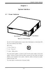
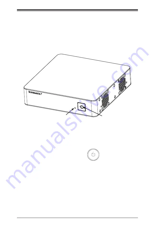
Figure 3-1. Power Buttons

Power Button

The SC101S front panel features a power button that displays a multicolored LED. 
The colors indicate server activity. 
LED colors:

• 

blue – Power on

• 

red – Power off

• 

white – HDD activity 

The power switch applies or removes power from the power supply to the server 
system. Turning off power with this button removes the main power but keeps 
standby power supplied to the system. Therefore, before servicing the system, 
unplug the power cord.
The reset button is located next to the power button.

Reset Button

Содержание SC101S

Страница 1: ...SC101S Chassis USER S MANUAL 1 0...

Страница 2: ...E OR DATA STORED OR USED WITH THE PRODUCT INCLUDING THE COSTS OF REPAIRING REPLACING INTEGRATING INSTALLING OR RECOVERING SUCH HARDWARE SOFTWARE OR DATA A n y disputes arising between manufacturer and...

Страница 3: ...technicians only This document lists compatible parts available when this document was published Refer to the Supermicor web site for updates on supported parts and configurations Warnings Special att...

Страница 4: ...Supermicro 1 4 Chapter 2 Standardized Warning Statements for AC Systems About Standardized Warning Statements 2 1 Warning Definition 2 1 Installation Instructions 2 4 Circuit Breaker 2 5 Power Disconn...

Страница 5: ...tenance 4 1 Overview 4 1 4 2 Removing the Power Cord 4 1 4 3 Removing the Chassis Cover 4 2 4 4 Installing Mounting Brackets 4 3 4 5 Installing the Hard Drive 4 4 4 6 Replacing the System Fan 4 5 Appe...

Страница 6: ...er B V Het Sterrenbeeld 28 5215 ML s Hertogenbosch The Netherlands Tel 31 0 73 6400390 Fax 31 0 73 6416525 Email sales supermicro nl General Information support supermicro nl Technical Support rma sup...

Страница 7: ...ar chassis model http www supermicro com Chapter 1 Introduction 1 1 Overview Supermicro s slim space saving SC101S Mini ITX Box chassis design 7 68 x 2 68 x 7 68 is a high performance solution ideal f...

Страница 8: ...tor User Interface The front control panel features a power on off button with LED illumination and a reset button Mounting The chassis is mountable with VESA or wall mount brackets 1 4 Where to get R...

Страница 9: ...must be mailed when service is complete For faster service RMA authorizations may be requested online http www supermicro com support rma Whenever possible repack the chassis in the original Supermicr...

Страница 10: ...Address Super Micro Computer B V Het Sterrenbeeld 28 5215 ML s Hertogenbosch The Netherlands Tel 31 0 73 6400390 Fax 31 0 73 6416525 Email sales supermicro nl General Information support supermicro n...

Страница 11: ...for assistance Only certified technicians should attempt to install or configure components Read this chapter in its entirety before installing or configuring components in the Supermicro chassis The...

Страница 12: ...e los riesgos de la corriente el ctrica y familiar cese con los procedimientos est ndar de prevenci n de accidentes Al final de cada advertencia encontrar el n mero que le ayudar a encontrar el texto...

Страница 13: ...l kan veroorzaken Voordat u aan enige apparatuur gaat werken dient u zich bewust te zijn van de bij een elektrische installatie betrokken risico s en dient u op de hoogte te zijn van de standaard proc...

Страница 14: ...s Systems an die Stromquelle die Installationsanweisungen lesen Advertencia Lea las instrucciones de instalaci n antes de conectar el sistema a la red de alimentaci n Attention Avant de brancher le sy...

Страница 15: ...ert ist Stellen Sie sicher dass der Nennwert der Schutzvorrichtung nicht mehr als 250 V 20 A betr gt Advertencia Este equipo utiliza el sistema de protecci n contra cortocircuitos o sobrecorrientes de...

Страница 16: ...Systemsbestandteile anzubringen oder zu entfernen Warning The system must be disconnected from all sources of power and the power cord removed from the power supply module s before accessing the chass...

Страница 17: ...nentes de sistema Attention Le syst me doit tre d branch de toutes les sources de puissance ainsi que de son cordon d alimentation secteur avant d acc der l int rieur du chassis pour installer ou enle...

Страница 18: ...s Installieren Ersetzen oder Bedienen dieser Ausr stung sollte nur geschultem qualifiziertem Personal gestattet werden Advertencia Solamente el personal calificado debe instalar reemplazar o utilizar...

Страница 19: ...stallation in Bereichen mit beschr nktem Zutritt vorgesehen Der Zutritt zu derartigen Bereichen ist nur mit einem Spezialwerkzeug Schloss und Schl ssel oder einer sonstigen Sicherheitsvorkehrung m gli...

Страница 20: ...ed by the manufacturer Dispose of used batteries according to the manufacturer s instructions Waarschuwing Dit apparaat is bedoeld voor installatie in gebieden met een beperkte toegang Toegang tot der...

Страница 21: ...ecommand e par le fabricant Jeter les piles usag es conform ment aux instructions du fabricant Advertencia Existe peligro de explosi n si la bater a se reemplaza de manera incorrecta Reemplazar la bat...

Страница 22: ...ra cortar por completo el suministro de energ a deben desconectarse todas las conexiones Attention Cette unit peut avoir plus d une connexion d alimentation Pour supprimer toute tension et tout couran...

Страница 23: ...ero es peligroso Tenga cuidado cuando lo revise Attention Lorsque le syst me est en fonctionnement des tensions lectriques circulent sur le fond de panier Prendre des pr cautions lors de la maintenanc...

Страница 24: ...l codes Warnung Die Installation der Ger te muss den Sicherheitsstandards entsprechen Advertencia La instalacion del equipo debe cumplir con las normas de electricidad locales y nacionales Backplane W...

Страница 25: ...ional laws and regulations Attention L quipement doit tre install conform ment aux normes lectriques nationales et locales Waarschuwing Bij installatie van de apparatuur moet worden voldaan aan de lok...

Страница 26: ...todas las leyes y reglamentos nacionales Attention La mise au rebut ou le recyclage de ce produit sont g n ralement soumis des lois et ou directives de respect de l environnement Renseignez vous aupr...

Страница 27: ...dedos los destornilladores y todos los objetos lejos de las aberturas del ventilador Attention Il est possible que les ventilateurs soient toujours en rotation lorsque vous retirerez le bloc ventilat...

Страница 28: ...ann zu einer Fehlfunktion oder ein Brand entstehen Elektrische Ger te und Material Safety Law verbietet die Verwendung von UL oder CSA zertifizierte Kabel UL oder CSA auf der Code f r alle anderen ele...

Страница 29: ...utres appareils lectriques que les produits d sign s par Supermicro seulement AC AC UL CSA UL CSA UL CSA Supermicro UL CSA AC Electrical Appliance and Material Safety Law UL CSA UL CSA Waarschuwing Bi...

Страница 30: ...2 20 SC101S Chassis Manual Notes...

Страница 31: ...ors indicate server activity LED colors blue Power on red Power off white HDD activity The power switch applies or removes power from the power supply to the server system Turning off power with this...

Страница 32: ...SC101S Chassis Manual 3 2 Notes...

Страница 33: ...assis These include information in Chapter 2 System Safety and the warning precautions listed in the setup instructions 4 2 Removing the Power Cord Before performing most setup or maintenance tasks us...

Страница 34: ...ese aside for later use 3 Slide the cover sideways as illlustrated above to release the front and rear cover hooks from the chassis 4 Lift the cover up and off the chassis Caution Except for short per...

Страница 35: ...tem as described in section 4 2 2 Choose the desired bracket mounting configuration from the two options below Configuration A Configuration B Figure 4 2 Mounting Bracket Configuration Options Figure...

Страница 36: ...er use Lift the tray out 3 Place the hard drive into the tray and secure it to the tray with the screws provided with hard drive 4 Return the hard drive tray assembly into the chassis aligning the tab...

Страница 37: ...over 2 Remove the failed fan power cable from motherboard 3 Remove the screws securing the fan to the chassis wall and set these aside for later use 4 Lift the fan out of the chassis 5 Align the repla...

Страница 38: ...SC101S Chassis Manual 4 6 Notes...

Страница 39: ...For more compatible cables refer to the manufacturer of the motherboard you are using and our Web site at www supermicro com Optional Cables Included with SC101S Chassis Part Type Length Description M...

Страница 40: ...reasonably expected to result in significant injury or loss of life or catastrophic property damage Accordingly Supermicro disclaims any and all liability and should buyer use or sell such products fo...

Отзывы: