


4-16
PDSMU User's Manual
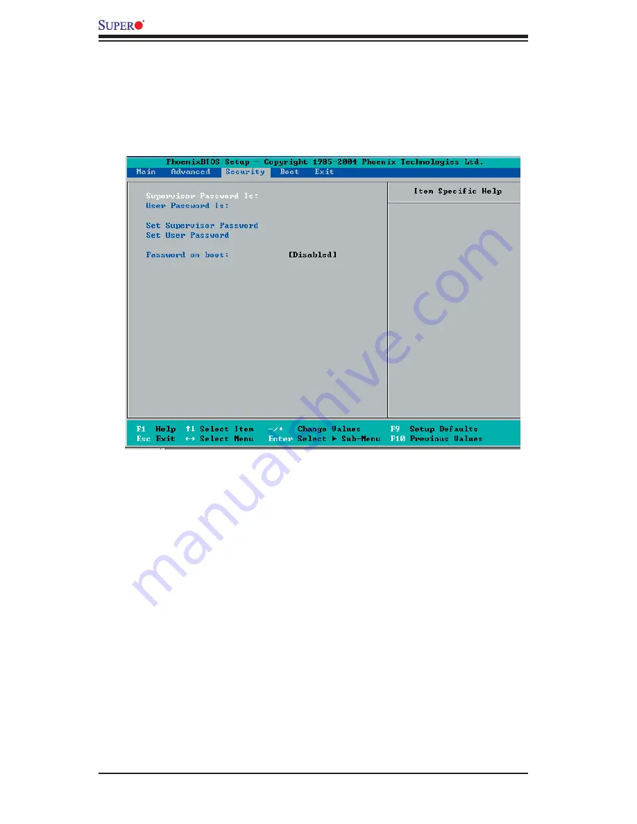
4-5 Security
Choose Security from the Phoenix BIOS Setup Utility main menu with the arrow
keys. You should see the following display. Security setting options are displayed
by highlighting the setting using the arrow keys and pressing <Enter>. All Security
BIOS settings are described in this section.
Supervisor Password Is:
This item indicates if a supervisor password has been entered to the system.
Clear means such a password has not been used, and Set means a supervisor
password has been entered.
User Password Is:
This item indicates if a user password has been entered to the system. Clear
means such a password has not been used, and Set means a user password has
been entered.
Set Supervisor Password
When the item Set "Supervisor Password" is highlighted, press <Enter>. When
prompted, type the Supervisor's password in the dialogue box to set or to change
supervisor's password, which allows access to the BIOS.
Set User Password
When the item-Set User Password is highlighted, press <Enter>. When prompted,
type the user's password in the dialogue box to set or to change the user's password,
which allows access to the system at boot-up.
Содержание PDSMU
Страница 1: ...PDSMU USER S MANUAL Revision 1 0a...
Страница 74: ...A 6 PDSMU User s Manual Notes...
Страница 80: ...B 6 PDSMU User s Manual Notes...
Страница 114: ...E 4 PDSMU User s Manual Notes...


