background image

Chapter 2: Hardware Components

2-1

Chapter 2  


Hardware Components

2-1   Expansion Card Layout and Components

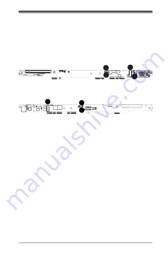
The AOC-SMG3-2H8M2-BW Top Layout

2-2   Major Components

The following major components are on the AOC-SMG3-2H8M2-BW:

A. M.2 Slot 1 Activity LED
B. M.2 Slot 1 Fault LED
C. M.2 Slot 1
D. 1.8V Indicator LED
E. M.2 Slot 2
F. M.2 Slot 2 Activity LED
G. M.2 Slot 2 Fault LED

1

C

1

B

1

A

1

D

The AOC-SMG3-2H8M2-BW Bottom Layout

E

F

G

Содержание AOC-SMG3-2H8M2-BW

Страница 1: ...User s Guide Revision 1 0 AOC SMG3 2H8M2 BW ...

Страница 2: ...lied only under a license Any use or reproduction of this product is not allowed except as expressly permitted by the terms of said license IN NO EVENT WILL SUPER MICRO COMPUTER INC BE LIABLE FOR DIRECT INDIRECT SPECIAL INCIDENTAL SPECULATIVE OR CONSEQUENTIAL DAMAGES ARISING FROM THE USE OR INABILITY TO USE THIS PRODUCT OR DOCUMENTATION EVEN IF ADVISED OF THE POSSIBILITY OF SUCH DAMAGES IN PARTICU...

Страница 3: ...on available at the time of publishing The card you have received may or may not look exactly the same as the graphics shown in this user s guide Returning Merchandise for Service A receipt or copy of your invoice marked with the date of purchase is required be fore any warranty service will be rendered You can obtain service by calling your vendor for a Returned Merchandise Authorization RMA numb...

Страница 4: ...nventions Used in the User s Guide Pay special attention to the following symbols for proper system installation and for safety instructions to prevent damage to the system or injury to yourself Note Additional information given for proper system setup ...

Страница 5: ... Super Micro Computer B V Het Sterrenbeeld 28 5215 ML s Hertogenbosch The Netherlands Tel 31 0 73 6400390 Fax 31 0 73 6416525 Email sales supermicro nl General Information support supermicro nl Technical Support rma supermicro nl Customer Support Website www supermicro nl Asia Pacific Address Super Micro Computer Inc 3F No 150 Jian 1st Rd Zhonghe Dist New Taipei City 235 Taiwan R O C Tel 886 2 822...

Страница 6: ...neral 1 1 OS Support 1 1 Physical Dimensions 1 1 Chapter 2 Hardware Components 2 1 Expansion Card Layout and Components 2 1 2 2 Major Components 2 1 2 3 Connectors and LEDs 2 2 M 2 Sockets 2 2 Activity and Fail LEDs 2 3 1 8V Indicator LED 2 3 2 4 Standoffs 2 4 Chapter 3 Installation 3 1 Static Sensitive Devices 3 1 Precautions 3 1 Unpacking 3 1 3 2 Installing Expansion Cards 3 2 Removing the M 2 C...

Страница 7: ... for the following lengths 80mm 110mm bot tom side only Auto detects SATA or NVMe M 2 Each NVMe M 2 SSD links to a full 4x PCIe Gen3 and SATA M 2 SSD links to PCH Supports activity LED onboard for each M 2 SSD Gen4 x16 PCIe slot riser card function OS Support The following operating systems and their later versions are supported Windows Linux VMware Contact Supermicro tech support at www supermicr...

Страница 8: ...OC SMG3 2H8M2 BW Top Layout 2 2 Major Components The following major components are on the AOC SMG3 2H8M2 BW A M 2 Slot 1 Activity LED B M 2 Slot 1 Fault LED C M 2 Slot 1 D 1 8V Indicator LED E M 2 Slot 2 F M 2 Slot 2 Activity LED G M 2 Slot 2 Fault LED 1 C 1 B 1 A 1 D The AOC SMG3 2H8M2 BW Bottom Layout E F G ...

Страница 9: ... 2 sockets on the expansion card designated CN1 and CN2 The card can support one SATA or NVMe SSD on CN1 or two SATA or NVMe SSDs on CN1 and CN2 A M 2 Socket 1 designated CN1 B M 2 Socket 2 designated CN2 The AOC SMG3 2H8M2 BW Top SATA NVMe Connector The AOC SMG3 2H8M2 BW Bottom SATA NVMe Connector B A ...

Страница 10: ... 2 Socket 2 LED5 Red Turns on whenever there is a drive failure on M 2 Socket 1 LED6 Red Turns on whenever there is a drive failure on M 2 Socket 2 A Activity LED designated LED2 B Fault LED designated LED5 C 1 8V Indicator LED designated LED1 D Activity LED designated LED3 E Fault LED designated LED6 The AOC SMG3 2H8M2 BW Top LEDs 1 8V Indicator LED There is one 1 8V Indicator LED on the AOC SMG3...

Страница 11: ...esigned with movable standoffs which support two different M 2 SSD lengths Place the standoffs as indicated below M 2 Length Standoff Positions 22mm x 80mm 1 22mm x 80mm 2 22mm x 110mm 3 1 1 1 3 1 2 The AOC SMG3 2H8M2 BW Top Standoff Positions The AOC SMG3 2H8M2 BW Bottom Standoff Positions ...

Страница 12: ...le the expansion card by its edges only do not touch its components or peripheral chips Put the expansion card back into the antistatic bags when not in use For grounding purposes make sure that your system chassis provides excellent conductivity between the power supply the case the mounting fasteners and the expansion card Unpacking The expansion card is shipped in antistatic packaging to avoid ...

Страница 13: ...ng Expansion Cards 1 Power down the system and remove the power cord from the rear of the power supply 2 Use industry standard anti static equipment such as gloves or wrist strap and follow the precautions on page 3 1 to avoid damage caused by ESD 3 For the first SSD unscrew the metal standoff from the 80mm hole on the top side of the carrier card Figure 1 Selecting the Standoff Hole 4 Insert the ...

Страница 14: ...doff Figure 3 Inserting the Standoff Figure 4 Inserting the Second SSD 6 Secure the SSD in place by screwing in the metal standoff 7 If installing a second SSD repeat steps 3 6 on the bottom side of the carrier card using either the 80mm or 110mm hole and the bottom side M 2 slot ...

Страница 15: ...otherboard remove any DIMMs obstructing access to the carrier card slot 10 Push the carrier card into the slot on the motherboard With the screws pro vided secure it to the side of the node chassis 11 Replace any DIMMs that may have been removed 12 Replace the node into the chassis and power up the system Figure 5 Locating the M 2 Carrier Card Slot and Screws ...

Страница 16: ...n angle before removing it from the M 2 slot Figure 6 Removing the Carrier Card Removing the M 2 Carrier Card If an M 2 carrier card is installed in your server remove it to add M 2 solid state devices SSDs To Remove the M 2 Carrier Card 1 Power down the node and remove it from the chassis 2 Remove any DIMMs obstructing access to the carrier card 3 Remove the two screws from the left side viewed f...

Страница 17: ...e CPU IOU settings set to x4x4x4x4 PCIe bifurcation This option may be found under BIOS Setup Advanced Chipset Configuration North Bridge IIO Configuration CPU Configuration IOU Setting x4x4x4x4 Having the NVMe Firmware Source set to AMI Native Support This option may be found under BIOS Setup Advanced PCIe PCI PnP Configuration NVMe Firmware Source AMI Native Support Refer to the applicable syste...

Отзывы: