Superior SLO-SYN SS2000MD4 Скачать руководство пользователя страница 6

Danaher Motion Superior Electric

SS2000MD4 

400030-043 Rev G

 SECTION 1: INTRODUCTION 


1.1 U

SING 

T

HIS 

M

ANUAL


It is important that you understand how this SLO-SYN

®

 2000MD4 Translator/Drive is 

installed and operated before you attempt to use it. R

ead this manual completely before 

proceeding with the installation of this unit.


This manual is an installation and operating guide to the SLO-SYN 2000MD4 
Translator/Drive. Section 1 gives an overview of the Drive and its features. Section 2 
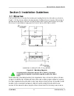
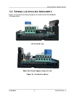
describes the steps necessary to place the drive into operation. General wiring guidelines 
as well as the physical mounting of the unit and connections to the drive portion are 
covered in Section 3. 
Complete specifications, listed in Section 4, provide electrical, mechanical and 
performance specifications. The procedure for setting the motor current level is also 
covered in this section.  
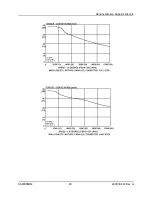
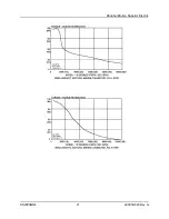
Torque versus speed characteristics with all appropriate SLO-SYN Stepper Motors are 
given in Section 5. Section 6, System Checking, gives procedures to follow if the SLO-
SYN 2000 drive fails to operate properly. 
Appendix A provides procedures for troubleshooting electrical interference problems. 

 1.2 P

RODUCT 

F

EATURES


SLO-SYN 2000MD4 Translator/Drive is a bipolar, adjustable speed, two-phase PWM 
drive that uses hybrid power devices. It can be set to operate a step motor in full steps or 
half steps. The maximum running speed is 3,000 rpm. To reduce the chances of electrical 
noise problems, the control signals are optically isolated from the drive circuit. Features 
include: 

Switch selectable current levels of 0.5 through 3.5 amperes 
Full short circuit protection (phase-to-phase and phase-to-ground) 
Undervoltage and transient overvoltage protection 
Efficient thermal design 
Optically isolated inputs 
Windings Off capability 
Switch selectable step resolution 
Compact size 
Sturdy all-aluminum mounting base 

Содержание SLO-SYN SS2000MD4

Страница 1: ...www DanaherMotion com Installation Instructions for SLO SYN MODEL SS2000MD4 Translator Drive 400030 043 Rev G...

Страница 2: ...hout the written permission from the publisher While every precaution has been taken in the preparation of the book the publisher assumes no responsibility for errors or omissions Neither is any liabi...

Страница 3: ...ns Warranty And Limitation Of Liability Danaher Motion the Company warrants to the first end user purchaser the purchaser of equipment manufactured by the Company that such equipment if new unused and...

Страница 4: ...TO ANY PERSON OR PROPERTY Written authorization to return any equipment or parts thereof must be obtained from the Company The Company shall not be responsible for any transportation charges IF FOR AN...

Страница 5: ...13 4 1 MECHANICAL 13 4 2 ELECTRICAL 13 4 3 ENVIRONMENTAL 13 4 4 MOTOR COMPATIBILITY 13 4 5 CURRENT SETTINGS 15 4 6 STEP RESOLUTION 15 4 7 SIGNAL SPECIFICATIONS 16 4 7 1 CONNECTOR PIN ASSIGNMENTS 16 4...

Страница 6: ...l is also covered in this section Torque versus speed characteristics with all appropriate SLO SYN Stepper Motors are given in Section 5 Section 6 System Checking gives procedures to follow if the SLO...

Страница 7: ...ection 4 4 for a list of compatible motors 2 Set the correct current level for the motor being used per the instructions in Section 4 5 Heat sinking may be required to maintain case temperature below...

Страница 8: ...better to use too little than too much Figure 3 1 Mounting Diagram Case temperature should not exceed 70 C 158 F Forced air cooling may be required to maintain temperature within the stated limits Wh...

Страница 9: ...SS2000MD4 9 400030 043 Rev G 3 2 TERMINAL LOCATIONS AND ASSIGNMENTS Figure 3 2 shows the terminal locations for the SLO SYN SS2000MD4 Translator Drive I O Connector J2 Motor And Power Supply Connector...

Страница 10: ...and motor phase B is M4 and M5 The motor frame must be grounded Cabling from the drive to the motor should be done with a shielded twisted pair cable As a guideline the wires for each motor phase sho...

Страница 11: ...ORANGE E GREEN C WHITE GREEN 6 2 7 8 DRIVE PIN 1 DRIVE PIN 2 DRIVE PIN 1 DRIVE PIN 2 DRIVE PIN 1 DRIVE PIN 2 DRIVE PIN 4 DRIVE PIN 3 DRIVE PIN 4 DRIVE PIN 3 DRIVE PIN 4 DRIVE PIN 3 D F B H 5 4 1 3 WH...

Страница 12: ...correct value and have the proper current and voltage parameters see list of components It is recommended that the power supply leads be twisted together 6 twists per foot If the power supply is groun...

Страница 13: ...must be maintained Forced air cooling may be required Storage 40 F to 167 F 40 C to 75 C Humidity 95 max non condensing Altitude 10 000 feet 3048 m max 4 4 MOTOR COMPATIBILITY Motor Types Superior El...

Страница 14: ...9 Parallel 3 5 1 0 3 0 KML060FO5 2 5 1 0 1 5 KML061FO5 2 5 1 2 1 5 KML061F11 3 5 1 0 3 0 KML062F07 3 0 1 0 2 5 KML062F13 3 5 1 0 4 0 KML063F07 3 0 1 5 2 0 KML063F13 3 5 1 0 4 0 KML091F07 3 0 1 0 2 0 K...

Страница 15: ...If two or more switches are ON the one that selects the highest current level is the active switch The switch settings are Position Current amperes None 0 5 1 0 75 2 1 0 3 1 5 4 2 0 5 2 5 6 3 0 7 3 5...

Страница 16: ...is high motor rotation is clockwise Motor rotation is counter clockwise when this signal is low Clockwise and counter clockwise directions are properly oriented when viewing the motor from the end op...

Страница 17: ...5V OPTO IN PULSE DRIVE SWITCH OPTO 5V GND OPTO IN PULSE DRIVE 560 ohms 1 4 watt 12 VDC 16 mA PER SIGNAL CONTROL SIGNAL CONTROL LOGIC COMMON 4 5 6 0 VDC 16 mA PER SIGNAL OPTO IN PULSE DRIVE CONTROL SIG...

Страница 18: ...ping of the system and acceleration deceleration through the resonance areas aid in reducing instability to a level that provides smooth shaft velocity and accurate positioning If instability does cau...

Страница 19: ...n Superior Electric SS2000MD4 19 400030 043 Rev G 5 2 TYPICAL TORQUE VERSUS SPEED CURVES The test conditions used when obtaining the torque versus speed data are listed in the lower left hand corner o...

Страница 20: ...Danaher Motion Superior Electric SS2000MD4 20 400030 043 Rev G...

Страница 21: ...Danaher Motion Superior Electric SS2000MD4 21 400030 043 Rev G...

Страница 22: ...Danaher Motion Superior Electric SS2000MD4 22 400030 043 Rev G...

Страница 23: ...Danaher Motion Superior Electric SS2000MD4 23 400030 043 Rev G...

Страница 24: ...Danaher Motion Superior Electric SS2000MD4 24 400030 043 Rev G...

Страница 25: ...Danaher Motion Superior Electric SS2000MD4 25 400030 043 Rev G...

Страница 26: ...Danaher Motion Superior Electric SS2000MD4 26 400030 043 Rev G...

Страница 27: ...Danaher Motion Superior Electric SS2000MD4 27 400030 043 Rev G...

Страница 28: ...Danaher Motion Superior Electric SS2000MD4 28 400030 043 Rev G...

Страница 29: ...Danaher Motion Superior Electric SS2000MD4 29 400030 043 Rev G...

Страница 30: ...Danaher Motion Superior Electric SS2000MD4 30 400030 043 Rev G...

Страница 31: ...Danaher Motion Superior Electric SS2000MD4 31 400030 043 Rev G...

Страница 32: ...Danaher Motion Superior Electric SS2000MD4 32 400030 043 Rev G...

Страница 33: ...Danaher Motion Superior Electric SS2000MD4 33 400030 043 Rev G...

Страница 34: ...Danaher Motion Superior Electric SS2000MD4 34 400030 043 Rev G...

Страница 35: ...to the unit Be sure that the motor is a correct model for use with this unit Specifically IF MOTOR DIRECTION CW CCW IS REVERSED Check For Reversed connections to the Motor Connector Reversing the phas...

Страница 36: ...ise sources switched off If the drive functions properly switch the noise sources on again one at a time and try to isolate the one s causing the interference problems When a noise source is located t...

Отзывы: