


www.SuperiorFireplaces.US.com
126903-01A
8
INSTALLATION
Continued
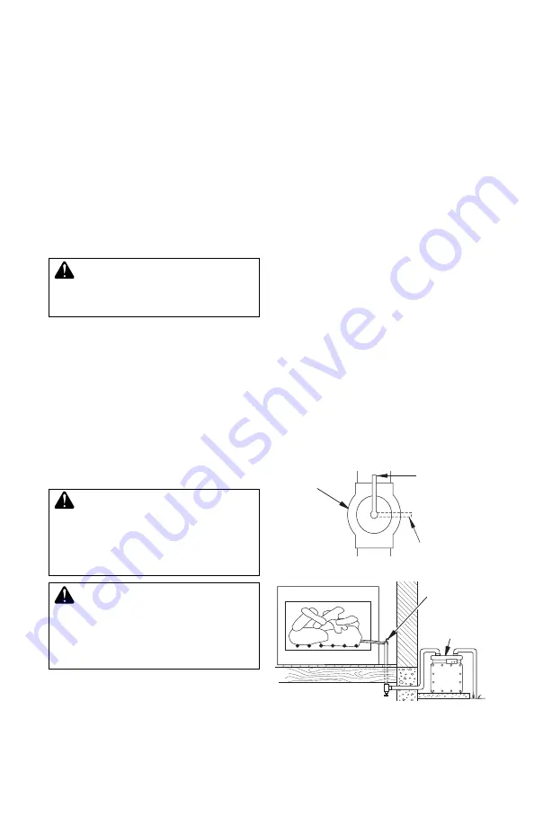
Installation must include an equipment shutoff
valve, union and plugged 1/8" NPT tap. Locate
NPT tap within reach for test gauge hook up.
NPT tap must be upstream from log set (see
Figure 4).
IMPORTANT:
Install equipment shutoff valve
in an accessible location. The equipment
shutoff valve is for turning on or shutting off
the gas to the appliance.
Apply pipe joint sealant lightly to male NPT
threads. This will prevent excess sealant from
going into pipe. Excess sealant in pipe could
result in a clogged burner injector.
WARNING: Use pipe joint
sealant that is resistant to liquid
petroleum (LP) gas.
We recommend that you install a sediment
trap (not supplied with log set) in supply line
as shown in Figure 4, page 7. Locate sediment
trap where it is within reach for cleaning. Install
in piping system between fuel supply and ap
-
pliance. Locate sediment trap where trapped
matter is not likely to freeze. A sediment trap
captures moisture and contaminants. This
keeps them from going into log set controls.
If sediment trap is not installed or is installed
wrong, log set may not run properly.
CHECKING GAS CONNECTIONS
WARNING: Test all gas piping
and connections, internal and
external to unit, for leaks after
installing or servicing. Correct
all leaks at once.
WARNING: Never use an open
flame to check for a leak. Apply a
noncorrosive leak detection fluid
to all joints. Bubbles forming show
a leak. Correct all leaks at once.
Pressure Testing Gas Supply Piping
System
Test Pressures In Excess Of 1/2 PSIG
(3.5 kPa)
1. Disconnect appliance with its appliance
main gas valve (control valve) and equip-
ment shutoff valve from gas supply piping
Figure 6 - Checking Gas Joints
Gas Meter
Equipment
Shutoff
Valve
system. Pressures in excess of 1/2 psig
3.5 kPa) will damage appliance regulator.
2. Cap off open end of gas pipe where equip
-
ment shutoff valve was connected.
3. Pressurize supply piping system by either
using compressed air or opening main gas
valve located on or near gas meter.
4. Check all joints of gas supply piping sys
-
tem. Apply noncorrosive leak detection
fluid to gas joints. Bubbles forming show
a leak.
5. Correct all leaks at once.
6. Reconnect log set and equipment shutoff
valve to gas supply. Check reconnected
fittings for leaks.
Test Pressures Equal To or Less Than
1/2 PSIG (3.5 kPa)
1. Close equipment shutoff valve (see Fig-
ure 5).
2. Pressurize supply piping system by either
using compressed air or opening main gas
valve located on or near gas meter.
3. Check all joints from gas meter to equip
-
ment shutoff valve (see Figure 5). Apply
mixture of liquid soap and water to gas
joints. Bubbles forming show a leak.
4. Correct all leaks at once.
www.fmiproducts.com
115425-01F
8
INSTALLATION
Continued
Figure 6 - Checking Gas Joints
Gas Meter
Equipment
Shutoff Valve
HEARTH KIT ASSEMBLY AND
INSTALLATION
Kit Assembly - Ramp Pan Burner
1. Determine which side gas line feeds into
fireplace.
This log set is factory set up for
right side (facing) gas feed. If your gas line
is on the right side, go to
Installation and
Gas Connection
. If your gas line is on the
left side of
fireplace,
proceed with steps 2
through 4 below.
2. Remove nuts securing gas inlet venturi to
bottom of burner.
3. Remove venturi from pan taking care not to
damage gasket between venturi and pan.
4. Reverse direction of venturi and reattach
to bottom of pan using factory nuts.
Figure 7 - Venturi Gas Connection
Burner Orifice
(Factory Installed)
Burner Inlet Venturi
(Attached to Pan
Bottom)
Gas Connector
Tube
Adapter
Fitting
Burner Inlet Fitting
(Factory Installed)
Installation and Gas Connection
1. Place ramp burner assembly in center
of
fireplace
floo
r. Make sure front of pan
faces forward.
2. Thread gas supply
fitt
ing to
fi
replace gas
supply pipe. Use thread sealant.
3. Install gas connector tube to gas supply
fitting.
Carefully shape tube to attach to
adapter
fitting.
Be careful not to cause
kinks in tube.
4. Attach opposite end of gas connector tube
to gas inlet fitting on end of venturi.
Test Pressures Equal To or Less Than
1/2 PSIG (3.5 kPa)
1. Close equipment shutoff valve (see Fig-
ure 5).
2. Pressurize supply piping system by either
using compressed air or opening main gas
valve located on or near gas meter.
3. Check all joints from gas meter to equip-
ment shutoff valve (see Figure 6). Apply
noncorrosive leak detection
fluid
to gas
joints. Bubbles forming show a leak.
4. Correct all leaks at once.
TESTING BURNER FOR LEAKS
1. Generously apply noncorrosive leak
detection
fl
uid to all connections.
WARNING: Never check for
gas leaks with ope
n fl
ame.
2. Light burner with shutoff valve no more
than half open and holding a match
slightly in front of pan (see
Lighting In-
structions
, page 10).
3. Inspect all connections for bubbles, raw
gas odor, or
fl
ame from any area other than
burner (leaks). If leaks are detected, shut
off gas valve immediately. Tighten, or reas-
semble loose connection(s) using pipe joint
compound until burner system is leak free.
4. When burner is tested and leak free, ob-
.
r
e
n
r
u
b
n
o
e
m
a
fl
f
o
s
e
u
g
n
o
t l
a
u
d
i
v
i
d
n
i
e
v
r
e
s
Make sure all ports are clear and producing
fl
ame evenly across burner. If any ports
appear blocked, clear by removing burner
manifold and reaming ports with a modi
fi
ed
paper clip or other suitable tool.
5. When
finished
testing, turn gas shutoff
valve OFF to extinguish all flames.
Figure 5 - Equipment Shutoff Valve
Open
Closed
Equipment
Shutoff
Valve


