background image

2

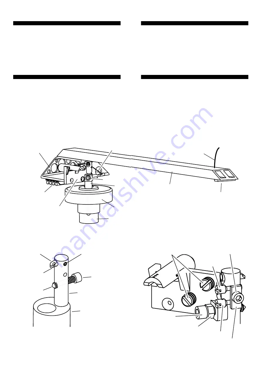
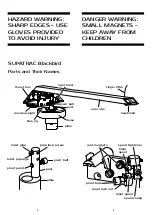
SUPATRAC Blackbird  

Parts and Their Names

hoist pipe

hoist pipe eye

pipe lock screw

pivot bolt

pivot point

post

pillar

HAZARD WARNING: 
SHARP EDGES - USE 
GLOVES PROVIDED 
TO AVOID INJURY

base

pillar

arm tube

headshell

counterweight

right hoist

post

thrust box

bias rig

finger lifter

pivot bolt

3

spool tightener

pivot lock nut

hoist spool

pivot bolt

spool clamp

rest magnets

hoist

spool

DANGER WARNING: 
SMALL MAGNETS - 
KEEP AWAY FROM 
CHILDREN

base

pillar

arm tube

headshell

counterweight

right hoist

post

thrust box

bias rig

finger lifter

pivot bolt

Содержание Blackbird

Страница 1: ...Instructions Warranty Blackbird SUPATRAC supatrac com ...

Страница 2: ...oses the drag on the stylus so that the energy and timing of musical recordings is reproduced with exquisite accuracy This manual explains how to install and set up your Blackbird Sideways Uni Pivot Arm for best performance INDEX Diagrammes page 2 Box contents page 4 Carriage page 4 Installation page 5 Set up page 13 Maintenance page 17 Solving problems page 19 Disassembly page 20 Further informat...

Страница 3: ...AVOID INJURY base pillar arm tube headshell counterweight right hoist post thrust box bias rig finger lifter pivot bolt 3 spool tightener pivot lock nut hoist spool pivot bolt spool clamp rest magnets hoist spool DANGER WARNING SMALL MAGNETS KEEP AWAY FROM CHILDREN base pillar arm tube headshell counterweight right hoist post thrust box bias rig finger lifter pivot bolt ...

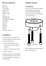
Страница 4: ...olded handkerchief or other cushion between the pivot point and thrust plate 2 stabilise the arm with a support or tape 3 attach a stylus guard For longer journeys it is recommended that you remove the arm from the post so that it can be packed separately See the section on Disassembly 4 INSTALLATION Install Base Attach the base to the arm board or plinth of your turntable using the M5 bolts provi...

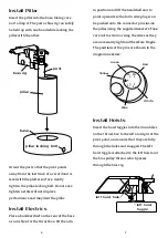
Страница 5: ... pillar locking bolt base bias rig post 6 in position and lift the headshell end to point upwards so that arm wire plugs can be pushed onto the connector pins inside the pillar using the supplied tweezers Take care not to strain or snag the wires as they are necessarily light and therefore fragile The positions of the pins are shown in the diagramme below Install Hoists Insert the hoist toggles in...

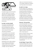
Страница 6: ...e achieved by trial and error or by calculation Blackbird has an effective mass of 11g without the inertia adjuster Install Cartridge Two bolt cartridges can be installed in the normal way Placing a folded handkerchief between the pivot point and thrust box protects the pivot point It is therefore not necessary to dismount the arm for cartridge installation For a three bolt cartridge remove the fi...

Страница 7: ...ulley the bias rotor s three holes as illustrated is normally enough to grip the bias thread but allow it to slip when forced The overall amount of bias is set by tightening or loosing the grub screw inside the rotor The further the grub screw is from the rotor s axle the more bias will be applied Do not tighten as far as the axle Finally it is possible to adjust bias by rotating the pillar in the...

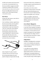
Страница 8: ... lean azimuth and adjusting the arm s geometry to ensure that all are optimal Downforce Inertia Set downforce and inertia using the counterweight which attaches magnetically to the underside of the thrust box and the inertia adjuster which sits across the arm like a saddle between the cartridge and pivot The further both weights are from the pivot the higher will be the arm s inertia effective mas...

Страница 9: ...usted by shortening or loosing the left and right hoists using the hoist spools 15 stylus resting in the dimple corresponding to your desired downforce Blackbird s low pivot means that your stylus should maintain contact with the record even at minimum recommended downforce or lower Consistent tracking with low downforce can reduce wear on records and styluses Bias Tuning Bias is required to ensur...

Страница 10: ...ORTANT there is a correct height for the suspended arm the pivot point must make contact with the thrust box on the straight line between the two points where the hoists meet the thrust box To ensure this cut a 6cm by 1cm rectangle from the corner of a straight edged piece of paper insert it between the hoists and the thrust box and raise the headshell so that the paper s straight edge sits on the...

Страница 11: ...t so that its eye is more directly above the pivot point The bearing works best if the eye of the hoist pipe is only a millimetre or so closer to the post than the pivot point Do not over extend the hoist pipe lest contact at the pivot cease Excess Bias This problem may also arise from the eye of the hoist pipe being too near the post as compared to the pivot Extend the hoist pipe as described abo...

Страница 12: ...he electrical contacts by gripping the plugs with tweezers not the wires and gently pull them upwards until they detach 4 The arm is now detached and can be stored somewhere safe 5 Unplug the arm cable from the bottom of the pillar 6 Loosen the pillar locking bolt taking care not to allow the pillar to drop and remove the pillar 7 Unbolt the base FURTHER INFORMATION For further information please ...

Отзывы: