10
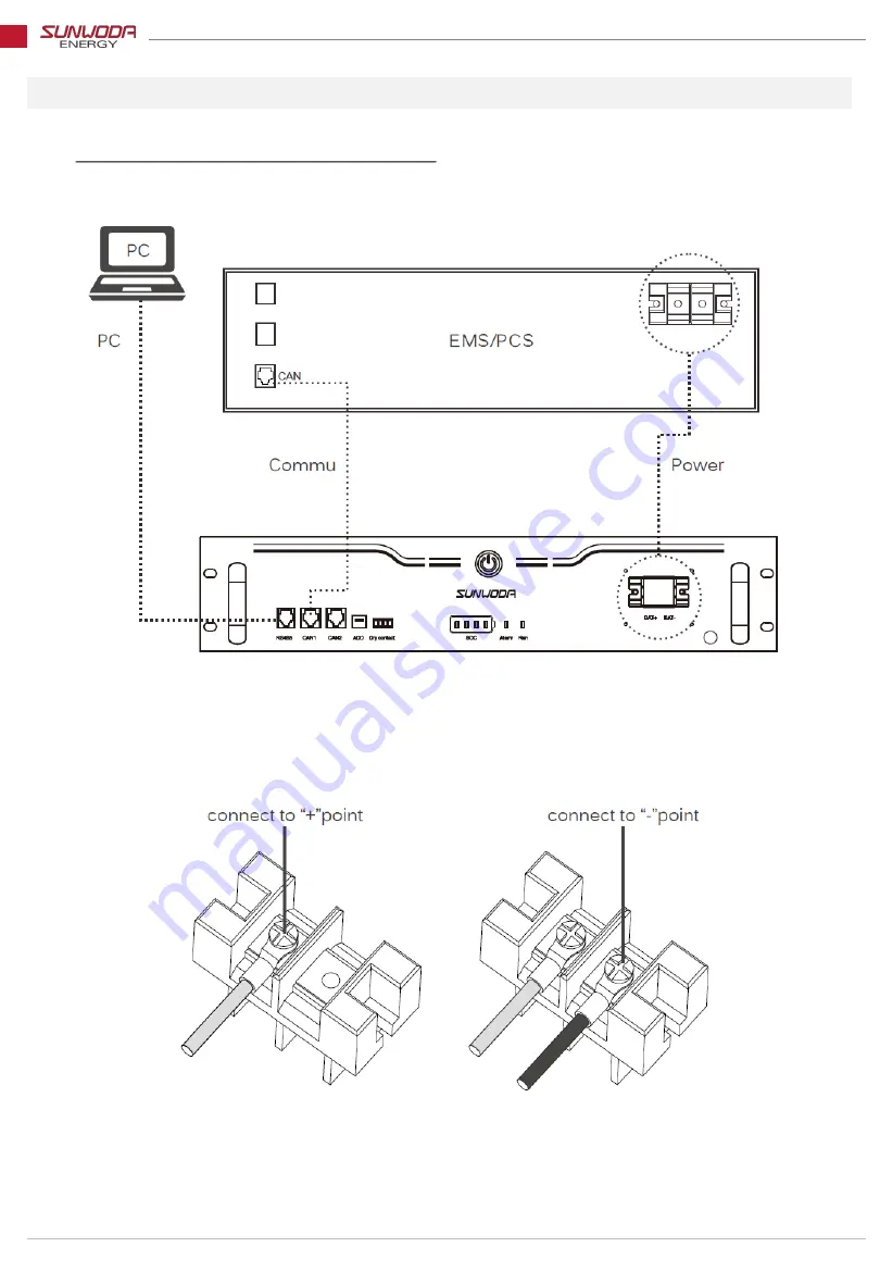
3.3 Cable connection (Single module with EMS)
- Instruction Manual for NEO pro B4180 Module -
Fig. 3. Power cable connection diagram
Страница 1: ...Instruction Manual For use with Sunwoda NEO pro B4850 module Model No H4850M P01...
Страница 2: ...s 3 2 2 Quick Start 4 2 3 Function Description 7 3 Installation guide 9 3 1 In the box 9 3 2 Pre installation notices 10 3 3 Connection 11 4 Product Data Sheets 13 5 FAQ and trouble shooting 14 6 Main...
Страница 3: ...ter or condensation 2 Do not place the battery on or near fires or other high temperature locations 70 C Doing so may cause the battery to overheat or ignite Using the battery in this manner may also...
Страница 4: ...2 Product handling information 3 2 1 Product dimensions mm Instruction Manual for NEO pro B4180 Module Fig 1 Battery pack dimension...
Страница 5: ...r DIP Switch 6 Dry node Dry node interface for battery pack output Reserve 7 On off button Press to switch Battery pack on off mode 8 Brand logo Logo of manufacturer 9 State indicator Indicating capac...
Страница 6: ...s Indicating SOC in 25 percentage per LED 2 Alarm Indicator Illuminates in case of error detected 3 Run Indicator Lights up when system is running properly Table 1 Front panel features indicators Fig...
Страница 7: ...address setting 1 2 Address 2 Battery address setting 2 3 Address 3 Battery address setting 3 4 Working Mode Working Mode Setting Flick the switch to ON position to get an 1 address value Otherwise th...
Страница 8: ...76 99 Alarm Warning Undervoltage warning Overvoltage warning Blinking in Red colour Different combinations of the 4 LEDs indicate different warning as shown in the table Overcurrent charging Overcurre...
Страница 9: ...ng High temp protect MOSFET Short circuit protect Charging Low battery warning Short circuit protect Discharging Blinking in blue Errors Dysfunctions MOSFET Charging error MOSFET discharging error Vol...
Страница 10: ...s and corrosives 3 Avoid long hour installation in corrosive environment 4 Avoid direct sun explosion 5 If installed in low temperature environment it might be subject to water condensation Don t cont...
Страница 11: ...10 3 3 Cable connection Single module with EMS Instruction Manual for NEO pro B4180 Module Fig 3 Power cable connection diagram...
Страница 12: ...11 Instruction Manual for NEO pro B4180 Module Fig 4 Grounding connection Fig 5 DIP set to 0001...
Страница 13: ...le connection diagram Fig 7 DIP Switch setting in parallel mode For multi lithium battery systems the 4th value is fixed at 0 the first three values can be varied from 000 111 each representing an add...
Страница 14: ...ingle cell temperature 55 Restores as it drops by 5 High discharge temp protect Single cell temperature 60 Restores as it drops by 5 Low charge temp protect Single cell temperature 0 Restores as it dr...
Страница 15: ...process 1 Model number 2 Serial number 3 Fault occurring date 4 Complete problem description including indicating buzzing power supply load capacity etc 14 Instruction Manual for NEO pro B4180 Module...
Страница 16: ...city is optimal Monthly charge and discharge is proposed in order to increase battery life Routine maintenance Undercharge is forbid in time of battery storing undercharge means the battery is not cha...
Страница 17: ...ill be at the user s charge If any of following facts occurs the warrant doesn t apply Damages due to human causes like inappropriate installation and operation The device is repaired changed or modif...
Страница 18: ...the respective characteristics shall only exist if expressly agreed in the terms of contract All product designations may be trademarks or product names of Sunwoda Energy or supplier companies whose u...