background image

19

66

AMP Box Installation

1) AMP box installation

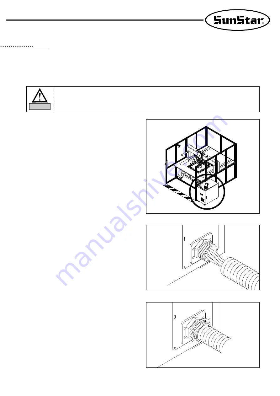
[ Fig. 11 ]

Please unplug during the installation of AMP box. 
Plastic connector can be damaged when connecting cable, so please proceed with caution.
Please lock the cover after installing AMP box not to open it arbitrarily.

Caution

A. AMP box is on the front right side of the sewing machine.

Follow the instructions below to connect cables from the
machine and fix the AMP box.

[ Fig. 12 ]

B. Insert sewing machine connection cable into the cable

entrance at the back of the AMP box.

To turn the handle of the cable holder when inserting
cable, the cable tube can be inserted easily. [See Pic. 13]

Plastic connector can be damaged when connecting
cable, so please proceed with caution.

[ Fig. 13 ]

C. Please fix the cable tube by turning the handle of the cable

holder after inserting cable.

Содержание SPS/E-8050 Series SPS/HT-5050B1 Series

Страница 1: ... BEFORE STARTING USE 2 KEEP THIS MANUAL IN SAFE PLACE FOR REFERENCE WHEN THE MACHINE BREAKS DOWN M MM ME E 1 11 10 05 52 27 7 USER S MANUAL R S Su un nS St ta ar r C CO O L LT TD D SPS HT 5050B1 Series Electronically Controlled Rotary Head Auto Pattern Sewing Machine ...

Страница 2: ...ing the cutting edge electronic control pattern sewing machine with various functions flawless performance powerful force improved durability 2 Please read this user s manual thoroughly before using the machine Make sure to properly use the machine to enjoy its full performance 3 The specifications of the machine are subject to change aimed to enhance product performance without prior notice 4 Thi...

Страница 3: ...PATTERN S M Model Series Patterns S Se er riie es s S Se ew wiin ng g r ra an ng ge e X X 1 10 0m mm m Y Y 1 10 0m mm m P Pu ur rp po os se es s SPS HT 50 50 B1 01 ...

Страница 4: ...d of oil supply 14 1 Oil Supply 14 5 Installing the machine 15 1 Conditions for installing the machine 15 2 Conditions for power supply 15 3 Assembling peripheral devices 15 6 AMP Box Installation 19 1 AMP box installation 19 2 AMP box interior cable connection 20 7 Voltage Specifications Change 23 1 Voltage specifications 23 2 Check voltage display LED 23 3 Auxiliary breaker action 24 8 AMP Box C...

Страница 5: ... 32 12 Adjustment of Hook Needle Guide Position 32 13 Clearance adjustment of hook and opener 33 14 Lubrication adjustment of hook 33 15 Trimmer 34 16 Adjusting tension of operating belt 36 17 Setting X Y Original Point 38 18 Air system 39 11 Preparation before starting operation 40 1 Inserting needle 40 2 Inserting upper thread 40 3 How to Adjust the Upper Thread Tension 41 4 How to Adjust the Lo...

Страница 6: ...er could prevent expected malfunction Caution Warning Danger Only personnel with a full understanding of the safety rules should move the machines The following directions must be observed when moving the machines 1 Delivery by men In the case the worker should wear safety shoes and hold tightly on the left and right sides 2 Delivery by forklift The forklift should sustain the weight of the machin...

Страница 7: ...ane Make sure that the crane is large enough to hold the machine Use a nylon rope of sufficient strength Place a wooden block at either side of the machine before tying the rope The angle should be 40 or less Make sure that the rope does not touch the table Make sure all persons and obstacles are out of the way of the moving equipment Nylon rope Wooden block Max 40 Max 40 ...

Страница 8: ...es and breakdowns are likely to occur according to the environment in which the machine is being installed Therefore the following preconditions should be fulfilled 1 The worktable or desk on which the machine would be installed should be strong enough to sustain the weight see the nameplate of the machine 2 Because machines are apt to be contaminated and corroded by dust and moisture you should i...

Страница 9: ...ce the damaged part with the genuine parts of our company SunStar 4 After repair please put again the safety covers disjointed during repairing 5 Machine troubleshooting Danger Caution For main motor X Y drive box it takes 10 minutes to discharge completely after the power is shut off Instructions here should be observed Otherwise the user could face mechanical damages such as the functional obsta...

Страница 10: ...ies or changing of needles WARNING WARNING Physical damage may be caused by interposition While embroidery frame is running according to the direction of embroidery frame may be injured your hands by gap between fixed body and embroidery frame First of all press the safety switch during inspection and operation of the machine WARNING Put a safety sticker on the floor when installing the machine Do...

Страница 11: ...ding to the direction of embroidery frame may be injured your hands by gap between fixed body and embroidery frame WARNING WARNING Be careful not to be smashed against the rotating machine during sewing operation Inter rock Door Do not open this door while Machine is running since It is an inter rock door WARNING WARNING Area sensor In operation Area sensor Accessing the machine when in operation ...

Страница 12: ...SPS HT 5050B1 SPS HT 8050B1 X 500mm Y 500mm X 800mm Y 500mm 2 200 spm below 3mm of stitch length 0 05 12 7mm Min 0 05mm Feeding by servo motor 41 2 mm DP 17 DP 5 Average 4mm 0 7 7mm 22 mm 50 mm 2 5 times hook Bobbin for 2 5 times hook USB flash drive Availability of emergency stop during sewing operation Availability of speed limitation from 1 800spm to 2 200spm Availability of selecting pattern n...

Страница 13: ... on off Arm Table Control box Operation box USB Port Start switch Upper feed panel driven switch Body Emergency stop switch Thread stand Defensor Defensor Safety Sensor Defensor Safety Switch Defensor Safety Tape 1 Name of parts Fig 1 ...

Страница 14: ... the table and supply enough oil through the oil inlet One time per week once a week Fig 2 Fig 3 Fig 8 Make sure to supply oil when using the machine for the first time or after not using it for a long time Caution 1 Before lubricating press the safety switch of machine and supply oil 2 Please supply oil in case of first use or not use the machine for a long time There is a danger of burning witho...

Страница 15: ...ay once a week D Open a slide and supply oil to soak into a hook E Fill to the tank of oil of the arm fig 2 and of the bed fig 3 1 time to the week and lubricate the part superior of the arm fig 4 and the environs of the hook fig 5 1 time to the day One time per day once a day Fig 5 Fig 4 ...

Страница 16: ... humidity 2 Conditions for power supply A Voltage Voltage should be within 10 percent of the rated voltage Frequency should be within 1 percent of the rated frequency 50 60Hz B Electromagnetic wave noise It is required for the machine not to share power with products releasing strong magnetism and high frequency and to keep the machine away from them C Make sure to use safe low voltage when it is ...

Страница 17: ...horse ⓑ Link quick joint socket to quick joint plug ⓒ Open valve to inflow air and adjust air pressure to 4 5 5 5kgf cm2 0 44 0 54MPa Note When closing valve after use the remaining air will automatically go out with the remaining pressure displayed at 0kgf cm2 0MPa For the safety do work with the power switch off Caution When the air pressure is low under 4kgf cm2 during operation the machine sto...

Страница 18: ... of A at 90 Combine them on the upper face using ㄱ type bracket and combine the side using ㄴ type bracket ⓔ Two Cs interact the center of the combined A like figure and combine them to the upper and lower face using ㄴ type bracket Then combine the side using ㄴ type bracket E Installation Methods of Defensor Safety Sensor ⓐ Fasten the enclosed sensor bracket in the defensor components box on the sp...

Страница 19: ...t side of the sewing machine Follow the instructions below to connect cables from the machine and fix the AMP box Fig 12 B Insert sewing machine connection cable into the cable entrance at the back of the AMP box To turn the handle of the cable holder when inserting cable the cable tube can be inserted easily See Pic 13 Plastic connector can be damaged when connecting cable so please proceed with ...

Страница 20: ...low Fig 14 No Cable connection location main power and motor cable connection main motor encoder cable connection sensor and pneumatic signal cable connection Please check the connector color when connecting cables to the connector then connect them to the connector of the same color Do not pull the cables when disconnecting connector This causes the cable disconnection Caution ...

Страница 21: ...CA 005187 CA 005188 CA 005189 CA 005190 CA 005191 CA 005192 CA 005193 CA 005194 CA 005195 CA 005196 CA 005199 CA 005158 CA 005201 Connection cable name X axis motor encoder B cable X axis motor output B cable Y axis motor encoder B cable Y axis motor output B cable head turning upper shaft motor encoder B cable head turning upper shaft motor output B cable head turning lower shaft motor encoder B ...

Страница 22: ...OW SW Connector color WHITE RED WHITE RED WHITE WHITE YELLOW YELLOW RED RED WHITE WHITE Connection cable CA 005388 CA 005377 CA 005208 CA 005206 CA 005207 CA 005381 CA 005204 CA 005205 CA 005393 CA 005391 CA 005204 CA 005203 Connection cable name Lower shaft synchro sensor intermediate coupling cable XY sensor intermediate coupling cable HEAD sensor intermediate coupling cable Emergency stop switc...

Страница 23: ...3 AC160 Below AC160 Voltage status overvoltage Circuit breaker turns off the power overvoltage Normal voltage low voltage low voltage Circuit breaker turns off the power of the control box Input Voltage this indicates the secondary voltage of the transformer in the AMP box and output voltage through the transformer when the user inputs the AC 200 240V Do not use under the different voltage conditi...

Страница 24: ...pecifications C If the sewing machine powers on and the LED lights in green the voltage is normal If the LED lights in yellow or red the input voltage is not consistent with the specifications Fig 19 Do not use the breaker switch as the power switch Please operate breaker switch manually When the breaker works frequently please contact our repair center engineer Caution ...

Страница 25: ...otor drive R AMP Head turning lower shaft motor drive R AMP Lower shaft motor drive R AMP X axis motor drive R AMP Y axis motor drive R AMP Voltageindicator board Main motor drive board Control box Transformer B Left side interior AMP box configuration Fig 21 No Name Motor and power connector board Main motor encoder connector Control box ...

Страница 26: ...23 No Description Start a stitch with READY status Clamp movement switch Emergency stop switch Decide whether thread trimming code included in the sewing design is on or not Red lamp ON Thread trimming during sewing Red lamp OFF No thread trimming during sewing Thread trimming switch during sewing E Back AMP box configuration Fig 24 No Name Auxiliary breaker switch AMP box FAN Cable entrance Name ...

Страница 27: ...the control box and change the fuse shaded area on the DDC board Fuse capacity and application Fuse capacity and application Fig 25 Fig 26 To prevent electric shock turn off the power and open the cover after five minutes Please turn off the power and open the control box cover to change the specified capacity fuse Caution Capacity 30A Capacity Main power protection No F1 Capacity 15A Application ...

Страница 28: ...ook A As in the Figure on the right with needle bar at its lowest position align lower carved line corresponding when the bar is up to the needle with the end of needle bar bushing DP 17 Less than 22 DP 17 More than 22 Needle bar lower bushing DP 17 Less than 22 DP 17 More than 22 Fig 27 Fig 28 Upon shipment the machine is adjusted for the best performance Arbitrary adjustment of the machine is no...

Страница 29: ...and the presser bar holder interrupt each other causing clearance If distance space is too large or too small the presser bar s lowest position will change due to the adjustment of the presser foot height adjusting shaft 4 Adjusting thread release and dish opening width A Unfasten the thread release air cylinder bracket clamp screw B Operate a trimming to open and widen the thread guide dish C Adj...

Страница 30: ... shaft fasten with clamp screw B After making proper clearance between the hand pulley gear Ⓐ and the gear Ⓑ fasten with clamp screw C When roller meets the end of hand pulley bushing adjust bushing in the arrow direction to reduce backlash between the gear Ⓐ and Ⓑ Hand pulley shaft Upper shaft Roller Hand pulley bushing Ⓑ Ⓐ 6 Adjusting speed of arm lifter A To adjust speed of arm lifter adjust es...

Страница 31: ...or D Cut direction like figure ⓓ Check the thread take up lever position by repeating ⓑ and ⓒ 9 Needle and Hook Timing Set the stitch length at minimum and place the needle at 2mm above the lowest position Then the hook edge is positioned at the needle center The appropriate distance between the needle groove and the hook edge is 0 1mm At this time the hook edge should not contact the needle If th...

Страница 32: ...ook base by turning the adjusting collar of the hook base to the left and right set the clearance between the hook tip and needle at around 0 1mm B After control the position tighten the fixing screw of the hook base 12 Adjustment of Hook Needle Guide Position The normal condition is that the distance between the needle and the needle guide of the hook is 0 1 0 2mm when the needle bar is lifted 2m...

Страница 33: ...g paper on the right side of the hook and run the machine at a maximum speed for ten seconds You may use any type of paper As shown in the figure check the oil tape marked on the paper B Adjustment of the oil supply level Make the adjustment when the quantity of oil supply is not adequate ⓐ Take off the sliding plate ⓑ Turn the machine manually until you see the adjusting screw for the oil supply ...

Страница 34: ... B Adjustment of Moving Blade The moving blade moves the upper and lower threads to the point of the fixed blade At this time the moving blade rotates while it does not touch the bobbin case and trimming occurs through its contact with the fixed blade Blades can be adjusted as follows ⓐ Loosen the moving blade fixing screw to the extent that the moving blade has the space to move around ⓑ Place th...

Страница 35: ...g screws Fig 42 D Adjustment of Trimmer Cam and Lever The location of the trimmer cam is determined by the movement of the moving blade Upon trimming the trimming lever roller contacts the lowest curved line of the trimmer cam However during sewing the trimmer lever roller and the trimmer cam do not contact each other To make it sure adjustment can be conducted as follows ⓐ Loosen three trimmer ca...

Страница 36: ...hen adjusting tension of X motor operating timing belt input data of sonic belt tensiometer is as followings Weight 2 5gf m Wide 25mm R Span 116mm When adjusting tension of X motor operating timing belt loosen nut linked to tension adjusting bolt and turn tension adjusting bolt clockwise Then operating pulley and motor will be pushed into the direction of bolt which leads to the increase of tensio...

Страница 37: ...ion Weight 3 8gf m Wide 35mm R Span 566mm In order to adjust X conveying timing belt tension unfasten the nut fastened on the tension adjusting bolt and unfasten the bolts four that fix the final operating pulley bracket to the extent that the bracket can move Turn the tension adjusting bolts clockwise Then the final operating pulley and the final operating pulley bracket will be pushed into the d...

Страница 38: ...Clamp screw Sensor Fig 46 Fig 47 Clamp screw 1 Please be sure to press the defensor safety switch before setting up the X Y rocking point of the machine Caution 17 Setting X Y Original Point A Setting X shaft original point ⓐ Remove the surface cover of X fixing frame ⓑ Move the upper feed plate to the center of X shaft ⓒ As in the figure loosen the clamp screw of X sensor bracket and place X sens...

Страница 39: ... holder Thread trimming The 3rd thread tension adjusting device Arm lifting C Setting Methods of Rocking Point ⓐ Turn off the machine ⓑ Please set up the rocking point by adjusting sensor detecting plate on the ARM BED like figure ⓒ Turn on the machine Fig 48 Fig 49 Back side Pneumatic Assembly position ...

Страница 40: ...aution 1 Inserting needle Unfasten needle clamp screw on needle bar with the long groove on the needle facing forward insert needle to the point where its top end meets the end of the needle bar hole and then fasten the screw Needle clamping screw Needle 2 Inserting upper thread A Place the thread take up lever to the highest position and route the upper thread as in Figure In case of thread guide...

Страница 41: ...the tension adjustment nuts of the major thread control assembly and the auxiliary thread control assembly respectively makes the upper thread tension stronger and turning counter clockwise makes it weaker Fig 52 Fig 53 Sewing Type Cause Troubleshooting Good sewing in balance Upper thread tension is too weak Lower thread tension is too strong Upper thread tension is too strong Lower thread tension...

Страница 42: ...ess START button to wind the bobbin Bobbin winder will stop winding according to the embedded timer But if you want to stop winding before the bobbin automatically stops press STOP button Fig 54 C Adjusting the bobbin winding condition If the thread is not parallel to the bobbin adjust the body of the thread guide left and right Adjust the tension of the bobbin winding using the tension adjusting ...

Страница 43: ...position C Loosen the hinge screw and turn it in the A direction Then stroke grows larger D When the punched mark is on the right side of the outer circle of the washer stroke becomes 4mm When the punched mark meets the outer circle stroke becomes 7mm Default value is 4mm Fig 56 Fig 57 Winding the bobbin off center or uneven as shown below can cause thread breaks skipped stitches or thread tangles...

Страница 44: ... clearance and then fasten the two nuts firmly 4 3mm Fig 58 9 Inserting Dropping out Bobbin A Method of Dropping out Bobbin Locate a needle at the top of the needle plate by turning a sewing pulley Open a slide and stand a flap vertically holding the bobbin Separate the bobbin from the bobbin case by using tweezers B Method of Inserting Bobbin Pass the bobbin wound with thread through the thread w...

Страница 45: ...s to maintain the functions of this sewing machine and use for a long time Even if the machine is not used for a long time please clean and use the machine 2 Weekly 1 time 7 days Cleaning A Thread take up Thread tension device X Y feed base relevant parts of needle bar after separating faceplate B Please clean the AMP Box Fan Filter in the sewing machine to remove dust or a piece of thread after w...

Отзывы: