Form
#43127360
-6-
July 09
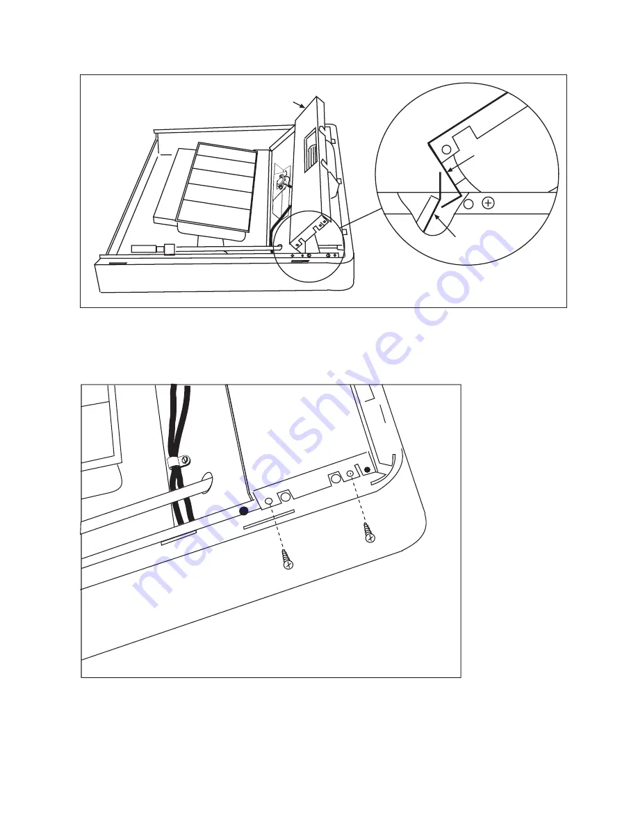
8. Carefully insert the blower assembly under the lip of the heat shield and rotate into
place.
Heat shield
Blower case
Blower assembly
9. Lower the blower into the heater and secure both ends with sheet metal screws.
Страница 1: ...t conform to local codes In the absence of local codes the installation must conform to the National Fuel Gas Code also known as NFPA 54 and ANSI Z223 1 latest edition This is a heating appliance Any safety screen or guard removed for servicing the appliance must be replaced prior to operating the appliance These instructions cover the installation of an accessory blower into a new heater prior to...
Страница 2: ...ub assembly 1 7 30512020 Open Closed Bushing 1 2 30516010 Slide Terminal Receptacle 2 8 30513010 Cord Retainer 1 3 30517010 Snap Plug Receptacle 1 9 43556010 Mounting Bracket L shaped 1 4 02315010 Sheet Metal Screw 3 8 long 9 10 43563010 Cord Set Sub assembly 1 5 02261030 Grounding Screw Green 1 11 30749000 Wire Clamp 1 6 43565090 Fan Control Switch Automatic 1 2 Lay the heater on a flat surface a...
Страница 3: ...0 3 July 09 3 Attach fan Control Bracket and feed wires through the hole Fan control bracket Terminals Sheet metal screws 4 Turn the heater over assemble the cord retainer and insert through the back of the heater ...
Страница 4: ...Bracket and attach it to the heater Plastic bushing L Bracket Sheet metal screws 6 Lay down the blower beside the heater and pass the 3 wires through the plastic bushing Secure fan control switch wires using wire clamp and screw Blower Wire Clamp L bracket Plastic bushing 3 wires from blower ...
Страница 5: ...NG SCHEMATIC DIAGRAM OPTIONAL BLOWER If any original wire as supplied with this appliance has to be replaced it must be replaced with 18 gauge 125ºC 2 64 insulation or its equivalent Caution Label all wires prior to disconnection when servicing controls Wiring errors can cause improper and dangerous operation Verify proper operation after servicing ...
Страница 6: ...ly 09 8 Carefully insert the blower assembly under the lip of the heat shield and rotate into place Heat shield Blower case Blower assembly 9 Lower the blower into the heater and secure both ends with sheet metal screws ...
Страница 7: ...latching device becomes operative If the gas control is turned to the OFF position or gas flow to the appliance is shut off DO NOT RELIGHT THE PILOT BURNER until the safety magnet is de energized approximately 60 seconds There will be an audible click when the safety magnet in the control is de energized Pilot burner can now be relit by repeating steps 3 thru 6 above HI P OFF LO Ignitor Piezo Elec...
Страница 8: ...ounded three prong receptacle The appliance when installed must be electrically grounded in accordance with local codes or in the absence of local codes with the National Electrical Code ANSI NFPA 70 latest edition DO NOT cut or remove the grounding prong from this plug For an ungrounded receptacle an adapter which has two prongs and a wire for grounding can be purchased plugged into the ungrounde...