background image

6-1) ADJUSTING THE TRIMMERS

6-1-1) Adjusting the Position of the Trimming Cam (Insert Angle of Movable Blade)

The movable blade is started by the trimmer cam in the angle it is inserted. As one of the basic trimming
functions, it arranges the upper thread tails in the needle after trimming.

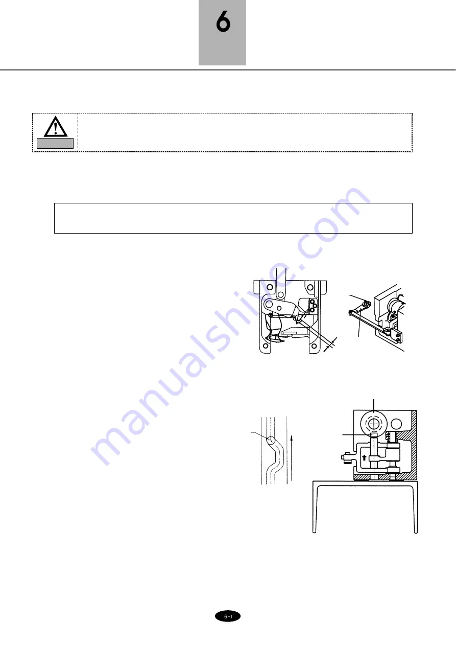
1) Adjusting the position of the movable blade

Check if the movable blade is in the correct
position. 

Cutting point of the movable blade should be
inserted 1mm at the end of the fixed blade. Incorrect
position of the movable blade can cause trimming
errors or deviation of the upper thread.

Unfasten the crank screw to adjust the location of
the movable blade (see [Fig.6-1]). 

2) Adjusting the angle of the movable blade

Unfasten two screws on the blade cam. Adjust the
upper shaft rotary angle at 290°. 

Insert the trimming cam roller into the trimming
cam. Turn the cam and when the roller aligns with
the curve of the cam, fasten the two screws back.

Run the manual handle and check if the movable
blade is well-inserted at 290°. Always check after
the adjustment.

[Fig.6-1]

WARNING

Turn OFF the main power when adjusting the machine.

MAJOR MACHINE ADJUSTMENTS

App.
1mm

Screw

Trimming
drive crank

Blade cam

Roller

Roller

Direction 
of cam
movement

[Fig.6-2]

Содержание HC Series

Страница 1: ...M MM ME E 1 11 10 01 10 03 3 USER S MANUAL S Su un nS St ta ar r C CO O L LT TD D Dual Function HC Series ...

Страница 2: ...E MACHINES FOR ANY INQUIRIES ON THE MACHINE OR THE INSTRUCTION CALL YOUR SWF DEALERSHIP 3 MAKE SURE TO PASS THIS INSTRUCTION TO YOUR NEXT WORKER 4 FOR INFORMATION RELATED TO ELECTRICITY AND ELECTRONIC PARTS X Y DRIVE CONTROL BOX OPERATION BOX PLEASE REFER TO SWF DUAL FUNCTION ELECTRICITY MANUAL 5 THIS IS DESIGNED AND MANUFACTURED AS AN INDUSTRIAL MACHINE IT SHOULD NOT BE USED FOR OTHER THAN INDUST...

Страница 3: ...8 2 7 FRAME ASSEMBLY UH1504D 45 UH1208D 45 UH1512D 45 2 9 2 7 1 TUBULAR FRAME 2 9 2 7 2 BORDER FRAME 2 10 CHAPTER 3 NAMES OF MACHINE PARTS 3 1 3 1 SWF HC UH1506D 45 3 1 CHAPTER 4 FUNCTIONS FOR BASIC MACHINE OPERATION 4 1 4 1 LAMP ON THREAD TENSION ADJUSTMENT BOARD 4 1 4 2 NEEDLE STOP CLUTCH 4 2 4 3 UPPER THREADING AND TENSION ADJUSTMENT 4 3 4 4 LOWER BOBBIN THREADING AND TENSION ADJUSTMENT 4 7 4 5...

Страница 4: ... 6 5 6 5 ADJUSTING LOW NOISE PRESSER FOOT 6 6 6 6 RELATIONSHIP BETWEEN PRESSER FOOT AND NEEDLE 6 7 6 7 CORRECT POSITION OF NEEDLE 6 8 6 8 ADJUSTING HALF TURN FILM FOR COLOR CHANGE 6 9 6 9 ENCODER ADJUSTMENT 6 9 6 10 JUMP MOTOR ADJUSTMENT 6 10 6 11 ADJUSTING DRIVER BELT TENSION 6 11 6 11 1 SPECIFICATIONS OF DRIVER BELT TENSION ADJUSTERS 6 11 6 11 2 Y AXIS TIMING BELT 6 11 6 11 3 X AXIS TIMING BELT ...

Страница 5: ...ength Place a wooden block at either side of the machine before tying the rope The angle should be 40 or less Make sure that the rope does not touch the table Make sure all persons and obstacles are out of the way of the moving equipment Fig 1 1 1 1 MACHINE DELIVERY DANGER SAFETY RULES DANGER These safety instructions MUST be observed to be safe from danger when installing delivering or repairing ...

Страница 6: ... may incur machine malfunction or breakdown Make sure to meet the following conditions 1 The foundation under the machine i e table or desk must be strong enough to support the weight of the machine approximately 1 ton 2 Air conditioning can eliminate dust and humidity that can cause pollution and corrosion of the machine Make sure your machine is regularly cleaned 3 Long exposure to direct sunlig...

Страница 7: ... in the machine Wear shoes with non slip soles 3 Clear all persons from the machine before turning on the power 4 Keep your hands or head away from the moving parts of the machine such as needle hook take up lever and pulley when the machine is in operation 5 Do not remove the safety cover on the pulley or shaft when the machine is in operation 6 Be sure the main power is turned off and the power ...

Страница 8: ...g Physical damage may be caused by winding Don t put your hands near the arrow while the main shaft is rotating Injury may be caused by moving needle Ensure that the machine is in a stop condition before changing threading or rethreading of needies or changing of needles Turn off the main power before rotating the main shaft by hand Do not remove covers during operation Turn off the main power bef...

Страница 9: ...nging of needles CAUTION Safety cover refers to all covers near the operating parts of the machine Injury may be caused by winding Be sure to turn off the power before cleaning lubricating adjusting or repairing Fire or death may be caused by high voltage electric shock Don t open the cover except for service man assigned by SWF When open the cover turn off power and wait for 6 minutes ...

Страница 10: ...usted when installing 100V 110V 120V 200V 220V 240V 2 Allowed range of voltage within 10 of the voltage set 3 Electric capacity and voltage consumption 600VA 400W 4 Insulation resistance over 10M ohms measured with 500V insulation tester CAUTION Do not let moisture drops on the machine Provide air conditioning to control humidity and to prevent dust and corrosion DANGER WARNING Properly ground the...

Страница 11: ...away from the operator s work space to prevent accident or injury If the difference in heights of the four bolts is over 10mm place spacers beneath the lower supporting bolts to make the heights even 2 The machine must be horizontally balanced on all four sides front rear right and left CAUTION The level gauge does not measure accurately on a square pipe or a table Fig 2 2 3 Using the level gauge ...

Страница 12: ...olt too high it may lift the machine 5 Using the auxiliary balance supporting bolt UH1508 45 UH1512D 45 Adjust the supporting bolt at the center of the machine after the balancing of the machine is finished When adjusting the supporting bolt turn the bolt until it touches the level base and turn an additional quarter round Fasten the supporting bolt with a nut Fig 2 5 Adjusting bolt CAUTION The us...

Страница 13: ... ASSEMBLY 1 Assembling Upper Thread Stand 2 Assembling Operation Box Thread holder Spool plate Support MC1 I O Board To Joint Board 50P MC2 I O Board To Joint Board 50P MC2 I O Board To Joint Board 68P MC1 I O Board To Joint Board 68P ...

Страница 14: ...erneath the table and the bolts to disassemble the table 2 Adjust the table support at an appropriate height and fasten the bolts Fig 2 8 Fig 2 9 Clamp Clamp Clamp Table support Table Table support bolts Bolts Table height Work type Board Tubular Cap ...

Страница 15: ...ld not be higher than the upper side of the needle plate by 0 5mm for board frame work If the height difference is over 0 5mm unfasten the table support bolts adjust the height and fasten the bolts back Clamp Clamp Clamp Table support Bolts Height difference If higher by 0 5mm Table support Bolts ...

Страница 16: ...the tubular frame Align it on the fixing position on the X frame insert the frame fixing bolt and fix Fig 2 12 Tubular frame X frame Fixing bolts Fig 2 13 Tubular round frame 3 In case using the tubular round frame CAUTION 1 When inserting the frame onto the arm of the tubular frame adjust the space between the two To adjust use the screw on the tubular frame arm ...

Страница 17: ...g 2 14 Fig 2 15 2 Adjust the table height appropriate for border frame work See 2 5 Table Assembly 3 Unfasten screws on the border frame and align the border frame in the fixing position on the X frame 4 Fix the border frame onto the X frame with a fixing bolt Tubular frame Fixing bolts Fixing bolts ...

Страница 18: ...the tubular frame in the groove of the frame connection plate and fasten the bolt CAUTION Do not install the tubular frame too close from the X frame Keep the space at around 2mm 2 Insert the frame into the tubular frame Use the screws to adjust the space Fig 2 16 Tubular frame Frame connection plate Fixing hole Fixing bolt ...

Страница 19: ...Unfasten screws on the tubular frame 2 3 and remove the frame 2 Adjust the table height at an appropriate level for border frame work See 2 5 TABLE ASSEMBLY 3 Unfasten screws on the border frame 2 3 and install the border frame in the groove of the X frame connection plate Fasten the bolt ...

Страница 20: ... Upper thread holder Head Thread tension adjustment board Sub controller X axis driving system Y axis driving system Emergency stop S B button Tubular frame Border frame Controller box Operation box Encoder Main power switch Leveling base Thread detector Emergency power switch NAMES OF MACHINE PARTS 3 1 SWF HC UH1506D 45 ...

Страница 21: ...ch off 2 Thread Break Detector Lamp Lamp on a specific head will blink when thread break is detected at the head while lamps on other heads will be turned off You cannot turn the lamp ON or OFF on the other heads using the toggle switch Fig 4 1 Thread sensor roller Toggle Switch Lamp Thread detection delete ON ON OFF OFF NOTE If you want to move the frame back for any reason when a thread break ha...

Страница 22: ...ent board This will turn off the detecting function on the head you are working with It can not detect thread break however thread break occurs to the head you are working with 4 2 NEEDLE STOP CLUTCH As illustrated in Fig 4 2 the needle bar will not move when you pull the jump clutch lever Push the level to the opposite direction of the operator to do move needle bar up and down Fig 4 2 Manual jum...

Страница 23: ...read stand Sub thread adjuster Thread tension adjustment board Thread detecting roller Take up lever spring stopper Take up spring Rotary tension disk Main thread tension adjuster Upper thread guide Thread guide upper Take up lever Thread guide middle Thread guide Upper thread holder Presser foot Needle Fig 4 3 ...

Страница 24: ...e on the axis of the thread adjustment device Wrap the thread around the detector roller one time Fig 4 5 Rotary tension disk Upper thread holder plate Wrap the thread 1 5 times around the rotary tension disk V shaped groove Thread between the upper thread holder plate Thread the thread guide of the needle and the needle Fix between the holder plate of the upper thread holding unit Threading the m...

Страница 25: ...on is too loose the upper thread will loop causing thread tangles or breaks If the tension is too tight puckering may occur as well as thread and needle breaks CAUTION If tension at the sub adjuster is too loose the detector roller may not rotate well and make wrong detections After adjusting the tension check if the upper thread tension is what can be pulled with little force of around 100 120g C...

Страница 26: ...thread tension You can increase the spring tension by turning the thread adjusting stud clockwise as shown in the figure You can decrease the tension by turning the stud counterclockwise ⓑ To adjust the stroke of the take up spring To adjust the stroke of the spring during embroidery work move the take up spring stopper to right or left as shown in Fig 4 8 Wrong Fig 4 7 Fig 4 8 Correct The take up...

Страница 27: ...g 2 Lower Thread Tension Adjustment Adjust the tension of the lower thread using the nut on the tension spring on the bobbin case Turn the nut clockwise to increase the tension and counterclockwise to decrease the tension Fig 4 9 Lower thread holder bobbin slot screw tension spring thread guide CAUTION Direction of the Bobbin Rotation Make sure that the bobbin rotates clockwise when you pull the t...

Страница 28: ...ockwise the bobbin thread gets thinner Fig 4 11 m in TIM ER START STOP max Knob Tension adjusting holder Tightening screw for the tension adjusting holder Bobbin axis Bobbin Thread tension adjusting nut Fig 4 12 Fig 4 13 80 Decrease Increase Knob 3 Adjustment of bobbin thread status The thread should be wound around the bobbin in parallel Otherwise loosen the tightening screw for the thread winder...

Страница 29: ...AND PRECAUTIONS Make sure to meet the following guidelines when using floppy disks Keep the disks away fro objects with magnetic fields such as televisions Protect the disks from excess heat humidity and direct sunlight Do not place heavy objects on the disks Do not remove the disk from the drive while formatting reading or writing the disk Do not open the cover of the disk drive Data cannot be wr...

Страница 30: ...for normal embroidery 3 Changing the Needle Make sure the needle is completely clear of the needle plate before attempting to change it If the needle is not clear of the plate manually turn the main shaft with a hand lever to put the needle in the right location for change STOP the machine before turning the shaft manually Immediately remove the lever afterward it is dangerous to operate the machi...

Страница 31: ...TION 1 For special threads such as artificial silk turn the needle slightly to the right to prevent thread breaks see Fig 4 19 CAUTION 2 If the needle is not inserted all the way to the top of the needle bar hole timing of the machine will go off causing broken needles and thread breaks Fig 4 18 Fig 4 19 Needle insert hole Front groove of the needle groove ...

Страница 32: ...uld be 0 1 0 3 mm minimum Thread skip occurs due to thread looping or inadequate balance gap between the needle and the hook The closer the hook point is to the needle the hook point will be inside the loop and threading will be more stable Fig 4 20 Fig 4 22 Hook point 0 1 0 3mm Fig 4 21 Top point of hook circumference Top edge of needle eye Needle tip a Top edge of needle eye Hook allowance gap H...

Страница 33: ...evention of looping is important for stitching Adjust the hook point as close to the needle as possible to achieve the perfect thread position If thread breaks or stitches are unstable turn the needle slightly to the right NOTE Shape of the loop varies by the type of thread or fabric Unstable shape of the loop may result in skipped stitches The following pictures show different shapes of loop form...

Страница 34: ...iming Slow Hook Timing Fig 4 26 too small too large Fig 4 27 Fig 4 28 Groove of the hook is in the A range The hook point will take up the thread when the loop is too small Stitching will be faster than the take up movement As a result the thread tension will be too loose upper thread loop will be too small and skipped stitches will occur Groove of the hook is in the B range The hook point will ta...

Страница 35: ... THREAD DETECTOR You will need to disassemble the thread break detector unit to clean Remove the cover of the thread tension adjusting plate separate the cables and unfasten the roller base joint screw The entire unit will be disassembled including the rollers and bush bearing Fig 4 29 Film Roller base Bush bearing Roller base screw Thread detector roller CAUTION Make sure to correctly place the t...

Страница 36: ...rts due to insufficient oiling and greasing CAUTION 5 2 CLEANING Safety rules must be observed during the inspection Turn OFF the main power before inspecting or cleaning of the following parts 5 MAINTENANCE AND INSPECTION CAUTION SWF is not responsible for machine damages or malfunctions caused by insufficient cleaning or oiling CAUTION 1 2 3 Reference Fig NO Important Parts for Cleaning Cleaning...

Страница 37: ... Fig 5 1 Hook Guide rail to the take up lever Movable blade Fixed blade ...

Страница 38: ...all amount of oil on the raceway Needle bar and needle bar shaft Inside the arm 3 4 times a day Once a week Once a week 4 Guide rail to the take up lever 3 oil holes on the bed cover Juncture of the movable blade and the fixed blade in the trimming unit Once a week Once in 3 days Once in 2 3 weeks Where to Oil Oiling cycle Ref Fig No CAUTION Make sure to turn the power OFF during oil supply Head A...

Страница 39: ...ON 1 Use the SWF sewing machine oil Spindle Oil or ISO standard VG18 2 Oil just enough to damp the tape in the oil tank 3 Oiling Fig 5 3 1 Inside arm a driver pin of take up lever b driver pin of presser foot c driver shaft of needle bar Once in 2 days Where to oil Oiling cycle No ...

Страница 40: ... the upper thread holder Hook gear and lower gear in the rotary hook base Once in 3 months Once in 3 months Once in 1 months Where to Grease Greasing cycle Reference Fig NO Make sure to turn OFF the main power during the grease supply CAUTION Trimming cam driver box Arm Head Fig 5 4 1 Gears in the blade cam and trimming cam box Once in 3 months 2 Color change cam color change head roller Once in 3...

Страница 41: ... axis LM guide Sub Y drive LM guide Head drive LM guide Once in 2 months Once in 2 months Once in 2 months Once in 2 months Where to Grease Greasing cycle Reference Fig NO Turn OFF the main power during the grease supply CAUTION X axis LM guide Y axis roller guide X frame Y frame Bed 2 Sub Y drive LM guide Head drive LM guide upper cover opened ...

Страница 42: ...n for inspection Belt on main shaft motor Upper Lower shaft belt X axis timing belt Y axis timing belt Inspection cycle Once in 3 months Once in 3 months Once in 3 months Once in 3 months Reference check belt tension check for belt crack check for belt wear out check for bearing damage check for wear outs of rotating sliding parts NO CAUTION Turn OFF the main power when inspecting drive belt tensi...

Страница 43: ...lade can cause trimming errors or deviation of the upper thread Unfasten the crank screw to adjust the location of the movable blade see Fig 6 1 2 Adjusting the angle of the movable blade Unfasten two screws on the blade cam Adjust the upper shaft rotary angle at 290 Insert the trimming cam roller into the trimming cam Turn the cam and when the roller aligns with the curve of the cam fasten the tw...

Страница 44: ...ion of the movable and the fixed blades after replacement or repair Fig 6 4 Movable blade Tension control screw Fixed blade Return spring unit Spring shaft screw Sensor 1mm 6 1 3 ADJUSTING THE TRIMMER RETURN SPRING 1 Function The trimmer return spring detects if the movable blade returns to the correct position after trimming If the machine operates without the blade returned to its correct positi...

Страница 45: ...d holding solenoid over the center and unscrew the lever Support the arm protection plate with a flat plate so the lever touches the flat plate Fasten the screw of the upper thread holding lever Make sure that the upper thread holding lever is touching the axis of the upper thread holding solenoid Check if the lever moves smoothly left and right when you manually operate it Install the arm protect...

Страница 46: ... position as in Fig 6 6 Adjusting the starting height Unfasten the screw on the picker stopper Adjust so that the picker softly touches the bobbin when pressed by hand Adjusting picker standby position Unfasten the screws on the picker solenoid cover Adjust the position of the solenoid cover so that the tip of the picker is around 20mm away from the bobbin Picker screw Correct position of the pick...

Страница 47: ...ws on the drive link Move the wiper lever up and down and unfasten the bracket screws so the wiper is not loaded by the upper thread holder bracket Fasten the screws back when the wiper moves smoothly After the adjustment run the color change function to check if the wiper operates well at each needle bar If trimming error or jump error occurs on a certain head during the embroidery run the wiper ...

Страница 48: ...ever driver cam Adjust the presser foot driver cam to where the reference pins freely move left and right Fix the three screws M4 L35 CAUTION 1 The assembly pin should smoothly move right and left with the three screws fastened 2 The assembly unit and the assembly pin are not for commercial sale 3 Contact your SWF dealer if you must adjust the location of the cam Fig 6 12 Reference pins 3 Hole 3 A...

Страница 49: ...essing the embroidery material before the needle pierces into the material The same is true for when the needle comes out of the material 2 When the Presser Foot is Too High Needle In Fig 6 15 shows the presser foot fails to press the work material when the needle pierces into the fabric causing an unstable needlework Needle Out Fig 6 16 shows the presser foot fails to press the work material when...

Страница 50: ...lever to set the shaft at around 130 Position the needle at the lower dead stop and check if the needle is at the center of the needle hole on the plate If the needle is not in the correct position unscrew the brackets two screws to adjust the head and the needle see Fig 6 17 Fig 6 17 L wrench Bracket screws Head Needle plate Needle plate CAUTION Check the needle position on all heads ...

Страница 51: ... performed at the upper shaft angle of 100 Manual color change at the upper shaft angles other than 100 may cause damage on the controller and the take up unit Fig 6 18 6 9 ENCODER ADJUSTMENT Adjust the encoder as below if the needle bar stops at an incorrect position Unfasten the two encoder coupling screws Turn the hand lever fix the upper shaft angle at around 98 and adjust the encoder as in Fi...

Страница 52: ...h base is in line with the center of the clutch pin and the center of the motor shaft when in standby see Fig 6 21 If not unscrew and adjust the clutch body with the jump crank roller attached to the stopper Fasten the screw back Pull the clutch lever forward and check if the clutch body and the stopper are completely attached If not adjust the stopper to be completely attached to the body Fig 6 2...

Страница 53: ...Model U 305 Series Sound Wave Belt Tension Gauge Standard Manufacturer UNITTA To adjust the tension on the Y axis timing belt unfasten the tension base screws Turn the bolts to adjust the tension Turn clockwise to increase and counterclockwise to decrease the tension CAUTION 1 Drive belt tension can be adjusted only by trained SWF engineers 2 Make sure to turn OFF the machine during the adjustment...

Страница 54: ...ound wave tension gauge Tension on the X axis timing belt should measure as below on the sound wave measurer when you pluck the middle of the belt with your finger Input data for the sound wave tension measurer Fig 6 23 Tension bolt Weight Wide Span Tension measurement 4 0 gf m 15 mm R 610 mm 19 kgf Type SWF HC UH1504D 45 3 8 gf m 35 mm R 445 mm 25 kgf SWF HC UH1506D 45 4 0 gf m 15 mm R 590 mm 19 ...

Страница 55: ...nd adjust it right and left to get the right tension Turn the idler left to increase the tension and right to decrease the tension 6 12 LAMP OPTIONAL 6 12 1 Adjusting Lamp Socket Standard lamp for SWF machines measures 580mm in length If you have to use 590mm lamp for certain purposes adjust the lamp in the following order Unfasten the three screws on the socket Push the lamp socket fully to the r...

Страница 56: ...elt Incorrect position of encoder or bad encoder Adjust belt tension change belt Check fuse in main shaft motor and change fuse Run manual color change and check if signal lamps needle set lamp needle position lamp blinks at correct needle position Adjust the half turn film Address the cause and press RESET Check if the lamp turns green Check connection of START switch Adjust belt tension Adjust e...

Страница 57: ...t lamp needle position lamp blinks at correct needle position Adjust the half turn film Set it to the correct position Adjust so take up lever is in line with other levers in stop position upper shaft angle 100 Change fuse F3 in joint board or check connection Set main shaft angle back at 100 if you manually moved it for cleaning inspection or repair Unscrew the lever and adjust so it is in line w...

Страница 58: ... X Y belt Foreign substance in X Y rail Failure of X Y driver board Heavy load on frame Inspection Repair Clean the spring and the plate or adjust the spring tension Check the plate connection and change the circuit board Change front fuse F3 in joint board Check wiring and change solenoid Check connection Change switch and circuit board Correct tape Adjust tension Clean the rail Change circuit bo...

Страница 59: ...nt dent worn Incorrect needle installation height direction etc Dirty needle adhesive etc Inspection Repair Re punch design tape Re punch after checking design Correct the stitches on operation box Change needle Change needle Re install needle Clean or change needle and hook Check design Use minimum adhesive for appliqu Reference Thread breaks ...

Страница 60: ...hreads Excessive tension stroke on take up spring Inspection Repair Change thread Change to left twisted thread Adjust tension Adjust tension and stroke Check the using thread Selecting thread soft even thickness tight left twisted Z direction left S direction right CAUTION left twist prevents unraveling in the counterclockwise rotation of the hook Reference ...

Страница 61: ...oves on the frame Inadequate height of presser foot does not press the work material Inspection Repair Remove dent or change the case Adjust space Oil the raceway of hook Adjust timing Adjust the lower dead stop Check Thread path in presser foot Around needle hole on needle plate Thread guide on the head Thread path in tension adjuster Fix the material firmly Adjust height Set it at 0 5 0 7mm for ...

Страница 62: ...st elasticity and flexibility Excessive tension or stroke on the take up lever spring Fabric moves with needle weak or damaged presser foot spring Inspection Repair Change needle Adjust installation Adjust timing Adjust the lower dead stop Use whetstone to adjust hook point or change hook Adjust thread tension For upper thread change bobbin or bobbin case Select right thread for embroidery Adjust ...

Страница 63: ...ouches the hook point Incorrect installation of needle Needle touches the needle hole on the plate Inspection Repair Adjust tension Clean main and sub tension adjusters in the thread tension adjusting plate Adjust tension Clean bobbin case and check tension on bobbin spring Change to quality thread Adjust timing Oil the raceway of hook Change needle Space the needle and the hook point Correct the ...

Страница 64: ...rimming fuse Poor connection quality of trimming solenoid Bad connection Trimming driver TR damaged Inspection Repair Adjust tension Change presser foot spring Change needle Use adequate size of needle Check and change fuse F1 in joint board Check and change solenoid and solenoid connection Check connection Change joint board SWF needle holes are 2 0mm Check fuse spec Reference Puckering Trimming ...

Страница 65: ...sensor clean around the sensor adjust location of the sensor unit Adjust insert angle of movable blade 295 Adjust picker position Check and change fuse F1 Check change solenoid and solenoid connection Check connection and change joint board Adjust upper thread tension remove dent using whetstone or sandpaper or change movable blade adjust or change bobbin case spring clean check for dent in thread...

Страница 66: ... LONG or MEDIUM length of trimmed thread in data set up set MEDIUM or SHORT length of trimmed thread in data set up if upper thread is held due to narrow velcro space in upper thread holder clean the velcro Check screws and crank driver clamp screws of the movable blade Check tension of fixed blade Change movable blade Adjust the position of movable blade Check change fuse F1 F2 F3 in joint board ...

Отзывы: