6
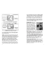
Fig 2a – AC End, 110VAC/60Hz Inverter (SUN110)
Fig 2b – AC End,
220VAC/50Hz Inverter (SUN220, “International”)
or
240VAC/60Hz Inverter (SUN240, “well pump”)
For information regarding the terminal block and/or usage other
than stand-alone, please call or have your certified electrician
call Alan at 540-234-0164.
Inverter:
The inverter features bar graph displays for AC load
(Current Output) and DC status (Volts). When fully charged,
battery voltage will be approximately 14V (see table on pg 9). At
10.7 volts, the inverter’s battery voltage bar graph will read in the
lower red zone and an audible low battery warning will sound.
To extend run time, reduce AC load if possible or connect
charging source. The SUNRNR will continue to run while
beeping until the inverter automatically shuts down for low
battery voltage at about 10.0 volts, protecting the AC loads from
under voltage and the battery from complete discharge.
If the battery nears overcharge (bar graph in upper red zone),
the inverter will beep and shut down until the charging source is
removed and the battery voltage is allowed to drop to "normal".
7
The Current Output bar graph indicates AC load being supplied
to the devices being run - green for normal operation and upper
red zone during temporary surge output. See recommended
max output per outlet in Fig 2. The overload indicator will light
when load exceeds limits and inverter will automatically shut
down. Turn devices and inverter off, reduce load, and restart.
The inverter also has a cooling fan that is thermally activated
and may be heard operating intermittently when in normal use.
If thermal limit exceeded, the over-temp indicator will light and
the inverter will shut down until cooled.
Charging via solar:
Place panel in
best direct sunlight. Plug solar
panel’s cord with small red plug into
SOLAR (right) portal on DC end
(Fig 3).
Tabs on red plugs ensure
proper orientation.
When the panel is
connected and has light, the digital
charge controller’s LED status lights
will activate as electricity flows from
the solar panel through the charge
controller to the SUNRNR battery.
LED lights on the charge controller
give a general indication of
battery status (¼-, ½-, ¾-full,
and fully-charged). The controller’s status lights and symbols
are described fully under Specifications. The controller’s digital
LCD readout displays regardless of panel connection and
indicates battery voltage when the three-position slide switch is
set to “Voltage” or incoming charge in amps when set to
“Current”. The current/amp reading should be used for directing
the solar panel to maximize charge rate. The LCD digital current
display will read over 8 amps in bright, direct sunlight using one
panel (dropping significantly as the battery approaches full
charge) and about 0.4 amps when charging through clouds.
Slide switch to OFF in middle when not in use.
Charging via wind turbine, grid, etc
: Connect energy source
at small red AUX (left) portal. This portal bypasses the solar
charge controller and will not provide power for its LED charge
indicator lights. Energy source must be pre-wired with AUX plug
and should have internal charge controller. (See Manual
Supplement.)
This portal may also be used for 12VDC, 30-amp max
output by way of an AUX plug.
Fig 3 – Charging plugs/portals

