930475 Rev. A
I X . S e t - U p , A d j u s t m e n t & U s e
31
E
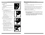
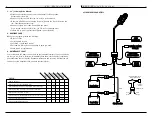
ELEVATING LEGREST (OPTIONAL)
1. Installation
To install or remove Elevating Legrest (ELR) see instruc-
tions for Swing-away Footrest installation page 28.
2. Adjustment
a. To raise legrest, lift to desired position. Legrest
will automatically lock in place.
b. To lower legrest, while seated in chair, first lift
slightly then press release lever (G) down and
lower legrest to desired position.
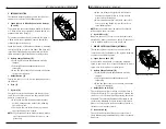
F. INTEGRAL JOYSTICK INSTALLATION
1. To Connect
a. Align beau plug (A) with its receptacle below
seat on front of power drive unit.
b. Push in firmly.
2. To Disconnect
Pull forward firmly on the beau plug (A) until it
disconnects from receptacle.
G. REMOTE JOYSTICK INSTALLATION (OPTION)
1. To Connect
a. Line up small cylindrical connector with its
receptacle on the rear of the joystick.
b. Push in firmly.
2. To disconnect
Pull back on the retaining ring (H) of the cylindrical
connector until it disconnects from the joystick box.
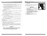
H. TO ADJUST THE HEIGHT OF THE REMOTE JOYSTICK
a. Remove the two pan-head screws (A), securing
the angle bracket mount (B).
b. Remove the Joystick from the mount by unfas-
tening the two screws (C) on the underside of
the mount.
c. Position angle bracket mount such that you
achieve the desired joystick height. Four posi-
tions are available by relocating the mount
either on the top or bottom of the mounting bar
(D) and/or by rotation of the angle
bracket mount.
I X . S e t - U p , A d j u s t m e n t & U s e
930475 Rev. A
30
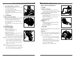
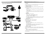
C. FOLDING BACKREST
Quickie P-220 wheelchairs are shipped with backrest in
folded position.
1. Upright Positioning
a. Lift backrest to upright position so that latch
handles (A) lock into place.
b. Backrest is ready for use.
2. Folding Backrest
a. Lift and turn backrest latch handles (A) inward
or outward.
b. Fold backrest forward.
CAUTION: Backrest latches must be locked into
place before operating wheelchair.
D. SWING-AWAY FOOTRESTS
1. Installation
a. Place swing-away pivot pin (B) into the locating
hole (C) on top of the hanger mount with the
footrest facing outward from frame.
b. Rotate the footrest inward until latch plate locks
(D) into place on locking bolt.
2. Removal
a. To remove footrest, press quick-release lever (E).
b. Rotate footrest outward and lift.
3. Height Adjustment
a. Remove both bolts (F) in the hanger frame tube.
b. Reposition footrest height.
c. Re-tighten all bolts (F).
A
new drawing
H
A
A
C
B
D
F
B
C
D
E
G

