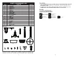
Figure 1
ASSEMBLY INSTRUCTIONS
Lantern Assembly
1.
(SEE FIGURE 1)
Screw the bulb (S) into the
lantern top (B).
2. Repeat wiht the other lantern body (A).
3. Place lantern top (B) onto lantern body (A) secure
with two small screws (L).
4. Repeat with the other lantern body (A).
5. Thread lantern body (A) onto lantern bracket (C)
and turn clockwise to tighten.
6. Repeat with the other lantern body (A).
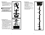
Planter Base Assembly
Note: If using ground mounting instead of
planter base mounting refer to "Ground
Mounting" on page 3.
1.
(SEE FIGURE 3)
Attach lamp post base (G) to
bottom planter (I) using hex bolts (P),
mounting plate (R), Flat washer (M), and hex
nut (N). Make sure the mounting plate, flat
washer and hex nut are secured to the hex
bolt on the underside of the bottom planter
base (I).
Figure 3
2
5
Instructions For First Time Use
Allow lantern to charge for at least 8 hours in full sunlight with the ON/OFF switch in the
OFF position. The ON/OFF switch is located under the solar panel
(See Figure 7, page 5)
. Once the
batteries are fully charged, set the ON/OFF switch to ON. If the lantern doesn't turn on after initial
charging, ensure batteries are making contact with the terminals.
Where To Place the Solar Light
Place the solar light in an area where it will receive direct sunlight for at least 8 hours per day.
The number of hours light is illuminated is directly proportional to the number of hours of sunlight
it receives. If the light is placed in a shaded area, it will not be able to fully charge and its burn time
will be limited. Do not place the light near other outdoor lighting like porch or streetlights. These
may fool the sensor and keep the light from coming on, or cause it to turn off automatically.
OPERATING SOLAR LIGHT
P
MN
G
I
Figure 7
Battery Replacement
NOTE:
The batteries in your solar lantern come
preinstalled from the factory.
1.
(SEE FIGURE 7)
Remove the screws from the
top of the lantern head (A). Battery compartment
is located under the top of the lantern head.
2. Carefully lift the lantern top off the housing.
Remove the three screws on the bottom of the
lantern top. Separate the battery compartment
from the top of the lantern head.
3. Remove old batteries.
4. Replace old batteries with new ones of the
same rating. Reference polarity direction
inside battery compartment.
5. Replace the solar panel on the housing and
secure with screws retained from step 2.
6. The rechargeable batteries need to be fully
charged before operating light assembly.
See "Operating Solar Light" to restore solar
light assembly to full operation.
Batteries
Lantern Head Top
Screws
Solar Light
Panol
R
On/Off Switch
A
L
B
S
A
C


