
© 2018 SunPower Corporation. All rights reserved. Specifications included in this manual are subject to change without notice.
Page | 2
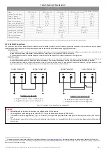
Table 1: Electrical Characteristics
1
Typical Electrical Data
at STC: 25
°
C, 1000 W/m
2
and AM 1.5
Model SPR-E-Flex-50
SPR-E-Flex-100
SPR-E-Flex-110
SPR-E-Flex-170
(4x12)
SPR-E-Flex-170 (6x8)
Nominal Power
(Pnom)
50 W
100 W
110 W
170 W
170 W
Power Tolerance
+/-5%
+6/–3%
+6/–3%
+/-3%
+/-3%
Rated Voltage (Vmpp)
17.7 V
17.1 V
18.8 V
29.9 V
29.4 V
Rated Current (Impp)
2.8 A
5.9 A
5.9 A
5.79 A
5.84 A
Open circuit voltage (Voc)
21.5 V
21.4 V
22.8 V
34.8 V
34.6 V
Short curcuit current (Isc)
3.1 A
6.3 A
6.3 A
6.10 A
6.15 A
Power Temp Coeffiecient
–0.35%/
° C –0.30%/° C –0.30%/° C
Voltage Temp Coefficient
–58.9 mV/
° C –55.8
mV/
° C –83.7
mV/
° C
Current Temp Coefficient
2.6 mA/
° C 3.5
mA/
° C 3.5
mA/
° C
Max. System Voltage
45V
Series Fuse Rating
15 A
Rated electrical characteristics are within 10% of measured values at Standard Test Conditions of: 1000W/m
2
, 25°C cell temperature and solar spectral irradiation of AM 1.5 spectrum.
4.0
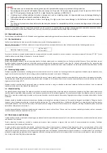
Electrical Connections
The connectors used in these panels allows for modules to be connected in series or parallel. However, connecting the panels in this manner can put the by-pass
diode in the panel and the battery at risk for damage and could create a safety issue. Please read the DANGER! note below.
Series Connection
Connecting the panels in series increases the voltage of the system, so the two panels produce double the voltage as compared to one panel. This high
voltage can cause damage to the battery and could cause a safety issues. Please read the DANGER! note below.
To connect panels in series, connect the negative (-) plug of panel #1 to the positive (+) plug of the panel #2. See Figure1 left.
Parallel Connection
Connecting the panels in parallel increases the current of the system, so the two panels produce double the current as compared to one panel. This high
current may cause damage to the battery and the by-pass diode in the junction box and cause a safety issue. Please read the DANGER! note below.
To connect panels in parallel, connect the positive (+) plug of panel #1 to the positive (+) plug panel #2 Connect the negative (-) plug of panel #1 to the
negative (-) plug of panel #2. See Figure 1 Right. In this configuration, cable adapters will be needed.
Solar Panel #1
Solar Panel #2
Solar Panel #1
Solar Panel #2
PANELS IN SERIES
2x Single Panel Open-Circuit Voltage (VoC)
1x Single Panel Open-Circuit Voltage (VoC)
PANELS IN PARALLEL
1x Single Panel Open-Circuit Voltage (VoC)
2x Single Panel Open-Circuit Voltage (VoC)
Figure 1: Schematic of two panels in series and parallel.
1
For models not shown here, please contact SunPower technical support or visit
www.sunpower.com
. Electrical parameters are measured at Standard Test Conditions
(STC). The series fuse must have an interrupting rating that is equal to or greater than the maximum fault current that the fuse is required to interrupt, including contributions
from all connected sources of energy.
DANGER!
•
Connecting panels in series will increase the voltage output of the panels.
•
DC voltages may reach levels greater than 40 V DC, in high illumination conditions (>1000 W/m
2
).
•
If attached to a low voltage battery, e.g. a 12 V battery, this high voltage could cause damage to the battery and could cause a safety
issue.
•
The charging characteristics of any battery should always be checked for compatibility with the current and voltage output of the panels
prior to use.


