
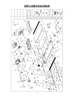
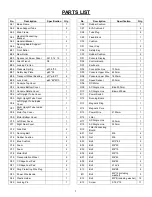
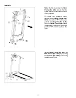
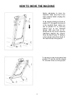
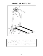

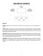
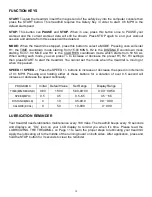

5
PARTS LIST
No.
Description
Specification
Qty.
No.
Description
Specification
Qty.
A01
Base Frame
1
C26
Rubber Cushion
1
A02
Base Support Tube
2
C27
EVA Cushion 2
2
A03
Main Frame
1
C28
Tube Plug
2
A04
Handrail Connecting
Bracket
1
C29
Fixed Block
1
A05
Handrail Bracket
2
C30
Cushion
1
A06
Running Board Support
Tube
1
C31
Inner Cap
2
B01
Front Roller
1
C32
Safety Key
1
B02
Rear Roller
1
C33
Rubber Cushion
2
B03
Spanner w/ Screw Driver
S=13, 14, 15
1
D01
Console Display
1
B04
Allen Wrench
S5
1
D02
Control Board
1
B05
Locking Pin Iron
1
D03
Keyboard
1
B06
Pressure Spring
φ10.5*30
1
D04
Connection Line
100mm
1
B07
Safety Key Plate
φ20*0.3
1
D05
Console Upper Wire
650mm
1
B08
Transport Wheel Bushing
φ11*φ8.5*7
4
D06
Console Lower Wire
1600mm
1
B09
Lock Knob
φ45*62*M10
1
D07
Speed Sensor
200mm
1
C01
Console Top Cover
1
D08
DC Motor
1
C02
Console Bottom Cover
1
D09
AC Single Line
Blue 200mm
1
C03
Console Rotate Cover
1
D10
AC Single Line
Blown 200mm
1
C04
Left Upright Tube Cover
1
D11
Power Switch
1
C05
Right Upright Tube Cover
1
D12
Running Board
1
C06
Left Upright Tube Inside
Cover
1
D13
Magnetic Ring
1
C07
Right Upright Tube Inside
Cover
1
D14
Magnetic Core
1
C08
Motor Top Cover
1
D15
Power Wire
2150mm
1
C09
Motor Bottom Cover
1
D16
Filter
1
C10
Left Rear Cover
1
D17
AC Single Line
350mm
1
C11
Right Rear Cover
1
D18
AC Single Line
350mm
1
C12
Side Rail
2
D19
Filter Connecting
Board
1
C13
Running Belt
1
E01
Nut
M6
4
C14
Rubber Cushion
4
E02
Nut
M8
4
C15
Blue Cushion
2
E03
Bolt
M10*60
2
C16
Foam
2
E04
Bolt
M8*50
2
C17
Foam
2
E05
Bolt
M8*15
2
C18
Motor Belt
1
E06
Bolt
M8*15
2
C19
Transportation Wheel
2
E07
Bolt
M6*45
1
C20
C Shape Foot Pad
2
E08
Bolt
M6*55
2
C21
C Shape Foot Pad
2
E09
Bolt
ST2.6*8
3
C22
Ring Protecting Wire Plug
2
E10
Bolt
M6*28
4
C23
Power Wire Buckle
1
E11
Bolt
M5*12(including
washer)
3
C24
Plastic Holder
1
E12
Bolt
M5*8(including washer)
12
C25
Locking Pin
1
E13
Screw
ST4.2*12
17
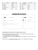
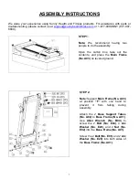
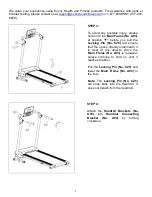
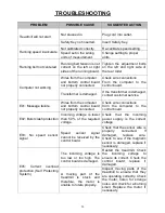
Содержание SF-T7610
Страница 5: ...4 EXPLODED DIAGRAM...


