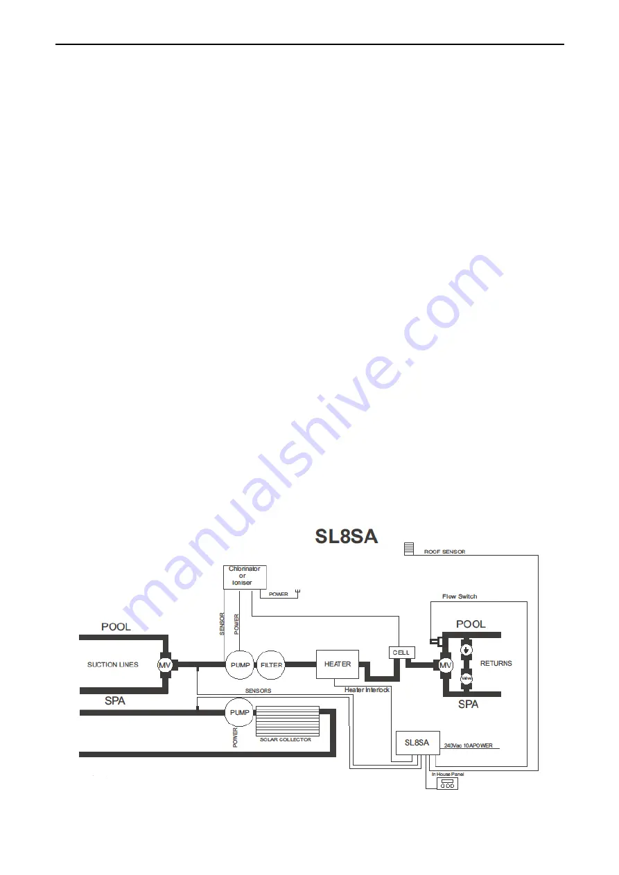
SL8SA- INSTRUCTIONS
Page 3 of 4
5) SYSTEM SETUP
Four options are available under system setup;
SET SYSTEM CLOCK / FACTORY SETTINGS / SOLAR PARAMETERS / EXIT.
EXIT
- will return you to
5) SYSTEM SETUP
with no changes.
SET SYSTEM CLOCK
– allows you to adjust calendar and time of day.
FACTORY SETTINGS
– restores all the settings to the factory default state.
SOLAR PARAMETERS
– for setting the solar start and end times.
Solar parameters;
SOLAR START TIME
SOLAR END TIME
HOUR (24H) XX
HOUR (24H) XX
The start time is the time of day ‘hour’ that the solar pump is allowed to start. The solar end time is the time of day
‘hour’ at which the pump will stop.
**Default time the solar pump is allowed to operate is from 08:00 to 19:00.
Adjust values by pressing the
Up/Down
buttons, to accept the setting press the
Enter
button.
6) SAVE & EXIT
When this menu is selected, push
Enter
to save ALL settings, the unit will return to normal operation automatically.
Note: If any of the menu items are left unattended for 3-4 mins the menu will time out and automatically save all
settings and return to operation.
The
ENTER/MANUAL
button
FOR MANUAL MODE
PRESS ENTER NOW
Pressing the
Enter
button once will display the above message for ~3 seconds, simply wait and the unit will return to
normal operation. (this can also be used to bypass the 3 minute minimum run time).
If you
Enter
is pressed for a second time within a 3 second period, the display will indicate you have entered Manual
mode, operation is the same as manual mode in the menu with the only difference being the timeout value is 4 Hours.
NOTES.
1.
If a sensor fault is detected the V7 will display which sensor and what the fault is.
2.
Should power be interrupted for any reason, the V7 will resume normal operation when power is restored, all
information will have been kept.
3.
Temperature sensors used with this unit are Digital and are accurate to 0.5 Deg. C, no calibration is required.
4.
The sensor cable with the thin trace is the positive and is usually fitted to the right hand side of the green plug,
incorrect polarity will be displayed.
5.
The heater interlock switching is used the maximum load is 5A at 32Vac max.


