background image

SunFounder uno-and-mega-kit

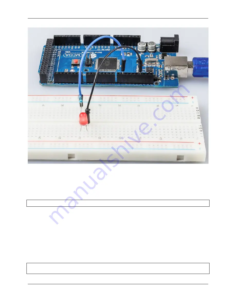
6.1.4 Code

Code Analysis

Define variables

const int

ledPin

=

9

;

//the number of the LED pin

You should define every variable before using in case of making mistakes. This line defines a constant variable

ledPin

for the pin 9. In the following code,

ledPin

stands for pin 9. You can also directly use pin 9 instead.

setup() function

A typical Arduino program consists of two subprograms:

setup()

for initialization and loop() which contains the main

body of the program.

The

setup()

function is usually used to initialize the digital pins and set them as input or output as well as the baud rate

of the serial communication.

The

loop()

function contains what the MCU will run circularly. It will not stop unless something happens like power

outages.

void

setup

()

(continues on next page)

82

Chapter 6. For Mega2560 User

Содержание R3

Страница 1: ...SunFounder uno and mega kit www sunfounder com Jan 19 2022 ...

Страница 2: ......

Страница 3: ... Display 30 2 14 4 Digit 7 Segment Display 32 2 15 LCD1602 33 2 16 Buzzer 34 2 17 DC Motor 35 2 18 Stepper Motor 37 2 19 Servo 39 2 20 Relay 40 2 21 Power Supply Module 42 2 22 Button 43 2 23 Potentiometer 45 2 24 Joystick Module 46 2 25 Photoresistor 48 2 26 Thermistor 49 2 27 Tilt Switch 50 2 28 IR Receiver Module 51 2 29 Ultrasonic Module 53 2 30 Humiture Sensor Module 54 3 Download the Code 57...

Страница 4: ...21 Simple Creation Answer Machine 191 6 22 Lesson 22 Simple Creation Small Fan 198 6 23 Lesson 23 Simple Creation Digital Dice 203 7 For Uno User 209 7 1 Lesson 1 Blinking LED 209 7 2 Lesson 2 Flowing LED Lights 217 7 3 Lesson 3 Controlling LED by Button 222 7 4 Lesson 4 Doorbell 229 7 5 Lesson 5 Tilt Switch 234 7 6 Lesson 6 Relay 237 7 7 Lesson 7 RGB LED 242 7 8 Lesson 8 Controlling an LED by Pot...

Страница 5: ...ce PictoBlox 346 8 2 Projects 348 9 FAQ 517 9 1 1 the board does not work 517 9 2 2 COM14 Access is denied 517 9 3 3 How to work in PictoBlox Stage Mode 517 9 4 4 How to work in PictoBlox Upload mode 517 10 Thank You 519 11 Copyright Notice 521 iii ...

Страница 6: ...iv ...

Страница 7: ...h building several creative projects Including a selection of the most common and useful electronic components this kit will help you control the physical world If you want to learn another projects which we don t have please feel free to send Email and we will update to our online tutorials as soon as possible any suggestions are welcomed Here is the Email cs sunfounder com CONTENTS 1 ...

Страница 8: ...SunFounder uno and mega kit 2 CONTENTS ...

Страница 9: ...CHAPTER ONE COMPONENTS LIST 3 ...

Страница 10: ...SunFounder uno and mega kit 4 Chapter 1 Components List ...

Страница 11: ...SunFounder uno and mega kit 5 ...

Страница 12: ...SunFounder uno and mega kit 6 Chapter 1 Components List ...

Страница 13: ...SunFounder uno and mega kit 7 ...

Страница 14: ...SunFounder uno and mega kit 8 Chapter 1 Components List ...

Страница 15: ...roduction to each component which contains the operating principle of the component and the corre sponding projects Basic 2 1 SunFounder R3 Board Note The SunFounder R3 board is a mainboard with almost the same functions as the Arduino Uno and the two 9 ...

Страница 16: ...set button It contains everything needed to support the microcontroller simply connect it to a computer with a USB cable or power it with a AC to DC adapter or battery to get started Technical Parameters MICROCONTROLLER ATmega328P OPERATING VOLTAGE 5V INPUT VOLTAGE RECOMMENDED 7 12V INPUT VOLTAGE LIMIT 6 20V DIGITAL I O PINS 14 0 13 of which 6 provide PWM output 3 5 6 9 11 PWM DIGITAL I O PINS 6 3...

Страница 17: ...ATmega328P EEPROM 1 KB ATmega328P CLOCK SPEED 16 MHz LED_BUILTIN 13 LENGTH 68 6 mm WIDTH 53 4 mm WEIGHT 25 g I2C Port A4 SDA A5 SCL What s More Arduino IDE Arduino Programming Language Reference Install and Introduce Arduino IDE ATmega328P Datasheet 2 2 SunFounder Mega Board 2 2 SunFounder Mega Board 11 ...

Страница 18: ...It contains everything needed to support the microcontroller simply connect it to a computer with a USB cable or power it with a AC to DC adapter or battery to get started The SunFounder Mega Board board is compatible with most shields designed for the Uno and the former boards Duemilanove or Diecimila Technical Parameters MICROCONTROLLER ATmega2560 OPERATING VOLTAGE 5V INPUT VOLTAGE RECOMMENDED 7...

Страница 19: ...n the 1970s the solderless breadboard a k a plugboard a terminal array board became available and nowadays the term breadboard is commonly used to refer to these It is used to build and test circuits quickly before finishing any circuit design And it has many holes into which components mentioned above can be inserted like ICs and resistors as well as jumper wires The breadboard allows you to plug...

Страница 20: ...t connect the slots in groups of rows or columns depending on the area The end connectors are inserted into the breadboard without soldering in the particular slots that need to be connected in the specific prototype There are three types of jumper wire Female to Female Male to Male and Male to Female The reason we call it Male to Female is because it has the outstanding tip in one end as well as ...

Страница 21: ...ce is marked on it So if you see these symbols in a circuit it stands for a resistor is the unit of resistance and the larger units include K M etc Their relationship can be shown as follows 1 M 1000 K 1 K 1000 Normally the value of resistance is marked on it When using a resistor we need to know its resistance first Here are two methods you can observe the bands on the resistor or use a multimete...

Страница 22: ...lver 0 1 2 3 4 5 6 7 8 9 0 1 0 01 The 4 and 5 band resistors are frequently used on which there are 4 and 5 chromatic bands Normally when you get a resistor you may find it hard to decide which end to start for reading the color The tip is that the gap between the 4th and 5th band will be comparatively larger 16 Chapter 2 Components Introduction ...

Страница 23: ...nd the permissible error is 1 brown Common resistor color band Resistor Color Band 10 brown black black silver brown 100 brown black black black brown 220 red red black black brown 330 orange orange black black brown 1k brown black black brown brown 2k red black black brown brown 5 1k green brown black brown brown 10k brown black black red brown 100k brown black black orange brown 1M brown black b...

Страница 24: ...les the transistor to be an amplifier From these three regions three poles are generated respectively which are base b emitter e and collector c They form two P N junctions namely the emitter junction and collection junction The direction of the arrow in the transistor circuit symbol indicates that of the emitter junction P N junction Wikipedia Based on the semiconductor type transistors can be di...

Страница 25: ...rgized But a PNP one needs a Low level signal to manage it Both types of transistor are frequently used for contactless switches just like in this experiment Put the label side facing us and the pins facing down The pins from left to right are emitter e base b and collector c 2 6 Transistor 19 ...

Страница 26: ...SunFounder uno and mega kit S8050 Transistor Datasheet S8550 Transistor Datasheet 20 Chapter 2 Components Introduction ...

Страница 27: ...SunFounder uno and mega kit 2 7 Capacitor 2 7 Capacitor 21 ...

Страница 28: ...they are widely used in direct current isolation coupling bypass filtering tuning loops energy conversion and control circuits Capacitors are divided into electrolytic capacitors solid capacitors etc According to material characteristics capacitors can be divided into aluminum electrolytic capacitors film capacitors tantalum capacitors ceramic capacitors super capacitors etc Ceramic Capacitor Wiki...

Страница 29: ...l electronics This diode is capable to conduct the values of current which changes from mA to a few kA voltages up to a few kV The designing of rectifier diodes can be done with Silicon material and they are capable of conducting high electric current values These diodes are not famous but still used Ge or gallium arsenide based semiconductor diodes Ge diodes have less allowable reversed voltage a...

Страница 30: ...nnected together the shift register is always one pulse earlier than the memory register There is a serial shift input pin Ds a serial output pin Q and an asynchronous reset button low level in the memory register The memory register outputs a Bus with a parallel 8 bit and in three states When OE is enabled low level the data in memory register is output to the bus 74HC595 Datasheet Pins of 74HC59...

Страница 31: ...p with high voltage and high current It s designed to connect to standard DTL TTL logic level and drive inductive loads such as relay coils DC Stepper Motors and power switching transistors etc DC Motors are devices that turn DC electrical energy into mechanical energy They are widely used in electrical drive for their superior speed regulation performance See the figure of pins below L293D has tw...

Страница 32: ...n electric energy into light energy via PN junctions By wavelength it can be categorized into laser diode infrared light emitting diode and visible light emitting diode which is usually known as light emitting diode LED Diode has unidirectional conductivity so the current flow will be as the arrow indicates in figure circuit symbol You can only provide the anode with a positive power and the catho...

Страница 33: ...maximum current of 20 mA so we need to connect a current limiting resistor in series The formula of the resistance value is as follows R Vsupply VD I R stands for the resistance value of the current limiting resistor Vsupply for voltage supply VD for voltage drop and I for the working current of the LED Here is the detailed introduction for the LED LED Wikipedia Example Lesson 1 Blinking LED Mega ...

Страница 34: ...e three pins and superimpose them which according to statistics can create 16 777 216 different colors RGB LEDs can be categorized into common anode and common cathode ones In this kit the latter is used The common cathode or CC means to connect the cathodes of the three LEDs After you connect it with GND and plug in the three pins the LED will flash the corresponding color Its circuit symbol is s...

Страница 35: ...re Red Green and Blue Touch its plastic shell and you will find a cut The pin closest to the cut is the first pin marked as Red then GND Green and Blue in turn Example Lesson 7 RGB LED Mega Board Project Lesson 7 RGB LED R3 Board Project 4 Colorful Balls Scratch Project 2 12 RGB LED 29 ...

Страница 36: ...re connected together forming a common pin So by forward biasing the appropriate pins of the LED segments in a particular order some segments will brighten and others stay dim thus showing the corresponding character on the display The common pin of the display generally tells its type There are two types of pin connection a pin of connected cathodes and one of connected anodes indicating Common C...

Страница 37: ...dual segment a g is energized by a ground logic 0 or LOW signal via a current limiting resistor to the cathode of the segment Example Lesson 17 7 Segment Display Mega Board Project Lesson 23 Simple Creation Digital Dice Mega Board Project Lesson 17 7 Segment Display R3 Board Project Lesson 23 Simple Creation Digital Dice R3 Board Project 2 13 7 segment Display 31 ...

Страница 38: ... of 7 segment does not show and so on the four digital display show in turn This process is very short typically 5ms and because of the optical afterglow effect and the principle of visual residue we can see four characters at the same time Display Codes To help you get to know how 7 segment displays Common Anode display Numbers we have drawn the following table Numbers are the number 0 F displaye...

Страница 39: ...lay is a kind of dot matrix module to show letters numbers and characters and so on It s composed of 5x7 or 5x11 dot matrix positions each position can display one character There s a dot pitch between two characters and a space between lines thus separating characters and lines The number 1602 means on the display 2 rows can be showed and 16 characters in each Now let s check more details 2 15 LC...

Страница 40: ...looks for instructions on what to do next R W A Read Write pin to select between reading and writing mode E An enabling pin that reads the information when High level 1 is received The instructions are run when the signal changes from High level to Low level D0 D7 to read and write data A and K Pins that control the LCD backlight Connect K to GND and A to 3 3v Open the backlight and you will see c...

Страница 41: ...en more expensive than the passive one because of multiple built in oscillating circuits The following is the electrical symbol of a buzzer It has two pins with positive and negative poles With a in the surface represents the anode and the other is the cathode You can check the pins of the buzzer the longer one is the anode and the shorter one is the cathode Please don t mix them up when connectin...

Страница 42: ...ing motion is to position the armature within the magnetic field of the permanent magnet whose field extends from the north pole to the south pole The interaction of the magnetic field and the moving charged particles the current carrying wire generates the magnetic field produces the torque that rotates the armature Current flows from the positive terminal of the battery through the circuit throu...

Страница 43: ...stepper motor In the figure in the middle of the motor is a rotor a gear shaped permanent magnet Around the rotor 0 to 5 are teeth Then more outside there are 8 magnetic poles with each two opposite ones connected by coil winding So they form four pairs from A to D which is called a phase It has four lead wires to be connected with switches SA SB SC and SD Therefore the four phases are in parallel...

Страница 44: ...ight step The step angle for the single four step and double four step are the same but the driving torque for the single four step is smaller The step angle of the eight step is half that of the single four step and double four step Thus the eight step operating mode can keep high driving torque and improve control accuracy In this experiment we let the stepper motor work in the eight step mode U...

Страница 45: ...ervo A servo is generally composed of the following parts case shaft gear system potentiometer DC motor and embed ded board It works like this The microcontroller sends out PWM signals to the servo and then the embedded board in the servo receives the signals through the signal pin and controls the motor inside to turn As a result the motor drives the gear system and then motivates the shaft after...

Страница 46: ...terclockwise from the neutral point When the pulse is wider than 1 5 ms the opposite occurs The minimal width and the maximum width of pulse that will command the servo to turn to a valid position are functions of each servo Generally the minimum pulse will be about 0 5 ms wide and the maximum pulse will be 2 5 ms wide Example Lesson 10 Servo Mega Board Project Lesson 10 Servo R3 Board Project 12 ...

Страница 47: ... armature can be moved with direct current DC as well as alternating current AC Spring When no currents flow through the coil on the electromagnet the spring pulls the armature away so the circuit cannot be completed Set of electrical contacts There are two contact points Normally open connected when the relay is activated and disconnected when it is inactive Normally close not connected when the ...

Страница 48: ... breadboard to supply power It provides a voltage of 3 3V and 5V and you can connect either via a jumper cap included Features and specifications Input voltage 6 5 12V Two Independent Channel Output voltage 5V 3 3V adjustable via jumpers 0V 3 3V and 5V configuration Output current Maximum output current 700mA Onboard berg male header for GND 5V 3 3V output ON OFF Switch available USB Type A input ...

Страница 49: ...sed as switches to connect or break circuits The following is the internal structure of a button The symbol on the right below is usually used to represent a button in circuits Since the pin 1 is connected to pin 2 and pin 3 to pin 4 when the button is pressed the 4 pins are connected thus closing the circuit 2 22 Button 43 ...

Страница 50: ...ard Project Lesson 21 Simple Creation Answer Machine Mega Board Project Lesson 3 Controlling LED by Button R3 Board Project Lesson 21 Simple Creation Answer Machine R3 Board Project 7 Doorbell Scratch Project 15 GAME Eat Apple Scratch Project 44 Chapter 2 Components Introduction ...

Страница 51: ...e resistance between the middle terminal and either one of the outer terminals varies from 0 to the maximum resistance of the pot as the knob screw or slider is moved Here is the circuit symbol of potentiometer The functions of the potentiometer in the circuit are as follows 1 Serving as a voltage divider Potentiometer is a continuously adjustable resistor When you adjust the shaft or sliding hand...

Страница 52: ...use Scratch Project 17 GAME Breakout Clone Scratch Project 2 24 Joystick Module The basic idea of a joystick is to translate the movement of a stick into electronic information that a computer can process In order to communicate a full range of motion to the computer a joystick needs to measure the stick s position on two axes the X axis left to right and the Y axis up and down Just as in basic ge...

Страница 53: ... uno and mega kit Example Lesson 16 Joystick PS2 Mega Board Project Lesson 16 Joystick PS2 R3 Board Project 14 GAME Star Crossed Scratch Project 19 GAME Kill Dragon Scratch Project Sensor 2 24 Joystick Module 47 ...

Страница 54: ... circuits and light activated and dark activated switching circuits acting as a resistance semiconductor In the dark a photoresistor can have a resistance as high as several megaohms M while in the light a photoresistor can have a resistance as low as a few hundred ohms Here is the electronic symbol of photoresistor Photoresistor Wikipedia Example Lesson 9 Photo resistor Mega Board Project Lesson ...

Страница 55: ...ses as temperature rises usually due to an increase in conduction elec trons bumped up by thermal agitation from valency band An NTC is commonly used as a temperature sensor or in series with a circuit as an inrush current limiter With PTC thermistors resistance increases as temperature rises usually due to increased thermal lattice agita tions particularly those of impurities and imperfections PT...

Страница 56: ...ormula TK 1 ln RT RN B 1 TN to get Kelvin temperature that minus 273 15 equals degree Celsius This relation is an empirical formula It is accurate only when the temperature and resistance are within the effective range Example Lesson 12 Thermistor Mega Board Project Lesson 12 Thermistor R3 Board Project 9 Low Temperature Alarm Scratch Project 2 27 Tilt Switch The tilt switch used here is a ball on...

Страница 57: ...ver Module IR Receiver Module S Signal output VCC GND An infrared receiver is a component which receives infrared signals and can independently receive infrared rays and output signals compatible with TTL level It is similar with a normal plastic packaged transistor in size and is suitable for all kinds of infrared remote control and infrared transmission 2 28 IR Receiver Module 51 ...

Страница 58: ...erface Digital Modulate Frequency 38Khz Pin Definitions 1 Output 2 Vcc 3 GND Size 23 5mm x 21 5mm Remote Control This is a Mini thin infrared wireless remote control with 21 function buttons and a transmitting distance of up to 8 meters which is suitable for operating a wide range of devices in a kid s room Size 85x39x6mm Remote control range 8 10m Battery 3V button type lithium manganese battery ...

Страница 59: ...ignal is stable within 5m and the signal is gradually weakened after 5m till the 7m position disappears The module includes ultrasonic transmitters receiver and control circuit The basic principles are as follows 1 Use an IO flip flop to process a high level signal of at least 10us 2 The module automatically sends eight 40khz and detects if there is a pulse signal return 3 If the signal returns pa...

Страница 60: ...igital temperature and humidity sensor DHT11 is a composite sensor that contains a calibrated digital signal output of temperature and humidity The technology of a dedicated digital modules collection and the temperature and humidity sensing technology are applied to ensure that the product has high reliability and excellent long term stability Only three pins are available for use VCC GND and DAT...

Страница 61: ...SunFounder uno and mega kit DHT11 Datasheet Example Lesson 15 Humiture Sensor Mega Board Project Lesson 15 Humiture Sensor R3 Board Project 2 30 Humiture Sensor Module 55 ...

Страница 62: ...SunFounder uno and mega kit 56 Chapter 2 Components Introduction ...

Страница 63: ...codes to your local folder at once please visit the link below https github com sunfounder sunfounder uno and mega kit This is a github repository which contains 3 folders the Uno Kit and Mega Kit folders contain the Arduino code and libraries datasheet and fritzing files and the Scratch folder contains the code and pictures You can download it via the Download ZIP button 57 ...

Страница 64: ...SunFounder uno and mega kit 58 Chapter 3 Download the Code ...

Страница 65: ...uino IDE upload the sketches the code files to the board and then you can see relative experimental phenomena For more information refer to http www arduino cc 4 2 Install Arduino IDE Here are the installation steps on the windows system For other systems please refer to Install Arduino IDE in different and FAQ pdf The code in this kit is written based on Arduino so you need to install the IDE fir...

Страница 66: ...here are two versions of Arduino for Windows Installer or ZIP file You re recommended to download the former 4 2 1 For Installer File Step 1 Find the exe file just downloaded Step 2 Double click the file and a window will pop up as below Click I Agree 60 Chapter 4 Install and Introduce Arduino IDE ...

Страница 67: ...under uno and mega kit Step 3 Click Next Step 4 Select the path to install By default it s set in the C disk You can click Browse and choose other paths Click OK Then click Install 4 2 Install Arduino IDE 61 ...

Страница 68: ...you can upgrade your computer 4 2 2 For ZIP File If you download the zip file before when you connect the MCU to the computer it may not be recognized Then you need to install the driver manually Take the following steps Step1 Plug in the board to the computer with a 5V USB cable After a while a prompt message of failed installation will appear Step2 Go to the Device Manager You will find under ot...

Страница 69: ...SunFounder uno and mega kit Step3 Right click on Arduino Mega 2560 and select Update Driver Software 4 2 Install Arduino IDE 63 ...

Страница 70: ...SunFounder uno and mega kit Step4 Choose the second option Browse my computer for Driver software 64 Chapter 4 Install and Introduce Arduino IDE ...

Страница 71: ...SunFounder uno and mega kit Step5 A window pops up then Click Browse Then go to the folder where you just extracted the file Go to the drivers folder and click OK Next 4 2 Install Arduino IDE 65 ...

Страница 72: ...SunFounder uno and mega kit Step6 Select Always trust software from Arduino LLC then click Install 66 Chapter 4 Install and Introduce Arduino IDE ...

Страница 73: ...SunFounder uno and mega kit It may need a sec Then the system prompts you the driver has been installed successfully So the computer can recognize the board now Click Close 4 2 Install Arduino IDE 67 ...

Страница 74: ...4 2 3 Open the Arduino Software IDE Double click the Arduino icon arduino exe created by the installation process Then the Arduino IDE will appear Let s check details of the software 68 Chapter 4 Install and Introduce Arduino IDE ...

Страница 75: ...will be prompted with errors 2 Upload Upload the code to your board When you click the button the RX and TX LEDs on the board will flicker fast and won t stop until the upload is done 3 New Create a new code editing window 4 Open Open an ino sketch 4 2 Install Arduino IDE 69 ...

Страница 76: ...some tools the most frequently used Board the board you use and Port the port your board is at Every time you want to upload the code you need to select or check them 11 Help If you re a beginner you may check the options under the menu and get the help you need including operations in IDE introduction information troubleshooting code explanation etc 12 In this message area no matter when you comp...

Страница 77: ...ncise If you don t want to use the library you can also write that function definition directly Though as a result the code will be long and inconvenient to read 5 2 Add libraries Some libraries are already built in the Arduino IDE when some others may need to be added So now let s see how to add one There are 3 methods for that 5 2 1 Method 1 Directly import the library in Arduino IDE take Dht as...

Страница 78: ...Founder Mega KitLibrary Click Open Step 3 When you see Library added to your libraries Check Include library menu it means you have added the library successfully Please use the same method to add other libraries then 72 Chapter 5 Add Libraries ...

Страница 79: ...n copy all libraries and add them at a time but the drawback is that it is difficult to find libraries Arduino Step 1 Click File Preferences and on the pop up window you can see the path of the libraries folder in the text box as shown below Step 2 Copy all Libraries in the Library folder 5 2 Add libraries 73 ...

Страница 80: ...a kit Step 3 Go to the path above and you will see there is a libraries folder click to open it Step 4 Paste all the libraries copied before to the folder Then you can see them in libraries folder 74 Chapter 5 Add Libraries ...

Страница 81: ...to install a new library into the Arduino IDE Step1 Click Sketch Include Library Manage Libraries Step2 Input a library name to search it such as dht you can choose the latest version to install Once it has finished you can close the library manager 5 2 Add libraries 75 ...

Страница 82: ...SunFounder uno and mega kit 76 Chapter 5 Add Libraries ...

Страница 83: ... 1 Blinking LED 6 1 1 Introduction You should ve learnt how to install Arduino IDE and add libraries before Now you can start with a simple experiment to learn the basic operation and code in the IDE 6 1 2 Components SunFounder Mega Board 77 ...

Страница 84: ...When the pin 9 outputs high level the current gets through the current limiting resistor to the anode of the LED And since the cathode of the LED is connected to GND the LED will light up When pin 9 outputs low level the LED goes out The schematic diagram 6 1 3 Experimental Procedures Step 1 Build the circuit the pin with a curve is the anode of the LED Then plug the board into the computer with a...

Страница 85: ...D ino code file in the path of SunFounder Mega Kit Code Lesson_1_Blinking_LED Step 3 Select the Board and Port Before uploading the code you need to select the Board and Port Click Tools Board and select Arduino Genuino Mega or Mega 2560 6 1 Lesson 1 Blinking LED 79 ...

Страница 86: ...ega kit Then select Tools Port Your port should be different from mine Step 4 Upload the sketch to the SunFounder Mega2560 board Click the Upload icon to upload the code to the control board 80 Chapter 6 For Mega2560 User ...

Страница 87: ...SunFounder uno and mega kit If Done uploading appears at the bottom of the window it means the sketch has been successfully uploaded You should now see the LED blinking 6 1 Lesson 1 Blinking LED 81 ...

Страница 88: ...irectly use pin 9 instead setup function A typical Arduino program consists of two subprograms setup for initialization and loop which contains the main body of the program The setup function is usually used to initialize the digital pins and set them as input or output as well as the baud rate of the serial communication The loop function contains what the MCU will run circularly It will not stop...

Страница 89: ...ogram repeatedly and you will see that the LED brightens for 500ms and then dims for 500ms This on off alternation will not stop until the control board runs out of energy digitWrite Pin Write a HIGH or a LOW value to a digital pin When this pin has been set as output in pinModel its voltage will be set to the corresponding value 5V or 3 3V on 3 3V boards for HIGH 0V ground for LOW Experiment Summ...

Страница 90: ...e principle of this experiment is simply to turn on eight LEDs in turn The eight LEDs are connected to pin 2 pin 9 respectively Set them as High level and the corresponding LED at the pins will light up Control the time of each LED brightening and you will see flowing LED lights The schematic diagram 84 Chapter 6 For Mega2560 User ...

Страница 91: ...SunFounder uno and mega kit 6 2 4 Experimental Procedures Step 1 Build the circuit 6 2 Lesson 2 Flowing LED Lights 85 ...

Страница 92: ... LEDs brighten one by one from the LED connected to pin 2 to that to pin 9 and then dim in turn from the LED at pin 9 to the one at pin 2 After that the LEDs will light up from the LED at pin 9 to that at pin 2 and dim from the LED at pin 2 to that at pin 9 This whole process will repeat until the circuit is power off 86 Chapter 6 For Mega2560 User ...

Страница 93: ...which accords with the condition i 9 then run the code in the curly braces set the pin2 to OUTPUT After that run i here in i i 1 the two i s are not the same but i sub now i sub before 1 Use the for statement to set pin 2 pin 9 as output respectively pinMode i OUTPUT initialize a as an output 6 2 Lesson 2 Flowing LED Lights 87 ...

Страница 94: ... high level inturn for int a 2 a 9 a digitalWrite a HIGH turn this led on delay 100 wait for 100 ms Then let the 8 LEDs go out from pin9 to pin2 in turn for int a 9 a 2 a digitalWrite a LOW turn this led on delay 100 wait for 100 ms Finally use the same way to turn on the 8 LEDs from pin9 to pin2 in turn and let them go out in turn for int a 9 a 2 a digitalWrite a HIGH turn this led on delay 100 w...

Страница 95: ...n The I O port refers to the INPUT and OUTPUT port Here the INPUT port of the Mega 2560 board is used to read the output of an external device Since the board itself has an LED connected to Pin 13 you can use this LED to do this experiment for convenience 6 3 2 Components SunFounder Mega Board Breadboard Jumper Wires Resistor Capacitor 6 3 Lesson 3 Controlling LED by Button 89 ...

Страница 96: ...end of the resistor to GND and one of the pins at the other end of the button to 5V When the button is pressed pin 12 is 5V HIGH and set pin 13 integrated with an LED as High at the same time Then release the button pin 12 changes to LOW and pin 13 is Low So we will see the LED lights up and goes out alternately as the button is pressed and released The schematic diagram 6 3 4 Experimental Procedu...

Страница 97: ...d mega kit Step 2 Open the code file Step 3 Select the Board and Port Step 4 Upload the sketch to the board Now press the button and the LED on the mega2560 board will light up 6 3 Lesson 3 Controlling LED by Button 91 ...

Страница 98: ... the button connect to pin 12 const int ledPin 13 the led connect to pin13 int buttonState 0 variable for reading the pushbutton status Connect the button to pin 12 LED has been connected to pin 13 Define a variable buttonState to restore the state of the button 92 Chapter 6 For Mega2560 User ...

Страница 99: ... the button to make the buzzer sound if buttonState HIGH digitalWrite ledPin HIGH turn the led on else digitalWrite ledPin LOW turn the led off In this part when the buttonState is High level write ledPin as High and the LED will be turned on As one end of the button has been connected to 5V and the other end to pin 12 when the button is pressed pin 12 is 5V HIGH And then determine with the if con...

Страница 100: ...SunFounder uno and mega kit 6 4 2 Components SunFounder Mega Board Breadboard Jumper Wires Resistor Capacitor Button Buzzer 94 Chapter 6 For Mega2560 User ...

Страница 101: ...SunFounder uno and mega kit 6 4 3 Schematic Diagram In this experiment we use an active buzzer The schematic diagram 6 4 Lesson 4 Doorbell 95 ...

Страница 102: ...ures Step 1 Build the circuit Long pins of buzzer is the Anode and the short pin is Cathode Step 2 Open the code file Step 3 Select the Board and Port Step 4 Upload the sketch to the board Now you should hear the buzzer beep 96 Chapter 6 For Mega2560 User ...

Страница 103: ...nst int buzzerPin 8 the buzzer connect to pin8 int buttonState 0 variable for reading the pushbutton status Connect the button to pin 2 and buzzer to pin 8 Define a variable buttonState to restore the state of the button Set the input and output status of the pins void setup continues on next page 6 4 Lesson 4 Doorbell 97 ...

Страница 104: ...make the buzzer sound if buttonState HIGH When press the button run the following code for i 0 i 50 i When i o which accords with the condition i 50 i equals to 1 here in i i 1 the two i s are not the same but i now ibefore 1 Run the code in the curly braces let the buzzer beep for 3ms and stop for 3ms Then repeat 50 times digitalWrite buzzerPin HIGH Let the buzzer beep delay 3 wait for 3ms digita...

Страница 105: ...t Switch 6 5 1 Introduction The tilt switch used here is a ball one with a metal ball inside It is used to detect inclinations of a small angle 6 5 2 Components SunFounder Mega Board Breadboard Jumper Wires Tilt Switch 6 5 Lesson 5 Tilt Switch 99 ...

Страница 106: ...SunFounder uno and mega kit 6 5 3 Schematic Diagram The schematic diagram 6 5 4 Experimental Procedures Step 1 Build the circuit 100 Chapter 6 For Mega2560 User ...

Страница 107: ... mega kit Step 2 Open the code file Step 3 Select the Board and Port Step 4 Upload the sketch to the board Now tilt the switch and the LED attached to pin 13 on Mega 2560 board will light up 6 5 Lesson 5 Tilt Switch 101 ...

Страница 108: ...alVal digitalRead 2 Read the value of pin2 if HIGH digitalVal if tilt switch is not breakover digitalWrite ledPin LOW turn the led off else if tilt switch breakover digitalWrite ledPin HIGH turn the led on The whole code are very simple one pin of the tilt switch is connected to pin2 another pin is connected to GND when tilt the switch the two pins of the switch will be connected to GND then let t...

Страница 109: ...gnal applied In other words relays provide isolation between the controller and the device as devices may work on AC as well as on DC However they receive signals from a microcontroller which works on DC hence requiring a relay to bridge the gap Relay is extremely useful when you need to control a large amount of current or voltage with small electrical signal 6 6 2 Components 6 6 Lesson 6 Relay 1...

Страница 110: ...Mega2560 board then to an NPN transistor whose collector is connected to the coil of a relay and emitter to GND connect the normally open contact of the relay to an LED and then GND Therefore when a High level signal is given to pin 8 the transistor is energized thus making the coil of the relay conductive Then its normally open contact is closed and the LED will light up When pin 8 is given a Low...

Страница 111: ...romotive force EMF will be generated at the ends of the coil with positive at the bottom and negative at the top a voltage higher than 100V This voltage plus that from the power at the transistor are big enough to burn it Therefore the freewheeling diode is extremely important in discharging this counter EMF in the direction of the arrow in the figure above so the voltage of the transistor to GND ...

Страница 112: ...d and Port Step 4 Upload the sketch to the board Now send a High level signal and the relay will close and the LED will light up send a low one and it will open and the LED will go out In addition you can hear a tick tock caused by breaking the normally close contact and closing the normally open one 106 Chapter 6 For Mega2560 User ...

Страница 113: ...onduction delay 1000 wait for a second digitalWrite relayPin LOW drive the relay is closed off delay 1000 wait for a second The code in this experiment is simple First set relayPin as HIGH level and the LED connected to the relay will light up Then set relayPin as LOW level and the LED goes out 6 6 Lesson 6 Relay 107 ...

Страница 114: ...se PWM to control an RGB LED to flash various kinds of color When different PWM values are set to the R G and B pins of the LED its brightness will be different When the three different colors are mixed we can see that the RGB LED flashes different colors 6 7 2 Components SunFounder Mega Board Breadboard Jumper Wires Resistor RGB LED 108 Chapter 6 For Mega2560 User ...

Страница 115: ...lling the brightness of the LED See the PWM description on the official website of Arduino In the graphic below the green lines represent a regular time period This duration or period is the inverse of the PWM frequency In other words with Arduino s PWM frequency at about 500Hz the green lines would measure 2 milliseconds each A call to analogWrite is on a scale of 0 255 such that analogWrite 255 ...

Страница 116: ...ent colors After connecting the pins of R G and B to a current limiting resistor connect them to the pin 9 pin 10 and pin 11 respectively The longest pin GND of the LED connects to the GND of the Mega 2560 When the three pins are given different PWM values the RGB LED will display different colors 6 7 4 Schematic Diagram 110 Chapter 6 For Mega2560 User ...

Страница 117: ... Build the circuit Step 2 Open the code file Step 3 Select the Board and Port Step 4 Upload the sketch to the board Here you should see the RGB LED flash circularly red green and blue first then red orange yellow green blue indigo and purple 6 7 Lesson 7 RGB LED 111 ...

Страница 118: ... of the RGB LED In the code it is set to flash 7 different colors You can use the paint tool on your computer to get the RGB value 1 Open the paint tool on your computer and click to Edit colors 2 Select one color then you can see the RGB value of this color Fill them in the code 112 Chapter 6 For Mega2560 User ...

Страница 119: ...urn the RGB LED green delay 1000 delay for 1 second color 0 0 255 turn the RGB LED blue delay 1000 delay for 1 second Example blended colors color 255 0 252 turn the RGB LED red delay 1000 delay for 1 second color 237 109 0 turn the RGB LED orange delay 1000 delay for 1 second color 255 215 0 turn the RGB LED yellow color function 6 7 Lesson 7 RGB LED 113 ...

Страница 120: ... redPin 0 to greenPin and 128 to bluePin Then the result is the LED flashing purple analogWrite Writes an analog value PWM wave to a pin It has nothing to do with an analog pin but is just for PWM pins You do not need to call the pinMode to set the pin as output before calling analogWrite 6 8 Lesson 8 Controlling an LED by Potentiometer 6 8 1 Introduction In this lesson let s see how to change the...

Страница 121: ...SunFounder uno and mega kit 6 8 2 Components SunFounder Mega Board Breadboard Jumper Wires LED Resistor Potentiometer 6 8 Lesson 8 Controlling an LED by Potentiometer 115 ...

Страница 122: ...eceive data via the serial port on the control board and control the board by input from the keyboard Here the Serial Monitor serves as a transfer station for communication between your computer and the Mega 2560 board First the computer transfers data to the Serial Monitor and then the data is read by the Mega 2560 board Finally the Mega 2560 will perform related operations Click the icon at the ...

Страница 123: ...s to 5V and GND respectively There fore the voltage of the potentiometer is 0 5V Spin the knob of the potentiometer and the voltage at pin A0 will change Then convert that voltage into a digital value 0 1024 with the AD converter in the control board Through programming we can use the converted digital value to control the brightness of the LED on the control board 6 8 Lesson 8 Controlling an LED ...

Страница 124: ...SunFounder uno and mega kit 6 8 4 Schematic Diagram 6 8 5 Experimental Procedures Step 1 Build the circuit 118 Chapter 6 For Mega2560 User ...

Страница 125: ...he Board and Port Step 4 Upload the sketch to the board Step5 Open the Serial Monitor Find the Serial begin code to see what baud rate is set here is 9600 Then click the top right corner icon to open the Serial Monitor 6 8 Lesson 8 Controlling an LED by Potentiometer 119 ...

Страница 126: ...set to 9600 there is no need to change the baud rate bar Spin the shaft of the potentiometer and you should see the luminance of the LED change If you want to check the corresponding value changes open the Serial Monitor and the data in the window will change with your spinning of the potentiometer knob 120 Chapter 6 For Mega2560 User ...

Страница 127: ...s between 0 and 5 volts into integer values between 0 and 1023 Print values on Serial Monitor Serial print Input print Input Serial println inputValue print inputValue Serial print Prints data to the serial port as human readable ASCII text This command can take many forms Numbers are printed using an ASCII character for each digit Floats are similarly printed as ASCII digits defaulting to two dec...

Страница 128: ...itor and analyze it Serial print Output print Output Serial println outputValue print outputValue Write the value of the potentiometer to LED analogWrite ledPin outputValue turn the LED on depending on the output value Write the output value to led Pin and you will see that the luminance of LED changes with your spinning of the potentiometer knob analog Write Writes an analog value PWM wave to a p...

Страница 129: ... intensity using a photo resistor The resistance of a photo resistor changes with incident light intensity If the light intensity gets higher the resistance decreases if it gets lower the resistance increases 6 9 2 Components SunFounder Mega Board Breadboard Jumper Wires LED Resistor Photoresistor 6 9 Lesson 9 Photo resistor 123 ...

Страница 130: ...e will use 8 LEDs to show the light intensity The higher the light intensity is the more LEDs will light up When the light intensity is high enough all the LEDs will be on When there is no light all the LEDs will go out The schematic diagram 124 Chapter 6 For Mega2560 User ...

Страница 131: ...ile Step 3 Select the Board and Port Step 4 Upload the sketch to the board Now shine some light on the photo resistor and you will see several LEDs light up Shine more light and you will see more LEDs light up When you place it in a dark environment all the LEDs will go out 6 9 Lesson 9 Photo resistor 125 ...

Страница 132: ...t int photocellPin A0 photoresistor attach to A0 int sensorValue 0 value read from the sensor int ledLevel 0 sensor value converted into LED bars The 8 LEDs are connected to pin5 pin12 in this code use a array to store the pins ledPins 0 is equal to 5 ledPins 1 to 6 and so on Set 8 pins to OUTPUT for int led 0 led NbrLEDs led continues on next page 126 Chapter 6 For Mega2560 User ...

Страница 133: ...ial port as human readable ASCII text This command can take many forms Numbers are printed using an ASCII character for each digit Floats are similarly printed as ASCII digits defaulting to two decimal places Bytes are sent as a single character Characters and strings are sent as is Serial println Thiscommand takes the same forms as Serial print but it is followed by a carriage return character AS...

Страница 134: ...is 4 then light up the ledPins 0 to ledPins 4 and go out the ledPins 5 to ledPins 7 6 10 Lesson 10 Servo 6 10 1 Introduction Servo is a type of geared motor that can only rotate 180 degrees It is controlled by sending electrical pulses from your board These pulses tell the servo what position it should move to A servo has three wires the brown wire is GND the red one is VCC and the orange one is s...

Страница 135: ...SunFounder uno and mega kit 6 10 3 Schematic Diagram The schematic diagram 6 10 Lesson 10 Servo 129 ...

Страница 136: ...C Orange to pin 9 of the control board Step 2 Open the code file Step 3 Select the Board and Port Step 4 Upload the sketch to the board Now you can see the rocker arm of the servo rotate and stop at 90 degrees 15 degrees each time And then it rotates in the opposite direction 130 Chapter 6 For Mega2560 User ...

Страница 137: ...included you can call the functions in this file later Servo is a built in library in the Arduino IDE You can find the Servo folder under the installation path C Program FilesArduinolibraries Initialize the servo void setup myservo attach 9 attachs the servo on pin 9 to servo object myservo write 0 back to 0 degrees delay 1000 wait for a second 6 10 Lesson 10 Servo 131 ...

Страница 138: ...y 15ms Use 2 for statement to write 0 180 to the servo so that you can see the servo rotate from 0 to 180 angle then turn back to 0 6 11 Lesson 11 LCD1602 6 11 1 Introduction In this lesson we will learn how to use an LCD1602 to display characters and strings LCD1602 or 1602 character type liquid crystal display is a kind of dot matrix module to show letters numbers and characters and so on It s c...

Страница 139: ...to GND and the LCD1602 to the power source Connect VO to the middle pin of the potentiometer with it you can adjust the contrast of the screen display Connect RS to D4 and R W pin to GND which means then you can write characters to the LCD1602 Connect E to pin6 and the characters displayed on the LCD1602 are controlled by D4 D7 For programming it is optimized by calling function libraries The sche...

Страница 140: ...ounder uno and mega kit 6 11 4 Experimental Procedures Step 1 Build the circuit make sure the pins are connected correctly Otherwise characters will not be displayed properly 134 Chapter 6 For Mega2560 User ...

Страница 141: ... Select the Board and Port Step 4 Upload the sketch to the board Note you may need to adjust the potentiometer on the LCD1602 until it can display clearly You should now see the characters SunFounder and hello world rolling on the LCD 6 11 Lesson 11 LCD1602 135 ...

Страница 142: ...ga kit 6 11 5 Code 6 11 6 Code Analysis Include a library include LiquidCrystal h include the library code With the LiquidCrystal h file included you can call the functions in this file later 136 Chapter 6 For Mega2560 User ...

Страница 143: ...of LCD1602 LiquidCrystal lcd 4 6 10 11 12 13 Define a variable lcd of LiquidCrystal type Here use lcd to represent LiquidCrystal in the following code The basic format of the LiquidCrysral function is LiquidCrystal rs enable d4 d5 d6 d7 You can check the LiquidCrystal cpp file for details So this line defines that pin RS is connected to pin 4 the enable pin to pin 6 and d4 d7 to pin10 13 respectiv...

Страница 144: ...nter2 Print a message to the LCD delay tim wait for 250 microseconds Similarly the code is to display the elements in array2 on the LCD Therefore you will see SunFounder scroll in the top line of the LCD move left until it disappears And then in the bottom line hello world appears scrolls to the left until it disappears 6 12 Lesson 12 Thermistor 6 12 1 Introduction We ve learnt many devices so far...

Страница 145: ...SunFounder uno and mega kit 6 12 2 Components SunFounder Mega Board Breadboard Jumper Wires Resistor Potentiometer Thermistor 6 12 Lesson 12 Thermistor 139 ...

Страница 146: ...eases with higher temperature when that of NTC decreases In this experiment we use an NTC one The schematic diagram The principle is that the resistance of the NTC thermistor changes with the temperature difference in the outer envi ronment It detects the real time temperature of the environment When the temperature gets higher the resistance of the thermistor decreases and the voltage of pin A0 i...

Страница 147: ...ate only when the temperature and resistance are within the effective range Since TK T 273 T is Celsius temperature the relation between resistance and temperature change can be transformed into this R Ro expB 1 T 273 1 To 273 B short for beta is a constant Here it is 4090 Ro is 10k ohms and To is 25 degrees Celsius The data can be found in the datasheet of thermistor Again the above relation can ...

Страница 148: ...s Step 1 Build the circuit Step 2 Open the code file Step 3 Select the Board and Port Step 4 Upload the sketch to the board Now you can see the current temperature displayed both in Celsius and Fahrenheit degrees on the LCD1602 142 Chapter 6 For Mega2560 User ...

Страница 149: ... A0 the thermistor attach to define beta 3950 the beta of the thermistor define resistance 10 the value of the pull up resistor Define the beta coefficient as 4090 which is described in the datasheet of thermistor Get the temperature void loop continues on next page 6 12 Lesson 12 Thermistor 143 ...

Страница 150: ...e temperature to the LCD lcd print tempC Print the unit of the centigrade temperature to the LCD lcd print char 223 print the unit C lcd print C note line 1 is the second row since counting begins with 0 lcd setCursor 0 1 set the cursor to column 0 line 1 lcd print Fahr lcd print tempF Print a Fahrenheit temperature to the LCD lcd print F Print the unit of the Fahrenheit temperature to the LCD del...

Страница 151: ...SunFounder uno and mega kit 6 13 2 Components SunFounder Mega Board Breadboard Jumper Wires Potentiometer Ultrasonic Module LCD1602 6 13 Lesson 13 Ultrasonic 145 ...

Страница 152: ...SunFounder uno and mega kit 6 13 3 Schematic Diagram The schematic diagram 6 13 4 Experimental Procedures Step 1 Build the circuit 146 Chapter 6 For Mega2560 User ...

Страница 153: ...n the code file Step 3 Select the Board and Port Step 4 Upload the sketch to the board Note If you receive the following error it is because you didn t add a library named NewPing please refer to Add libraries 6 13 Lesson 13 Ultrasonic 147 ...

Страница 154: ... if you use a piece of paper to approach or keep it far away from the sensor You will see the value displayed on the LCD changes which indicates the distance between the paper and the ultrasonic sensor 148 Chapter 6 For Mega2560 User ...

Страница 155: ...nsigned char type value Convert the time to distance unsigned int uS sonar ping Send ping get ping time in microseconds uS ping is used to calculate the time sent from the pulse to the reception Define a variable Us to store the received time which should be in microseconds us int distance uS US_ROUNDTRIP_CM uS US_ROUNDTRIP_CM is a formula to convert the time between ping sending and receiving int...

Страница 156: ...s a component that receives infrared signals and can independently receive infrared ray and output signals compatible with TTL level It s similar with a normal plastic packaged transistor in size and it is suitable for all kinds of infrared remote control and infrared transmission 6 14 2 Components SunFounder Mega Board Breadboard 150 Chapter 6 For Mega2560 User ...

Страница 157: ... key via a remote controller by programming When you press the key infrared rays will be emitted from the remote controller and received by the infrared receiver and the LED on the Mega 2560 board will light up The schematic diagram 6 14 4 Experimental Procedures Step 1 Build the circuit 6 14 Lesson 14 Infrared Receiver 151 ...

Страница 158: ... the LED attached to pin 13 on the Mega 2560 board will light up If you press other keys the LED will go out Note 1 There is a transparent plastic piece at the back of the remote control to cut off the power and pull it out before you use the remote control 2 Please gently press the button on the remote to avoid invalid data FFFFFFFF 152 Chapter 6 For Mega2560 User ...

Страница 159: ...IRremote h const int irReceiverPin 2 the infrared receiver attact to pin2 const int ledPin 13 built in LED IRrecv irrecv irReceiverPin Initialize the infrared receiver decode_results results The decoding result is placed in the result of the decode results structure 6 14 Lesson 14 Infrared Receiver 153 ...

Страница 160: ...al print results value HEX print the signal on serial monitor in hexadecimal Serial print bits Serial println results bits Print the data bits irrecv resume Receive next data delay 600 If the power button is pressed if results value 0xFFA25D if the power button on the remote control is pressed The 0xFFA25D is the code of the power button on the remote control if you want to define other button you...

Страница 161: ...rated digital signal output of temperature and humidity The technology of a dedicated digital modules collection and the temperature and humidity sensing technology are applied to ensure that the product has high reliability and excellent long term stability The sensor includes a resistive sense of wet component and an NTC temperature measurement device and is connected with a high performance 8 b...

Страница 162: ...SunFounder uno and mega kit 6 15 2 Components SunFounder Mega Board Breadboard Jumper Wires LCD1602 Potentiometer Humiture Sensor Module 156 Chapter 6 For Mega2560 User ...

Страница 163: ...SunFounder uno and mega kit 6 15 3 Schematic Diagram The schematic diagram 6 15 Lesson 15 Humiture Sensor 157 ...

Страница 164: ...rocedures Step 1 Build the circuit Step 2 Open the code file Step 3 Select the Board and Port Step 4 Upload the sketch to the board Now you can see the value of the current humidity and temperature displayed on the LCD 158 Chapter 6 For Mega2560 User ...

Страница 165: ...sis Initialize the humiture and LCD1602 include dht h Include the head file dht h include LiquidCrystal h LiquidCrystal lcd 4 6 10 11 12 13 initialize the LCD1602 dht DHT define DHT11_PIN 3 the humiture sensor attact to pin3 6 15 Lesson 15 Humiture Sensor 159 ...

Страница 166: ... Use the read11 function to read the value of the temperature and humidity sensor If OK is displayed on the Serial Monitor the humiture sensor is working properly read11 Return values DHTLIB_OK Indicate the humiture sensor is work well DHTLIB_ERROR_CHECKSUM DHTLIB_ERROR_TIMEOUT Display on the LCD1602 lcd setCursor 0 0 lcd print Tem lcd print DHT temperature 1 print the temperature on lcdkeep one d...

Страница 167: ...k PS2 6 16 1 Introduction A joystick is an input device consisting of a stick that pivots on a base and reports its angle or direction to the device it is controlling Joysticks are often used to control video games and robots A Joystick PS2 is used here 6 16 2 Components SunFounder Mega Board Breadboard Jumper Wires Joystick Module 6 16 Lesson 16 Joystick PS2 161 ...

Страница 168: ...presenting whether it is pressed on Z axis The module integrates power indicator and can display operation condition In this experiment we use the Mega 2560 board to detect the moving direction of the Joystick knob and pressing of the button The schematic diagram 6 16 4 Experimental Procedures Step 1 Build the circuit 162 Chapter 6 For Mega2560 User ...

Страница 169: ...ect the Board and Port Step 4 Upload the sketch to the board Now push the rocker and the coordinates of X and Y axes displayed on Serial Monitor will change accordingly press the button and the coordinate of Z 0 will also be displayed 6 16 Lesson 16 Joystick PS2 163 ...

Страница 170: ...nitor to print the value of the VRX VRY and SW pins of the joystick ps2 void loop Serial print X Serial print analogRead xPin DEC print the value of VRX in DEC Serial print Y Serial print analogRead yPin DEC print the value of VRX in DEC continues on next page 164 Chapter 6 For Mega2560 User ...

Страница 171: ...s a device that can display numerals and letters It s made up of seven LEDs connected in parallel Different letters numbers can be shown by connecting pins on the display to the power source and enabling the related pins thus turning on the corresponding LED segments In this lesson let s learn how to display specific characters on it 6 17 2 Components SunFounder Mega Board 6 17 Lesson 17 7 Segment...

Страница 172: ...s experiment connect each of pin a g of the 7 Segment Display to one 220ohm current limiting resistor respec tively and then to pin 4 11 GND connects to GND By programming we can set one or several of pin4 11 as High level to light up the corresponding LED s The schematic diagram 166 Chapter 6 For Mega2560 User ...

Страница 173: ... Procedures Step 1 Build the circuit here a common cathode 7 segment display is used The wiring between the 7 segment display and the Mega2560 board 7 Segment Mega2560 Board a 7 b 6 c 5 d 11 e 10 f 8 g 9 dp 4 GND 6 17 Lesson 17 7 Segment Display 167 ...

Страница 174: ...mega kit Step 2 Open the code file Step 3 Select the Board and Port Step 4 Upload the sketch to the board You should now see the 7 segment display from 0 to 9 and then A to F back and forth 168 Chapter 6 For Mega2560 User ...

Страница 175: ...cond digital_2 diaplay 2 to the 7 segment delay 1000 wait for a second digital_3 diaplay 3 to the 7 segment delay 1000 wait for a second digital_4 diaplay 4 to the 7 segment Calling these functions into the loop is to let the 7 Segment display 0 F The functions are shown below Take digital_2 for example Detailed analysis of digital_2 void digital_2 void diaplay 2 to the 7 segment continues on next...

Страница 176: ...amming pins connected to these segments are set High level when c and f are Low level Here we use a for statement to set these pins as High level respectively the braces after for are deleted as there is only one line Connect pin dp to pin 4 it s already defined as LOW in setup After running this part the 7 segment will display 2 Similarly the display of other characters are the same Since the let...

Страница 177: ...ve done previously Or you can connect the 74HC595 to three ports of the Mega 2560board and then the 7 segment display to the 74HC595 In this experiment we will use the latter By this way we can save five ports considering the Mega 2560 board s limited ports this is very important Now let s get started 6 18 2 Components SunFounder Mega Board Breadboard Jumper Wires Resistor 7 segment Display 74HC59...

Страница 178: ...data to the shift register through DS In the rising edge of the SHcp the data in the shift register moves successively one bit in one time i e data in Q1 moves to Q2 and so forth In the rising edge of STcp data in the shift register moves into the memory register All data will be moved to the memory register after 8 times Then the data in the memory register is output to the bus Q0 Q7 So the 16 ch...

Страница 179: ...ures Step 1 Build the circuit pay attention to the direction of the chip by the concave on it 7 Segment Display 74HC595 Mega2560 Kit a Q7 b Q6 c Q5 d Q4 e Q3 f Q2 g Q1 DP Q0 VCC 5V DS 11 CE GND ST 12 SH 8 MR 5V Q7 N C GND GND GND 6 18 Lesson 18 74HC595 173 ...

Страница 180: ...r uno and mega kit Step 2 Open the code file Step 3 Select the Board and Port Step 4 Upload the sketch to the board You should now see the 7 segment display from 0 to 9 and A to F 174 Chapter 6 For Mega2560 User ...

Страница 181: ...t be low level dim Since the segment g is connected to Q1 of the 74HC595 set both Q1 and DP the dot as low level and leave the rest pins as high level Therefore the values of Q7 Q6 Q5 Q4 Q3 Q2 Q1 Q0 are 1 1 1 1 1 1 0 0 Change the binary numbers into decimal ones 1x27 1x26 1x25 1x24 1x23 1x22 0x21 1x20 252 So that s the value for the number 0 to be displayed You can calculate other characters simil...

Страница 182: ...p will be at the rising edge At this time the data in the shift register will be moved to the memory register A byte of data will be transferred into the memory register after 8 times Then the data of memory register is output to the bus Q0 Q7 You will see a character is displayed on the 7 segment Then delay for 1000ms After that line go back to for The loop repeats until all the characters are di...

Страница 183: ...SunFounder uno and mega kit 6 19 2 Components SunFounder Mega Board Breadboard Jumper Wires Potentiometer Stepper Motor 6 19 Lesson 19 Stepper Motor 177 ...

Страница 184: ...atic diagram of the Stepper Motor Driver 6 19 4 Experimental Procedures Step 1 Build the circuit The wiring between Stepper Motor Driver board and Mega 2560 board Stepper Motor Driver Mega 2560 IN1 2 IN2 4 IN3 3 IN4 5 GND GND VCC 5v 178 Chapter 6 For Mega2560 User ...

Страница 185: ...tep 2 Open the code file Step 3 Select the Board and Port Step 4 Upload the sketch to the board Now you should see the rocker arm of the stepper motor spin clockwise and counterclockwise alternately 6 19 Lesson 19 Stepper Motor 179 ...

Страница 186: ...is Initialize the stepper include Stepper h include a head file the steps of a circle define STEPS 100 set steps and the connection with MCU Stepper stepper STEPS 2 3 4 5 available to store previous value continues on next page 180 Chapter 6 For Mega2560 User ...

Страница 187: ...ations per minute a positive number long loop function void loop get analog value int val analogRead 0 Read the value of the potentiometer current reading minus the reading of history stepper step val previous Turn the motor in val previous steps store as prevous value previous val the value of potentiometer assignment to variable previous The main program is to read the value of A0 first and then...

Страница 188: ...ple Creation Stopwatch 6 20 1 Introduction In this lesson we will use a 4 digit 7 segment display to make a stopwatch 6 20 2 Components SunFounder Mega Board Breadboard Jumper Wires Resistor 4 Digit 7 Segment Display 182 Chapter 6 For Mega2560 User ...

Страница 189: ... is used the common anode or common cathode pin is to control the digit displayed There is only one digit working However based on the principle of Persistence of Vision we can see four 7 segment displays all displaying numbers This is because the electronic scanning speed is too fast for us to notice interval The schematic diagram of the 4 digit 7 segment display is as shown below The schematic d...

Страница 190: ...ures Step 1 Build the circuit The wiring between the 4 digit 7 segment display and the Mega 2560 Board board is as shown below 4 Digit 7 Segment Display Mega 2560 Board a 2 b 3 c 4 d 5 e 6 f 7 g 8 p 9 D1 13 D2 12 D3 11 D4 10 184 Chapter 6 For Mega2560 User ...

Страница 191: ...Step 2 Open the code file Step 3 Select the Board and Port Step 4 Upload the sketch to the board Now you can see the number increases by one per second on the 4 digit 7 segment display 6 20 Lesson 20 Simple Creation Stopwatch 185 ...

Страница 192: ...op and the LEDs will be displayed as 0001 0 1 second later n increases by 1 n 2 and the display will become 0002 and then 0003 and on and on till 9999 n increases by 1 every second and the number displayed increases accordingly until n 10000 and n is 0 again Then the counting starts from 0 Initialize the timer Timer1 initialize 100000 set a timer of length 100000 microseconds or 0 1 sec or 10Hz th...

Страница 193: ...10 get the value of ten delay del delay 5ms clearLEDs clear the 7 segment display screen pickDigit 3 Light up 7 segment display d4 pickNumber n 10 Get the value of single digit delay del delay 5ms The loop function is used to let four segment display to display the single digit ten one hundred and thousand of a value Such as n 1345 1345 1000 1 1345 1000 100 3 1345 100 10 4 n 10 5 pickDigit int x f...

Страница 194: ...ts switch case controls the flow of programs by allowing programmers to specify different code that should be executed in various conditions In particular a switch statement compares the value of a variable to the values specified in case statements When a case statement is found whose value matches that of the variable the code in that case statement is run The break keyword exits the switch stat...

Страница 195: ...the high low level of LED Use digitalWrite to set a to f as high g as low Based on the pin diagram just mentioned when a to f is high and g is low the number 0 will be displayed void zero the 7 segment led display 0 digitalWrite a HIGH digitalWrite b HIGH digitalWrite c HIGH digitalWrite d HIGH digitalWrite e HIGH digitalWrite f HIGH digitalWrite g LOW clearLEDs function void clearLEDs clear the 7...

Страница 196: ... a p to LOW level let the 7 segment digital display go out add function void add Toggle LED count The original value of count is 0 count 1 keep the counting till 10 because one LED can display a maximum of 9 if count 10 If count 10 which is 1 second the following statement will be run count 0 which means count from 0 n then n 1 if n 10000 When n 10000 n 0 n restores to 0 190 Chapter 6 For Mega2560...

Страница 197: ...en apply a buzzer system in order to accurately fairly and visually determine the seat number of a responder Now the system can illustrate the accuracy and equity of the judgment by data which improves the entertainment At the same time it is more fair and just In this lesson we will use some buttons buzzers and LEDs to make a quiz buzzer system 6 21 Lesson 21 Simple Creation Answer Machine 191 ...

Страница 198: ...SunFounder uno and mega kit 6 21 2 Components 192 Chapter 6 For Mega2560 User ...

Страница 199: ...ram Button 1 2 and 3 are answer buttons and button 4 is the reset button If button 1 is pressed first the buzzer will beep the corresponding LED will light up and all the other LEDs will go out If you want to start another round press button 4 to reset The schematic diagram 6 21 Lesson 21 Simple Creation Answer Machine 193 ...

Страница 200: ...SunFounder uno and mega kit 6 21 4 Experimental Procedures Step 1 Build the circuit 194 Chapter 6 For Mega2560 User ...

Страница 201: ...t Step 4 Upload the sketch to the board Now first press button 4 to start If you press button 1 first you will see the corresponding LED light up and the buzzer will beep Then press button 4 again to reset before you press other buttons 6 21 Lesson 21 Simple Creation Answer Machine 195 ...

Страница 202: ...ing buttons If one of the buttons is detected to be pressed the buzzer beeps and lights the corresponding LED until button 4 is pressed again loop function b4State digitalRead button4 when button4 pressed if b4State 0 if b4State 0 confirm that the button4 is pressed One pin of the button is connected to pin 9 the other pin is connected to GND and when the button is pressed pin 9 is pulled low flag...

Страница 203: ...button3 If the button1 press the first if b1State 0 flag 0 digitalWrite LED4 LOW Alarm buzzer sound digitalWrite LED1 HIGH turn the LED1 on only digitalWrite LED2 LOW digitalWrite LED3 LOW while digitalRead button4 detect the button4 if pressed out of the while loop Alarm function void Alarm for int i 0 i 100 i digitalWrite buzzerPin HIGH the buzzer sound delay 2 continues on next page 6 21 Lesson...

Страница 204: ...ction is to set the buzzer to beep 6 22 Lesson 22 Simple Creation Small Fan 6 22 1 Introduction In this experiment we will learn how to control the direction and speed of a small sized DC motor by a driver chip L293D Making simple experiments we will just make the motor rotate left and right and accelerate or decelerate automatically 198 Chapter 6 For Mega2560 User ...

Страница 205: ...SunFounder uno and mega kit 6 22 2 Components SunFounder Mega Board Breadboard Jumper Wires Resistor Capacitor Button L293D DC Motor 6 22 Lesson 22 Simple Creation Small Fan 199 ...

Страница 206: ...Enable pin 1 2EN of the L293D are connected to 5V already so L293D is always in the working state Connect pin 1A and 2A to pin 9 and 10 of the control board respectively The two pins of the motor are connected to pin 1Y and 2Y respectively When pin 10 is set as High level and pin 9 as Low the motor will start to rotate towards one direction When the pin 10 is Low and pin 9 is High it rotates in th...

Страница 207: ...tep 1 Build the circuit Step 2 Open the code file Step 3 Select the Board and Port Step 4 Upload the sketch to the board The blade of the DC motor will begin rotating left and right in a speed that varies accordingly 6 22 Lesson 22 Simple Creation Small Fan 201 ...

Страница 208: ...es The fourth if statement is used to record the number of button presses adding 1 to stat for each press The fifth if statement is used to determine if the number of button presses is greater than 4 If so stat is cleared to zero switch statement switch stat case 1 clockwise rank1 When stat 1 set the rotate speed of the motor as rank1 150 break case 2 clockwise rank2 When stat 2 set the rotate spe...

Страница 209: ... 200 If stat 1 let the fan rotate at speed rank3 250 If stat 0 let the fan rotate at speed 0 clockwise function void clockwise int Speed analogWrite motorIn1 0 analogWrite motorIn2 Speed This function sets the speed of the motor write Speed to pin 9 and 0 to pin 10 The motor rotates in a certain direction with the value of Speed 6 22 6 Experiment Summary In this experiment you can also control the...

Страница 210: ...SunFounder uno and mega kit 6 23 2 Components SunFounder Mega Board Breadboard Jumper Wires Resistor 204 Chapter 6 For Mega2560 User ...

Страница 211: ...ea behind a digital dice is very simple a 7 segment display circularly jumps from 1 to 7 rapidly When the button is pressed the jumping will slow down until it stops on a number When the button is pressed again the process will repeat The schematic diagram 6 23 Lesson 23 Simple Creation Digital Dice 205 ...

Страница 212: ...e Step 3 Select the Board and Port Step 4 Upload the sketch to the board You can now see the 7 segment display jump between numbers from 1 to 6 Press the button and the jumping will slow down until it stops three seconds later Press the button again and the process will repeat 206 Chapter 6 For Mega2560 User ...

Страница 213: ...tial random number is generated from A0 and the range for the random numbers is 0 1023 Digital Dice void loop int stat digitalRead keyIn store value read from keyIn if stat HIGH check if the pushbutton is pressed If yes the corresponding pin is high level num num adds 1 if num 1 num 0 6 23 Lesson 23 Simple Creation Digital Dice 207 ...

Страница 214: ...check if the pushbutton is pressed If yes run the code below num num 1 2 digitalWrite ledPin HIGH turn on the led delay 100 digitalWrite ledPin LOW turn off the led delay 100 if num 1 clear the num num 0 show random numbers at 100 microseconds intervals If the button has not been pressed randNumber random 1 7 showNum randNumber delay 100 showNum function void showNum int num digitalWrite latchPin ...

Страница 215: ...NO USER 7 1 Lesson 1 Blinking LED 7 1 1 Introduction You should ve learnt how to install Arduino IDE and add libraries before Now you can start with a simple experiment to learn the basic operation and code in the IDE 209 ...

Страница 216: ... of the Uno and the other end to the anode the long pin of the LED and the cathode the short pin of the LED to GND When the pin 9 outputs high level the current gets through the current limiting resistor to the anode of the LED And since the cathode of the LED is connected to GND the LED will light up When pin 9 outputs low level the LED goes out 210 Chapter 7 For Uno User ...

Страница 217: ...der uno and mega kit 7 1 4 Experimental Procedures Step 1 Build the circuit the pin with a curve is the anode of the LED Then plug the board into the computer with a 5V USB cable 7 1 Lesson 1 Blinking LED 211 ...

Страница 218: ...SunFounder uno and mega kit 212 Chapter 7 For Uno User ...

Страница 219: ...deLes son_3_Blinking_LED Step 3 Select the Board and Port Before uploading the code you need to select the Board and Port Click Tools Board and select Arduino Genuino Uno Then select Tools Port Your port should be different from mine Step 4 Upload the sketch to the SunFounder Uno board 7 1 Lesson 1 Blinking LED 213 ...

Страница 220: ...Click the Upload icon to upload the code to the control board If Done uploading appears at the bottom of the window it means the sketch has been successfully uploaded You should now see the LED blinking 214 Chapter 7 For Uno User ...

Страница 221: ...SunFounder uno and mega kit 7 1 Lesson 1 Blinking LED 215 ...

Страница 222: ...n here sets the ledPin as OUTPUT pinMode Pin Configures the specified pin to behave either as an input or an output The void before the setup means that this function will not return a value Even when no pins need to be initialized you still need this function Otherwise there will be errors in compiling loop function void loop digitalWrite ledPin HIGH turn the LED on delay 500 wait for half a seco...

Страница 223: ...e it to delay 250 and you will find that the LED blinks more quickly 7 2 Lesson 2 Flowing LED Lights 7 2 1 Introduction In this lesson we will conduct a simple yet interesting experiment using LEDs to create flowing LED lights As the name suggests these eight LEDs in a row successively light up and dim one after another just like flowing water 7 2 2 Components SunFounder R3 Board Breadboard Jumper...

Страница 224: ...ed to pin 2 pin 9 respectively Set them as High level and the corresponding LED at the pins will light up Control the time of each LED brightening and you will see flowing LED lights 7 2 4 Experimental Procedures Step 1 Build the circuit Step 2 Open the code file Step 3 Select the Board and Port Step 4 Upload the sketch to the board 218 Chapter 7 For Uno User ...

Страница 225: ... pin 2 to that to pin 9 and then dim in turn from the LED at pin 9 to the one at pin 2 After that the LEDs will light up from the LED at pin 9 to that at pin 2 and dim from the LED at pin 2 to that at pin 9 This whole process will repeat until the circuit is power off 7 2 Lesson 2 Flowing LED Lights 219 ...

Страница 226: ...2 i 9 i 8 LEDs are connect to pin2 pin9 When i 2 which accords with the condition i 9 then run the code in the curly braces set the pin2 to OUTPUT After that run i here in i i 1 the two i s are not the same but i sub now i sub before 1 continues on next page 220 Chapter 7 For Uno User ...

Страница 227: ...he condition is tested again When the condition becomes false the loop ends Set flowing led lights Use the for statement to set pin2 pin9 to a high level inturn for int a 2 a 9 a digitalWrite a HIGH turn this led on delay 100 wait for 100 ms Then let the 8 LEDs go out from pin9 to pin2 in turn for int a 9 a 2 a digitalWrite a LOW turn this led on delay 100 wait for 100 ms Finally use the same way ...

Страница 228: ...code 7 3 Lesson 3 Controlling LED by Button 7 3 1 Introduction In this experiment we will learn how to turn on off an LED by using an I O port and a button The I O port refers to the INPUT and OUTPUT port Here the INPUT port of the Uno board is used to read the output of an external device Since the board itself has an LED connected to Pin 13 you can use this LED to do this experiment for convenie...

Страница 229: ...SunFounder uno and mega kit 7 3 2 Components SunFounder R3 Board Breadboard Jumper Wires Resistor Capacitor Button 7 3 Lesson 3 Controlling LED by Button 223 ...

Страница 230: ...the other end of the resistor to GND and one of the pins at the other end of the button to 5V When the button is pressed pin 12 is 5V HIGH and set pin 13 integrated with an LED as High at the same time Then release the button pin 12 changes to LOW and pin 13 is Low So we will see the LED lights up and goes out alternately as the button is pressed and released 7 3 4 Experimental Procedures Step 1 B...

Страница 231: ...SunFounder uno and mega kit 7 3 Lesson 3 Controlling LED by Button 225 ...

Страница 232: ...der uno and mega kit Step 2 Open the code file Step 3 Select the Board and Port Step 4 Upload the sketch to the board Now press the button and the LED on the Uno board will light up 226 Chapter 7 For Uno User ...

Страница 233: ...SunFounder uno and mega kit 7 3 Lesson 3 Controlling LED by Button 227 ...

Страница 234: ...set LedPin as OUTPUT Read the status of the button buttonState digitalRead buttonPin buttonPin Pin12 is a digital pin here is to read the value of the button and store it in buttonState digitalRead Pin Reads the value from a specified digital pin either HIGH or LOW Press the button to make the buzzer sound if buttonState HIGH digitalWrite ledPin HIGH turn the led on else digitalWrite ledPin LOW tu...

Страница 235: ... released the else the LED lights up digitalWrite ledPin HIGH You only need to replace the code in if with those in else 7 4 Lesson 4 Doorbell 7 4 1 Introduction A buzzer is a great tool in your experiments whenever you want to make some sounds In this lesson we will learn how to drive an active buzzer to build a simple doorbell 7 4 2 Components SunFounder R3 Board 7 4 Lesson 4 Doorbell 229 ...

Страница 236: ...it Breadboard Jumper Wires Resistor Capacitor Button Buzzer 7 4 3 Schematic Diagram 7 4 4 Experimental Procedures Step 1 Build the circuit Long pins of buzzer is the Anode and the short pin is Cathode 230 Chapter 7 For Uno User ...

Страница 237: ...SunFounder uno and mega kit 7 4 Lesson 4 Doorbell 231 ...

Страница 238: ...SunFounder uno and mega kit Step 2 Open the code file Step 3 Select the Board and Port Step 4 Upload the sketch to the board Now you should hear the buzzer beep 232 Chapter 7 For Uno User ...

Страница 239: ...in as OUTPUT Read the status of the button buttonState digitalRead buttonPin buttonPin Pin2 is a digital pin here is to read the value of the button and store it in buttonState digitalRead Pin Reads the value from a specified digital pin either HIGH or LOW Press the button to make the buzzer sound if buttonState HIGH When press the button run the following code for i 0 i 50 i When i o which accord...

Страница 240: ... the buttonState is High level then let the buzzer beeping in different frequency which can simulate the doorbell 7 5 Lesson 5 Tilt Switch 7 5 1 Introduction The tilt switch used here is a ball one with a metal ball inside It is used to detect inclinations of a small angle 7 5 2 Components SunFounder R3 Board Breadboard Jumper Wires Tilt Switch 234 Chapter 7 For Uno User ...

Страница 241: ...5 4 Experimental Procedures Step 1 Build the circuit Step 2 Open the code file Step 3 Select the Board and Port Step 4 Upload the sketch to the board Now tilt the switch and the LED attached to pin 13 on Uno board will light up 7 5 Lesson 5 Tilt Switch 235 ...

Страница 242: ...ed attach to void setup pinMode ledPin OUTPUT initialize the ledPin as an output pinMode 2 INPUT set pin2 as INPUT digitalWrite 2 HIGH set pin2 as HIGH void loop int digitalVal digitalRead 2 Read the value of pin2 if HIGH digitalVal if tilt switch is not breakover continues on next page 236 Chapter 7 For Uno User ...

Страница 243: ...e pin13 lights up 7 6 Lesson 6 Relay 7 6 1 Introduction As we may know relay is a device which is used to provide connection between two or more points or devices in response to the input signal applied In other words relays provide isolation between the controller and the device as devices may work on AC as well as on DC However they receive signals from a micro controller which works on DC hence...

Страница 244: ...SunFounder uno and mega kit 7 6 2 Components SunFounder R3 Board Breadboard Jumper Wires Resistor Relay 238 Chapter 7 For Uno User ...

Страница 245: ...s from High 5V to Low 0V the transistor changes from saturation three working conditions amplification saturation and cut off to cut off the current in the coil suddenly has no way to flow through At this moment without the freewheeling diode a counter electromotive force EMF will be generated at the ends of the coil with positive at the bottom and negative at the top a voltage higher than 100V Th...

Страница 246: ...SunFounder uno and mega kit Step 2 Open the code file Step 3 Select the Board and Port Step 4 Upload the sketch to the board 240 Chapter 7 For Uno User ...

Страница 247: ...ignal and the relay will close and the LED will light up send a low one and it will open and the LED will go out In addition you can hear a tick tock caused by breaking the normally close contact and closing the normally open one 7 6 Lesson 6 Relay 241 ...

Страница 248: ... the LED connected to the relay will light up Then set relayPin as LOW level and the LED goes out 7 7 Lesson 7 RGB LED 7 7 1 Introduction Previously we ve used the digital pin to control an LED brighten and dim In this lesson we will use PWM to control an RGB LED to flash various kinds of color When different PWM values are set to the R G and B pins of the LED its brightness will be different When...

Страница 249: ...SunFounder uno and mega kit 7 7 2 Components SunFounder R3 Board Breadboard Jumper Wires Resistor RGB LED 7 7 Lesson 7 RGB LED 243 ...

Страница 250: ...e signal is a steady voltage between 0 and 5V controlling the brightness of the LED See the PWM description on the official website of Arduino In the graphic below the green lines represent a regular time period This duration or period is the inverse of the PWM frequency In other words with Arduino s PWM frequency at about 500Hz the green lines would measure 2 milliseconds each A call to analogWri...

Страница 251: ...hree pins of the RGB LED to make it display different colors After connecting the pins of R G and B to a current limiting resistor connect them to the pin 9 pin 10 and pin 11 respectively The longest pin GND of the LED connects to the GND of the Uno When the three pins are given different PWM values the RGB LED will display different colors 7 7 5 Experimental Procedures Step 1 Build the circuit 7 ...

Страница 252: ...tep 2 Open the code file Step 3 Select the Board and Port Step 4 Upload the sketch to the board Here you should see the RGB LED flash circularly red green and blue first then red orange yellow green blue 246 Chapter 7 For Uno User ...

Страница 253: ...SunFounder uno and mega kit indigo and purple 7 7 Lesson 7 RGB LED 247 ...

Страница 254: ... your computer to get the RGB value 1 Open the paint tool on your computer and click to Edit colors 2 Select one color then you can see the RGB value of this color Fill them in the code void loop run over and over again Basic colors color 255 0 0 turn the RGB LED red delay 1000 delay for 1 second color 0 255 0 turn the RGB LED green delay 1000 delay for 1 second continues on next page 248 Chapter ...

Страница 255: ...nsigned char blue the color generating function analogWrite redPin red analogWrite greenPin green analogWrite bluePin blue Define three unsigned char variables red green and blue Write their values to redPin greenPin and bluePin For example color 128 0 128 is to write 128 to redPin 0 to greenPin and 128 to bluePin Then the result is the LED flashing purple analogWrite Writes an analog value PWM wa...

Страница 256: ... 1 Introduction In this lesson let s see how to change the luminance of an LED by a potentiometer and receive the data of the potentiometer in Serial Monitor to see its value change 7 8 2 Components SunFounder R3 Board Breadboard Jumper Wires LED Resistor 250 Chapter 7 For Uno User ...

Страница 257: ...d receive data via the serial port on the control board and control the board by input from the keyboard Here the Serial Monitor serves as a transfer station for communication between your computer and the Uno board First the computer transfers data to the Serial Monitor and then the data is read by the Uno board Finally the Uno will perform related operations Click the icon at the top right corne...

Страница 258: ... A0 and the other two pins to 5V and GND respectively There fore the voltage of the potentiometer is 0 5V Spin the knob of the potentiometer and the voltage at pin A0 will change Then convert that voltage into a digital value 0 1024 with the AD converter in the control board Through programming we can use the converted digital value to control the brightness of the LED on the control board 252 Cha...

Страница 259: ...SunFounder uno and mega kit 7 8 5 Experimental Procedures Step 1 Build the circuit 7 8 Lesson 8 Controlling an LED by Potentiometer 253 ...

Страница 260: ...SunFounder uno and mega kit 254 Chapter 7 For Uno User ...

Страница 261: ...rial Monitor Step 6 Set the baud rate to 9600 The default baud rate for serial monitors is 9600 and if the code is also set to 9600 there is no need to change the baud rate bar Spin the shaft of the potentiometer and you should see the luminance of the LED change If you want to check the corresponding value changes open the Serial Monitor and the data in the window will change with your spinning o...

Страница 262: ...SunFounder uno and mega kit 256 Chapter 7 For Uno User ...

Страница 263: ... n Map the values outputValue map inputValue 0 1023 0 255 Convert from 0 1023 proportional to the number of a number of from 0 to 255 map value fromLow fromHigh toLow toHigh re maps a number from one range to another That is a value of Fromm would get mapped to one of to Low and a value of from High to one of thigh values in between to values in between etc As the range of led Pin pin 9 is 0 255 w...

Страница 264: ... below Have a try inputValue analogRead analogPin digitalWrite ledPin HIGH delay inputValue digitalWrite ledPin LOW delay inputValue 7 9 Lesson 9 Photo resistor 7 9 1 Introduction In this lesson you will learn to how to measure light intensity using a photo resistor The resistance of a photo resistor changes with incident light intensity If the light intensity gets higher the resistance decreases ...

Страница 265: ...SunFounder uno and mega kit 7 9 2 Components SunFounder R3 Board Breadboard Jumper Wires LED Resistor Photoresistor 7 9 Lesson 9 Photo resistor 259 ...

Страница 266: ...SunFounder uno and mega kit 7 9 3 Schematic Diagram 7 9 4 Experimental Procedures Step 1 Build the circuit 260 Chapter 7 For Uno User ...

Страница 267: ... and Port Step 4 Upload the sketch to the board Now shine some light on the photo resistor and you will see several LEDs light up Shine more light and you will see more LEDs light up When you place it in a dark environment all the LEDs will go out 7 9 Lesson 9 Photo resistor 261 ...

Страница 268: ...7 9 6 Code Analysis Set the variables const int NbrLEDs 8 8 leds const int ledPins 2 3 4 5 6 7 8 9 8 leds attach to pin 5 12 respectively const int photocellPin A0 photoresistor attach to A0 continues on next page 262 Chapter 7 For Uno User ...

Страница 269: ...3V into integer values between 0 and 1023 Serial print SensorValue Serial println sensorValue Print the analog value of the photoresistor Use the Serial print function to print the analog value of the photoresistor You can see them on the Serial Monitor Serial print Prints data to the serial port as human readable ASCII text This command can take many forms Numbers are printed using an ASCII chara...

Страница 270: ... led HIGH turn on pins less than the level else digitalWrite ledPins led LOW turn off pins higher than Light up the corresponding LEDs Such as when the ledLevel is 4 then light up the ledPins 0 to ledPins 4 and go out the ledPins 5 to ledPins 7 7 10 Lesson 10 Servo 7 10 1 Introduction Servo is a type of geared motor that can only rotate 180 degrees It is controlled by sending electrical pulses fro...

Страница 271: ...SunFounder uno and mega kit 7 10 2 Components SunFounder R3 Board Breadboard Jumper Wires Servo 7 10 3 Schematic Diagram 7 10 Lesson 10 Servo 265 ...

Страница 272: ...VCC Orange to pin 9 of the control board Step 2 Open the code file Step 3 Select the Board and Port Step 4 Upload the sketch to the board Now you can see the rocker arm of the servo rotate and stop at 90 degrees 15 degrees each time And then it rotates in the opposite direction 266 Chapter 7 For Uno User ...

Страница 273: ...u can call the functions in this file later Servo is a built in library in the Arduino IDE You can find the Servo folder under the installation path C Program FilesArduinolibraries Initialize the servo void setup myservo attach 9 attachs the servo on pin 9 to servo object myservo write 0 back to 0 degrees delay 1000 wait for a second continues on next page 7 10 Lesson 10 Servo 267 ...

Страница 274: ...rvo delay 15 delay 15ms Use 2 for statement to write 0 180 to the servo so that you can see the servo rotate from 0 to 180 angle then turn back to 0 7 11 Lesson 11 LCD1602 7 11 1 Introduction In this lesson we will learn how to use an LCD1602 to display characters and strings LCD1602 or 1602 character type liquid crystal display is a kind of dot matrix module to show letters numbers and characters...

Страница 275: ...nnect VSS to GND and the LCD1602 to the power source Connect VO to the middle pin of the potentiometer with it you can adjust the contrast of the screen display Connect RS to D4 and R W pin to GND which means then you can write characters to the LCD1602 Connect E to pin6 and the characters displayed on the LCD1602 are controlled by D4 D7 For programming it is optimized by calling function librarie...

Страница 276: ...Founder uno and mega kit 7 11 4 Experimental Procedures Step 1 Build the circuit Step 2 Open the code file Step 3 Select the Board and Port Step 4 Upload the sketch to the board 270 Chapter 7 For Uno User ...

Страница 277: ...uno and mega kit Note you may need to adjust the potentiometer on the LCD1602 until it can display clearly You should now see the characters SunFounder and hello world rolling on the LCD 7 11 Lesson 11 LCD1602 271 ...

Страница 278: ...ystal h include the library code With the LiquidCrystal h file included you can call the functions in this file later LiquidCrystal is a built in library in the Arduino IDE You can find the LiquidCrystal folder under the installation path C Program FilesArduinolibraries 272 Chapter 7 For Uno User ...

Страница 279: ...e Define the pins of LCD1602 LiquidCrystal lcd 4 6 10 11 12 13 Define a variable lcd of LiquidCrystal type Here use lcd to represent LiquidCrystal in the following code The basic format of the LiquidCrysral function is LiquidCrystal rs enable d4 d5 d6 d7 You can check the LiquidCrystal cpp file for details So this line defines that pin RS is connected to pin 4 the enable pin to pin 6 and d4 d7 to ...

Страница 280: ...ositionCounter2 lcd scrollDisplayLeft Scrolls the contents of the display one space to the left lcd print array2 positionCounter2 Print a message to the LCD delay tim wait for 250 microseconds Similarly the code is to display the elements in array2 on the LCD Therefore you will see SunFounder scroll in the top line of the LCD move left until it disappears And then in the bottom line hello world ap...

Страница 281: ...SunFounder uno and mega kit 7 12 2 Components SunFounder R3 Board Breadboard Jumper Wires Resistor Potentiometer Thermistor LCD1602 7 12 Lesson 12 Thermistor 275 ...

Страница 282: ...red under 25 degree Celsius Here is the relation between the resistance and temperature change RT RN expB 1 TK 1 TN RT resistance of the NTC thermistor when the temperature is TK RN resistance of the NTC thermistor under the rated temperature which is TN TK is a Kelvin temperature and the unit is K TN is a rated Kelvin temperature the unit is K also And beta here is the material constant of NTC th...

Страница 283: ...0 with this formula V 10k x 5 R 10K So this relation can be formed R 5 x 10k V 10k The voltage of A0 is transformed via A D adaptor into a digital number a a V x 1024 5 V a 205 Then replace V in the relation R 5 x 10k V 10k with the expression and we can get this R 1025 x 10k a 10k Finally replace R in the formula here T B ln R 10 B 298 273 which is formed just now Then we at last get the relation...

Страница 284: ...SunFounder uno and mega kit Now you can see the current temperature displayed both in Celsius and Fahrenheit degrees on the LCD1602 278 Chapter 7 For Uno User ...

Страница 285: ...ine analogPin A0 the thermistor attach to define beta 3950 the beta of the thermistor define resistance 10 the value of the pull up resistor Define the beta coefficient as 4090 which is described in the datasheet of thermistor Get the temperature 7 12 Lesson 12 Thermistor 279 ...

Страница 286: ...rature to the LCD lcd print tempC Print the unit of the centigrade temperature to the LCD lcd print char 223 print the unit C lcd print C note line 1 is the second row since counting begins with 0 lcd setCursor 0 1 set the cursor to column 0 line 1 lcd print Fahr lcd print tempF Print a Fahrenheit temperature to the LCD lcd print F Print the unit of the Fahrenheit temperature to the LCD delay 200 ...

Страница 287: ...SunFounder uno and mega kit 7 13 2 Components SunFounder R3 Board Breadboard Jumper Wires Potentiometer Ultrasonic Module LCD1602 7 13 Lesson 13 Ultrasonic 281 ...

Страница 288: ...SunFounder uno and mega kit 7 13 3 Schematic Diagram 7 13 4 Experimental Procedures Step 1 Build the circuit 282 Chapter 7 For Uno User ...

Страница 289: ...n the code file Step 3 Select the Board and Port Step 4 Upload the sketch to the board Note If you receive the following error it is because you didn t add a library named NewPing please refer to Add libraries 7 13 Lesson 13 Ultrasonic 283 ...

Страница 290: ...ow if you use a piece of paper to approach or keep it far away from the sensor You will see the value displayed on the LCD changes which indicates the distance between the paper and the ultrasonic sensor 284 Chapter 7 For Uno User ...

Страница 291: ...ned char type value Convert the time to distance unsigned int uS sonar ping Send ping get ping time in microseconds uS ping is used to calculate the time sent from the pulse to the reception Define a variable Us to store the received time which should be in microseconds us int distance uS US_ROUNDTRIP_CM uS US_ROUNDTRIP_CM is a formula to convert the time between ping sending and receiving into a ...

Страница 292: ...ls and can independently receive infrared ray and output signals compatible with TTL level It s similar with a normal plastic packaged transistor in size and it is suitable for all kinds of infrared remote control and infrared transmission 7 14 2 Components SunFounder R3 Board Breadboard Jumper Wires IR Receiver Module 286 Chapter 7 For Uno User ...

Страница 293: ...ey via a remote controller by programming When you press the key infrared rays will be emitted from the remote controller and received by the infrared receiver and the LED on the Uno board will light up 7 14 4 Experimental Procedures Step 1 Build the circuit 7 14 Lesson 14 Infrared Receiver 287 ...

Страница 294: ...ol and the LED attached to pin 13 on the Uno board will light up If you press other keys the LED will go out Note 1 There is a transparent plastic piece at the back of the remote control to cut off the power and pull it out before you use the remote control 1 Please gently press the button on the remote to avoid invalid data FFFFFFFF 288 Chapter 7 For Uno User ...

Страница 295: ...o pin2 const int ledPin 13 built in LED IRrecv irrecv irReceiverPin Initialize the infrared receiver decode_results results The decoding result is placed in the result of the decode results structure Enable infrared receiver irrecv enableIRIn Restart the receiver Receive and print the data if irrecv decode results If receive a data 7 14 Lesson 14 Infrared Receiver 289 ...

Страница 296: ... bits Serial println results bits Print the data bits irrecv resume Receive next data delay 600 If the power button is pressed if results value 0xFFA25D if the power button on the remote control is pressed The 0xFFA25D is the code of the power button on the remote control if you want to define other button you can read the code of every button from the serial monitor digitalWrite ledPin HIGH Turn ...

Страница 297: ...ut of temperature and humidity The technology of a dedicated digital modules collection and the temperature and humidity sensing technology are applied to ensure that the product has high reliability and excellent long term stability The sensor includes a resistive sense of wet component and an NTC temperature measurement device and is connected with a high performance 8 bit microcontroller 7 15 L...

Страница 298: ...SunFounder uno and mega kit 7 15 2 Components SunFounder R3 Board Breadboard Jumper Wires LCD1602 Potentiometer Humiture Sensor Module 292 Chapter 7 For Uno User ...

Страница 299: ...SunFounder uno and mega kit 7 15 3 Schematic Diagram 7 15 4 Experimental Procedures Step 1 Build the circuit 7 15 Lesson 15 Humiture Sensor 293 ...

Страница 300: ... mega kit Step 2 Open the code file Step 3 Select the Board and Port Step 4 Upload the sketch to the board Now you can see the value of the current humidity and temperature displayed on the LCD 294 Chapter 7 For Uno User ...

Страница 301: ...de dht h Include the head file dht h include LiquidCrystal h LiquidCrystal lcd 4 6 10 11 12 13 initialize the LCD1602 dht DHT define DHT11_PIN 3 the humiture sensor attact to pin3 Read the value of humiture int chk DHT read11 DHT11_PIN switch chk continues on next page 7 15 Lesson 15 Humiture Sensor 295 ...

Страница 302: ...he temperature and humidity sensor If OK is displayed on the Serial Monitor the humiture sensor is working properly read11 Return values DHTLIB_OK Indicate the humiture sensor is work well DHTLIB_ERROR_CHECKSUM DHTLIB_ERROR_TIMEOUT Display on the LCD1602 lcd setCursor 0 0 lcd print Tem lcd print DHT temperature 1 print the temperature on lcdkeep one decimal point lcd print C lcd setCursor 0 1 lcd ...

Страница 303: ...ystick is an input device consisting of a stick that pivots on a base and reports its angle or direction to the device it is controlling Joysticks are often used to control video games and robots A Joystick PS2 is used here 7 16 2 Components SunFounder R3 Board Breadboard Jumper Wires Joystick Module 7 16 Lesson 16 Joystick PS2 297 ...

Страница 304: ...igital output representing whether it is pressed on Z axis The module integrates power indicator and can display operation condition In this experiment we use the Uno board to detect the moving direction of the Joystick knob and pressing of the button 7 16 4 Experimental Procedures Step 1 Build the circuit 298 Chapter 7 For Uno User ...

Страница 305: ...ect the Board and Port Step 4 Upload the sketch to the board Now push the rocker and the coordinates of X and Y axes displayed on Serial Monitor will change accordingly press the button and the coordinate of Z 0 will also be displayed 7 16 Lesson 16 Joystick PS2 299 ...

Страница 306: ...f the VRX VRY and SW pins of the joystick ps2 void loop Serial print X Serial print analogRead xPin DEC print the value of VRX in DEC Serial print Y Serial print analogRead yPin DEC print the value of VRX in DEC Serial print Z Serial println digitalRead swPin print the value of SW delay 500 300 Chapter 7 For Uno User ...

Страница 307: ... LEDs connected in parallel Different letters numbers can be shown by connecting pins on the display to the power source and enabling the related pins thus turning on the corresponding LED segments In this lesson let s learn how to display specific characters on it 7 17 2 Components SunFounder R3 Board Breadboard Jumper Wires Resistor 7 17 Lesson 17 7 Segment Display 301 ...

Страница 308: ...y and then to pin 4 11 GND connects to GND By programming we can set one or several of pin4 11 as High level to light up the corresponding LED s 7 17 4 Experimental Procedures Step 1 Build the circuit here a common cathode 7 segment display is used The wiring between the 7 segment display and the Uno board 7 Segment Uno Board a 7 b 6 c 5 d 11 e 10 f 8 g 9 dp 4 GND 302 Chapter 7 For Uno User ...

Страница 309: ...SunFounder uno and mega kit Step 2 Open the code file Step 3 Select the Board and Port 7 17 Lesson 17 7 Segment Display 303 ...

Страница 310: ...SunFounder uno and mega kit Step 4 Upload the sketch to the board You should now see the 7 segment display from 0 to 9 and then A to F back and forth 304 Chapter 7 For Uno User ...

Страница 311: ... 1000 wait for a second digital_3 diaplay 3 to the 7 segment delay 1000 wait for a second digital_4 diaplay 4 to the 7 segment Calling these functions into the loop is to let the 7 Segment display 0 F The functions are shown below Take digital_2 for example Detailed analysis of digital_2 void digital_2 void diaplay 2 to the 7 segment digitalWrite b HIGH digitalWrite a HIGH for int j 9 j 11 j digit...

Страница 312: ...ent will display 2 Similarly the display of other characters are the same Since the letters b and d in upper case namely B and D would look the same with 8 and 0 on the display they are displayed in lower case instead 7 18 Lesson 18 74HC595 7 18 1 Introduction Generally there are two ways to drive a single 7 segment display One way is to connect its 8 pins directly to eight ports on the Uno board ...

Страница 313: ...SunFounder uno and mega kit 7 18 2 Components SunFounder R3 Board Breadboard Jumper Wires Resistor 7 segment Display 74HC595 7 18 Lesson 18 74HC595 307 ...

Страница 314: ...sing edge of the SHcp the data in the shift register moves successively one bit in one time i e data in Q1 moves to Q2 and so forth In the rising edge of STcp data in the shift register moves into the memory register All data will be moved to the memory register after 8 times Then the data in the memory register is output to the bus Q0 Q7 So the 16 characters are displayed in the 7 segment in turn...

Страница 315: ...SunFounder uno and mega kit 7 Segment 74HC595 Uno Kit a Q7 b Q6 c Q5 d Q4 e Q3 f Q2 g Q1 DP Q0 VCC 5V DS 11 CE GND ST 12 SH 8 MR 5V Q7 N C GND GND GND 7 18 Lesson 18 74HC595 309 ...

Страница 316: ...der uno and mega kit Step 2 Open the code file Step 3 Select the Board and Port Step 4 Upload the sketch to the board You should now see the 7 segment display from 0 to 9 and A to F 310 Chapter 7 For Uno User ...

Страница 317: ... the segment g the middle one of the 7 segment display must be low level dim Since the segment g is connected to Q1 of the 74HC595 set both Q1 and DP the dot as low level and leave the rest pins as high level Therefore the values of Q7 Q6 Q5 Q4 Q3 Q2 Q1 Q0 are 1 1 1 1 1 1 0 0 Change the binary numbers into decimal ones 1x27 1x26 1x25 1x24 1x23 1x22 0x21 1x20 252 So that s the value for the number ...

Страница 318: ...p HIGH is run the STcp will be at the rising edge At this time the data in the shift register will be moved to the memory register A byte of data will be transferred into the memory register after 8 times Then the data of memory register is output to the bus Q0 Q7 You will see a character is displayed on the 7 segment Then delay for 1000ms After that line go back to for The loop repeats until all ...

Страница 319: ...SunFounder uno and mega kit 7 19 2 Components SunFounder R3 Board Breadboard Jumper Wires Potentiometer Stepper Motor 7 19 Lesson 20 Stepper Motor 313 ...

Страница 320: ... 19 3 Schematic Diagram 7 19 4 Experimental Procedures Step 1 Build the circuit The wiring between Stepper Motor Driver board and Uno board Stepper Motor Driver Uno IN1 2 IN2 4 IN3 3 IN4 5 GND GND VCC 5v 314 Chapter 7 For Uno User ...

Страница 321: ...SunFounder uno and mega kit Step 2 Open the code file Step 3 Select the Board and Port Step 4 Upload the sketch to the board 7 19 Lesson 20 Stepper Motor 315 ...

Страница 322: ... available to store previous value int previous 0 Include a head file Stepper h set the steps to 100 and then initialize the stepper with a function stepper Stepper steps pin1 pin2 pin3 pin4 This function creates a new instance of the Stepper class that represents a particular stepper motor attached to your Arduino board steps The number of steps in one revolution of your motor If your motor gives...

Страница 323: ...riable previous The main program is to read the value of A0 first and then set the number of steps of stepper motor rotation according to the value of A0 step steps Turns the motor a specific number of steps at a speed determined by the most recent call to setSpeed This function is blocking that is it will wait until the motor has finished moving to pass control to the next line in your sketch For...

Страница 324: ... one connect the cathode pin to GND When a 4 digit 7 segment display is used the common anode or common cathode pin is to control the digit displayed There is only one digit working However based on the principle of Persistence of Vision we can see four 7 segment displays all displaying numbers This is because the electronic scanning speed is too fast for us to notice interval The schematic diagra...

Страница 325: ...SunFounder uno and mega kit 7 20 4 Experimental Procedures Step 1 Build the circuit 7 20 Lesson 20 Simple Creation Stopwatch 319 ...

Страница 326: ...SunFounder uno and mega kit 4 Digit 7 Segment Display Uno Board a 2 b 3 c 4 d 5 e 6 f 7 g 8 p 9 D1 13 D2 12 D3 11 D4 10 320 Chapter 7 For Uno User ...

Страница 327: ...SunFounder uno and mega kit 7 20 Lesson 20 Simple Creation Stopwatch 321 ...

Страница 328: ...mega kit Step 2 Open the code file Step 3 Select the Board and Port Step 4 Upload the sketch to the board Now you can see the number increases by one per second on the 4 digit 7 segment display 322 Chapter 7 For Uno User ...

Страница 329: ...e the timer Timer1 initialize 100000 set a timer of length 100000 microseconds or 0 1 sec or 10Hz the led will blink 5 times 5 cycles of on and off per second Timer1 attachInterrupt add attach the service routine here The sentence attachInterrupt ISR is to attach an ISR function to call when there is an interrupt ISR stands for interrupt service routine Here we use an add routine Loop function voi...

Страница 330: ...ckDigit int x function void pickDigit int x light up a 7 segment display The 7 segment LED display is a common cathode one So also use digitalWrite to set d1 as high and the LED will go out digitalWrite d1 HIGH digitalWrite d2 HIGH digitalWrite d3 HIGH digitalWrite d4 HIGH switch x case 0 digitalWrite d1 LOW Light d1 up break case 1 digitalWrite d2 LOW Light d2 up break case 2 digitalWrite d3 LOW ...

Страница 331: ...un The break keyword exits the switch statement and is typically used at the end of each case Without a break statement the switch statement will continue executing the following expressions falling through until a break or the end of the switch statement is reached pickNumber int x function switch x default zero break case 1 one break case 2 two break case 3 three The function is to control the L...

Страница 332: ...rite a LOW digitalWrite b LOW digitalWrite c LOW digitalWrite d LOW digitalWrite e LOW digitalWrite f LOW digitalWrite g LOW Write all pins a p to LOW level let the 7 segment digital display go out add function void add Toggle LED count The original value of count is 0 count 1 keep the counting till 10 because one LED can display a maximum of 9 if count 10 If count 10 which is 1 second the followi...

Страница 333: ...vities e g competitive answering activities organizers often apply a buzzer system in order to accurately fairly and visually determine the seat number of a responder Now the system can illustrate the accuracy and equity of the judgment by data which improves the entertainment At the same time it is more fair and just In this lesson we will use some buttons buzzers and LEDs to make a quiz buzzer s...

Страница 334: ...SunFounder uno and mega kit 7 21 2 Components SunFounder R3 Board Breadboard Jumper Wires Resistor LED 328 Chapter 7 For Uno User ...

Страница 335: ...ton 4 is the reset button If button 1 is pressed first the buzzer will beep the corresponding LED will light up and all the other LEDs will go out If you want to start another round press button 4 to reset 7 21 4 Experimental Procedures Step 1 Build the circuit 7 21 Lesson 21 Simple Creation Answer Machine 329 ...

Страница 336: ...oard and Port Step 4 Upload the sketch to the board Now first press button 4 to start If you press button 1 first you will see the corresponding LED light up and the buzzer will beep Then press button 4 again to reset before you press other buttons 330 Chapter 7 For Uno User ...

Страница 337: ...used to prevent false touches If it is confirmed that it is pressed the flag will be 1 and the LED will be lit The third if statement is used to determine the value of flag if it is 1 button 4 is pressed the value of button 1 2 and 3 are read at this time The fourth six if statements are used to determine if buttons 1 2 and 3 are pressed and if they are pressed then the LED is lit and the buzzer i...

Страница 338: ... function is used to set the length and frequency of the sound emitted by the buzzer 7 22 Lesson 22 Simple Creation Small Fan 7 22 1 Introduction In this experiment we will learn how to control the direction and speed of a small sized DC motor by a driver chip L293D Making simple experiments we will just make the motor rotate left and right and accelerate or decelerate automatically 332 Chapter 7 ...

Страница 339: ...SunFounder uno and mega kit 7 22 2 Components SunFounder R3 Board Breadboard Jumper Wires Resistor Capacitor Button L293D DC Motor 7 22 Lesson 22 Simple Creation Small Fan 333 ...

Страница 340: ... pin 9 and 10 of the control board respectively The two pins of the motor are connected to pin 1Y and 2Y respectively When pin 10 is set as High level and pin 9 as Low the motor will start to rotate towards one direction When the pin 10 is Low and pin 9 is High it rotates in the opposite direction 7 22 4 Experimental Procedures Step 1 Build the circuit 334 Chapter 7 For Uno User ...

Страница 341: ...SunFounder uno and mega kit Step 2 Open the code file Step 3 Select the Board and Port 7 22 Lesson 22 Simple Creation Small Fan 335 ...

Страница 342: ...tatement is used to determine if 50ms has elapsed The third if statement is used to determine if the button has been pressed after 50ms so as to avoid false touches The fourth if statement is used to record the number of button presses adding 1 to stat for each press The fifth if statement is used to determine if the number of button presses is greater than 4 If so stat is cleared to zero switch s...

Страница 343: ...n this part of the code If stat 1 let the fan rotate at speed rank1 150 If stat 1 let the fan rotate at speed rank2 200 If stat 1 let the fan rotate at speed rank3 250 If stat 0 let the fan rotate at speed 0 clockwise function void clockwise int Speed analogWrite motorIn1 0 analogWrite motorIn2 Speed This function sets the speed of the motor write Speed to pin 9 and 0 to pin 10 The motor rotates i...

Страница 344: ...SunFounder uno and mega kit 7 23 2 Components SunFounder R3 Board Breadboard Jumper Wires Resistor 7 segment Display 74HC595 Button Capacitor 338 Chapter 7 For Uno User ...

Страница 345: ... a 7 segment display circularly jumps from 1 to 7 rapidly When the button is pressed the jumping will slow down until it stops on a number When the button is pressed again the process will repeat 7 23 4 Experimental Procedures Step 1 Build the circuit 7 23 Lesson 23 Simple Creation Digital Dice 339 ...

Страница 346: ... and Port Step 4 Upload the sketch to the board You can now see the 7 segment display jump between numbers from 1 to 6 Press the button and the jumping will slow down until it stops three seconds later Press the button again and the process will repeat 340 Chapter 7 For Uno User ...

Страница 347: ...gRead 0 The initial random number is generated from A0 and the range for the random numbers is 0 1023 Digital Dice void loop int stat digitalRead keyIn store value read from keyIn if stat HIGH check if the pushbutton is pressed If yes the corresponding pin is high level 7 23 Lesson 23 Simple Creation Digital Dice 341 ...

Страница 348: ...ake it keep displaying the last random number int stat digitalRead keyIn Read the state of the button again if stat HIGH check if the pushbutton is pressed If yes run the code below num num 1 2 digitalWrite ledPin HIGH turn on the led delay 100 digitalWrite ledPin LOW turn off the led delay 100 if num 1 clear the num num 0 show random numbers at 100 microseconds intervals If the button has not bee...

Страница 349: ...e latch pin high to signal chip that it no longer needs to listen for information digitalWrite latchPin HIGH pull the latchPin to save the data This function is to display the number in dataArray on the 7 segment display 7 23 Lesson 23 Simple Creation Digital Dice 343 ...

Страница 350: ...SunFounder uno and mega kit 344 Chapter 7 For Uno User ...

Страница 351: ... Uno Mega2560 and Nano PictoBlox It keeps the basic functions of Scratch 3 but also adds control boards such as Arduino Uno Mega Nano ESP32 Microbit and STEAMPedia homemade main boards which can use external sensors robots to control the sprites on the stage with strong hardware interaction capabilities In addition it has AI and machine learning even if you do not have much programming foundation ...

Страница 352: ...overy 8 1 Install and Introduce PictoBlox 8 1 1 Install PictoBlox Click this linkhttps thestempedia com product pictoblox download pictoblox choose the appropriate Operating Sys tem Windows macOS Linux and follow the steps to install 346 Chapter 8 Play with Scratch ...

Страница 353: ...grams by simply stacking them together in the script area Using blocks to write code can make programming easier and reduce the probability of errors Block Palette The block palettes are located in the left area and are named by their functions such as motion sound and control Each palette has different blocks for example the blocks in the Motion palette will control the movement of the sprites an...

Страница 354: ...code to github Once the download is complete unzip it Refer to Stage Mode to run individual scripts directly But the 11th project reads the temperature and humidity values in Upload mode so please refer to Upload Mode Note In the example Arduino Uno is used If you use Arduino Mega2560 the circuit building and program ming steps are basically the same the only difference is that you need to select ...

Страница 355: ...Arduino Board Connect your Arduino board to the computer with a USB cable usually the computer will automatically recognize your board and finally assign a COM port Open PictoBlox you will see the top right corner for mode switching The default is Stage mode where Tobi is standing on the stage Click Board in the upper right navigation bar to select the board 8 2 Projects 349 ...

Страница 356: ...o Uno A connection window will then pop up for you to select the port to connect to and return to the home page when the connection is complete If you break the connection during use you can also click Connect to reconnect 350 Chapter 8 Play with Scratch ...

Страница 357: ...SunFounder uno and mega kit At the same time Arduino Uno related palettes such as Arduino Uno Actuators etc will appear in the Block Palette 8 2 Projects 351 ...

Страница 358: ...e computer Uploading the firmware it is a one time process To do so click on the Upload Firmware button After waiting for a while the upload success message will appear Note If you are using this Arduino board in PictoBlox for the first time or if this Arduino was previously uploaded with the Arduino IDE Then you need to tap Upload Firmware before you can use it 352 Chapter 8 Play with Scratch ...

Страница 359: ... Download the Code and we have uploaded all the code to github You can click on File in the top right corner and then choose Open Choose Open from Computer Then go to the path of sunfounder uno and mega kit scratch code and open 1 Stage Mode sb3 Please ensure that you have downloaded the required code by referring to Download the Code 8 2 Projects 353 ...

Страница 360: ... on the script to run it some projects are click on the green flag or click on the sprite Program step by step You can also write the script step by step by following these steps Click on the Arduino Uno palette 354 Chapter 8 Play with Scratch ...

Страница 361: ...the LED is lit now set pin 13 to LOW and click on this block and you will see the LED go off set digital pin out as Set the digital pins 2 13 to HIGH LOW level In order to see the effect of continuous blinking LED you need to use the Wait 1 seconds and forever blocks in the Control palette as shown in the figure below click on these blocks after writing there is a yellow halo means it is 8 2 Proje...

Страница 362: ... to keep running unless manually paused Upload Mode 1 Connect to Arduino Board Connect your Arduino board to the computer with a USB cable usually the computer will automatically recognize your board and finally assign a COM port Open PictoBlox and click Board in the top right navigation bar to select the board For example choose Arduino Uno 356 Chapter 8 Play with Scratch ...

Страница 363: ...connection window will then pop up for you to select the port to connect to and return to the home page when the connection is complete If you break the connection during use you can also click Connect to reconnect 8 2 Projects 357 ...

Страница 364: ...SunFounder uno and mega kit At the same time Arduino Uno related palettes such as Arduino Uno Actuators etc will appear in the Block Palette 358 Chapter 8 Play with Scratch ...

Страница 365: ...SunFounder uno and mega kit After selecting Upload mode the stage will switch to the original Arduino code area 8 2 Projects 359 ...

Страница 366: ...can click on File in the top right corner Choose Open from Computer Then go to the path of sunfounder uno and mega kit scratch code and open 1 Upload Mode sb3 Please ensure that you have downloaded the required code by referring to Download the Code 360 Chapter 8 Play with Scratch ...

Страница 367: ...unFounder uno and mega kit Finally click the Upload Code button Program step by step You can also write the script step by step by following these steps Click on the Arduino Uno palette 8 2 Projects 361 ...

Страница 368: ...d are controlled by the digital pins only 2 states HIGH or LOW 13 so drag the set digital pin out as block to the script area Since the default state of the LED is lit now set pin 13 to LOW and click on this block and you will see the LED go off set digital pin out as Set the digital pins 2 13 to HIGH LOW level 362 Chapter 8 Play with Scratch ...

Страница 369: ...ous blinking LED you need to use the Wait 1 seconds and forever blocks in the Control palette as shown in the figure below click on these blocks after writing there is a yellow halo means it is running Wait 1 seconds from the Control palette used to set the time interval between 2 blocks forever from the Control palette allows the script to keep running unless the power is off 8 2 Projects 363 ...

Страница 370: ...SunFounder uno and mega kit Finally click the Upload Code button 364 Chapter 8 Play with Scratch ...

Страница 371: ...ect was to make the built in LED on the Arduino board light up Here we connect an LED on the breadboard and have the sprite control the blinking of this LED When the Button sprite on the stage is clicked the LED will blink 5 times and then stop 8 2 Projects 365 ...

Страница 372: ... uno and mega kit You Will Learn Breadboard LEDs and Resistors Building a circuit on a breadboard Delete and select sprites Switching costumes Set a limited number of repeat loops 366 Chapter 8 Play with Scratch ...

Страница 373: ... diagram below to build the circuit on the breadboard Since the anode of the LED the longer pin is connected to pin 9 through a 220 resistor and the cathode of the LED is connected to GND you can light up the LED by giving pin 9 a high level 8 2 Projects 367 ...

Страница 374: ... desired sprite the second part is to switch the costume for the sprite to make it look clickable and the third part is to make the LED blink 1 Select Button3 sprite Delete the existing Tobi sprite by using the Delete button in the upper right corner and select a sprite again Here we select the Button3 sprite 368 Chapter 8 Play with Scratch ...

Страница 375: ...right corner and you will see that the Button3 sprite has 2 costumes we set button3 a to be released and button3 b to be pressed 2 Switching costumes When the sprite is clicked Events palette it switches to costume for button3 b looks palette 8 2 Projects 369 ...

Страница 376: ...lock to make the LED blink 5 times High LOW cycle remember to change pin 13 to pin 9 and finally switch the costume back to button3 a Repeat 10 limited number of repeat loops you can set the number of repeats yourself from the Control palette 370 Chapter 8 Play with Scratch ...

Страница 377: ... out instantly You Will Learn Set the output value of the PWM pin Create variables Change the brightness of the sprite Build the Circuit This project uses the same circuit as the previous project 2 Table Lamp but instead of using HIGH LOW to make the LEDs light up or turn off this project uses the PWM Wikipedia signal to slowly light up or dim down the LED The PWM signal range is 0 255 on the Ardu...

Страница 378: ...SunFounder uno and mega kit Breadboard LED Resistor 372 Chapter 8 Play with Scratch ...

Страница 379: ...the Choose a Sprite button in the lower right corner of the sprite area enter button3 in the search box and then click to add it 2 Creating a variable Create a variable called pwm to store the value of the pwm change Click on the Variables palette and select Make a Variable 8 2 Projects 373 ...

Страница 380: ... describe its function The data type is number and For all sprites Once created you will see pwm inside the Variables palette and in the checked state which means this variable will appear on the stage You can try unchecking it to see if pwm is still present on the stage 374 Chapter 8 Play with Scratch ...

Страница 381: ...of pwm is 255 so by repeat block the variable pwm is accumulated to 255 by 5 and then put into set PWM pin block so you can see the LED slowly light up change pwm by 5 from Variables palette let the variable change a specific number each time It can be a positive or negative number positive is increasing each time negative is decreasing each time for example here the variable pwm is increased by 5...

Страница 382: ...unFounder uno and mega kit Finally switch the costume of button3 back to button a and make the PWM pin value 0 so that the LED will light up slowly and then turn off again 376 Chapter 8 Play with Scratch ...

Страница 383: ...ga kit 8 2 4 4 Colorful Balls In this project we will make the RGB LEDs display different colors Clicking on different colored balls on the stage area will cause the RGB LED to light up in different colors 8 2 Projects 377 ...

Страница 384: ...uperimposed Build the Circuit An RGB LED packages three LEDs of red green and blue into a transparent or semitransparent plastic shell It can display various colors by changing the input voltage of the three pins and superimpose them which according to statistics can create 16 777 216 different colors 378 Chapter 8 Play with Scratch ...

Страница 385: ...SunFounder uno and mega kit 8 2 Projects 379 ...

Страница 386: ...SunFounder uno and mega kit Breadboard Resistor RGB LED 380 Chapter 8 Play with Scratch ...

Страница 387: ...elete the default sprite then choose the Ball sprite And duplicate it 5 times Choose different costumes for these 5 Ball sprites and move them to the corresponding positions Note Ball3 sprite costume color needs to be manually changed to red 8 2 Projects 381 ...

Страница 388: ...GB color model is an additive color model in which red green and blue light are added together in various ways to reproduce a broad array of colors Additive color mixing adding red to green yields yellow adding green to blue yields cyan adding blue to red yields magenta adding all three primary colors together yields white 382 Chapter 8 Play with Scratch ...

Страница 389: ...sprite yellow ball is clicked we set pin 11 high red LED on pin 10 high green LED on and pin 9 low blue LED off so that the RGB LED will light yellow You can write codes to other sprites in the same way to make the RGB LEDs light up in the corresponding colors 3 Ball2 sprite light blue 8 2 Projects 383 ...

Страница 390: ...SunFounder uno and mega kit 4 Ball3 sprite red 5 Ball4 sprite green 384 Chapter 8 Play with Scratch ...

Страница 391: ...isplay 2x16 characters now we let it display the corresponding characters with the character sprites on the stage When you click the Hello on the stage one by one they will have different animation effects and the characters will be displayed on the LCD1602 at the same time 8 2 Projects 385 ...

Страница 392: ...e turned on Connect VSS to GND and the LCD1602 to the power source Connect VO to the middle pin of the potentiometer with it you can adjust the contrast of the screen display Connect RS to D4 and R W pin to GND which means then you can write characters to the LCD1602 Connect E to pin6 and the characters displayed on the LCD1602 are controlled by D4 D7 For programming it is optimized by calling fun...

Страница 393: ...SunFounder uno and mega kit Breadboard LCD1602 Potentiometer 8 2 Projects 387 ...

Страница 394: ...no and mega kit Programming 1 Select sprite Delete the default sprite click Choose a Sprite then click letters and select the sprite you want For example I chose Hello as shown below 388 Chapter 8 Play with Scratch ...

Страница 395: ...ke its size to 50 then restore it while displaying H on the first row and column of the LCD1602 set size to From Looks palette used to set the size of the sprite from 0 to 100 set cursor at columan row From Display Modules palette used to set the cursor at a specific row of the LCD1602 to start displaying characters write display From the Display Modules palette used to display characters or strin...

Страница 396: ... write a script for it When the sprite E is clicked have it turn 180 degrees clockwise then 180 degrees counterclockwise so you can see it flip left and right and show H in the first row and column 2 of the LCD1602 turn degrees From the Motions palette used to turn the sprite clockwise or counterclockwise the range is 0 360 degrees 390 Chapter 8 Play with Scratch ...

Страница 397: ...for it When the sprite L is clicked use the repeat block to increase its size by 50 5 times 10 each time then shrink it back to its original size in the same way while displaying L in the first row and column 3 of the LCD1602 change size by From the Motions palette used to change the size of the sprite 8 2 Projects 391 ...

Страница 398: ...at block to repeat 10 times at a rate of 20 increments to switch between colors and return to the original color Also display L in the first row and column 4 of the LCD1602 change color effect by Used to change the color Effect one costume can take on 200 different color schemes using the color effect 0 and 200 are the same color 392 Chapter 8 Play with Scratch ...

Страница 399: ...w Click on the O sprite and now write a script for it When the O sprite is clicked it repeats the hide and show process 3 times while displaying O in the first row and column 5 of the LCD1602 Hide Show make the sprite hide and show 8 2 Projects 393 ...

Страница 400: ...day we are going to make a mouse toy controlled by a potentiometer When the green flag is clicked the mouse on the stage moves forward and when you rotate the potentiometer the mouse will change the direction of movement 394 Chapter 8 Play with Scratch ...

Страница 401: ...to another Moving and changing the direction of sprite Build the Circuit The potentiometer is a resistive element with 3 terminals the 2 side pins are connected to 5V and GND and the middle pin is connected to A0 After conversion by the ADC converter of the Arduino board the value range is 0 1023 8 2 Projects 395 ...

Страница 402: ...SunFounder uno and mega kit Breadboard 396 Chapter 8 Play with Scratch ...

Страница 403: ...right corner of the sprite area enter mouse in the search box and then click to add it 2 Creating a variable Create a variable called value to store the value of the potentiometer read Once created you will see value appear inside the Variables palette and in the checked state which means this variable will appear on the stage 8 2 Projects 397 ...

Страница 404: ... Set the value of the variable read analog pin A0 Read the value of A0 A5 in the range of 0 1023 To be able to read all the way through you need to use the forever block Click on this script to run it rotate the potentiometer in both directions and you will see that the value range is 0 1023 398 Chapter 8 Play with Scratch ...

Страница 405: ...ection Now change the direction of the sprite s movement by the value of A0 Since the value of A0 ranges from 0 1023 but the sprite s rotation direction is 180 180 a map block needs to be used Also add when green flag clicked at the beginning to start the script point in direction Set the steering angle of the sprite from Motion palette map from to Map a range to another range 8 2 Projects 399 ...

Страница 406: ...kit 8 2 7 7 Doorbell Here we will use the button and the bell on the stage to make a doorbell When the green flag is clicked you can press the button and the bell on the stage will make a sound 400 Chapter 8 Play with Scratch ...

Страница 407: ...the button is pressed the 4 pins are connected thus closing the circuit Build the circuit according to the following diagram Connect one of the pins on the left side of the button to pin 12 which is connected to a pull down resistor and a 0 1uF 104 capacitor to eliminate jitter and output a stable level when the button is working Connect the other end of the resistor and capacitor to GND and one o...

Страница 408: ...SunFounder uno and mega kit Breadboard Button 402 Chapter 8 Play with Scratch ...

Страница 409: ...op Click the Choose a Backdrop button in the lower right corner Choose Bedroom 1 2 Select the sprite Delete the default sprite click the Choose a Sprite button in the lower right corner of the sprite area enter bell in the search box and then click to add it 8 2 Projects 403 ...

Страница 410: ...SunFounder uno and mega kit Then select the bell sprite on the stage and move it to the right position 404 Chapter 8 Play with Scratch ...

Страница 411: ...digital pin the result is 0 or 1 if then This block is a control block and from Control palette If its boolean condition is true the blocks held inside it will run and then the script involved will continue If the condition is false the scripts inside the block will be ignored The condition is only checked once if the condition turns to false while the script inside the block is running it will ke...

Страница 412: ...SunFounder uno and mega kit 8 2 8 8 Tumbler Now we use a tilt switch to control tumbler on the stage so that the switch tilted tumbler also tilted 406 Chapter 8 Play with Scratch ...

Страница 413: ...nnected together and when it is tilted they are separate Build the circuit according to the following diagram Connect one pin of the tilt switch to pin 12 which is connected to a pull down resistor and a 0 1uF 104 capacitor used to eliminate jitter and output a stable level when the tilt switch is operating Connect the other end of the resistor and capacitor to GND and the other pin of the tilt sw...

Страница 414: ...SunFounder uno and mega kit Breadboard Tilt Switch 408 Chapter 8 Play with Scratch ...

Страница 415: ...n select Upload Costume Then open tumbler1 png and tumbler2 png in the sunfounder uno and mega kit scratch picture path and make sure you have downloaded the relevant material see Download the Code image img 8_add_tumbler png Remove the Tobi sprite related costume and change the name to Tumbler Now that we have customized a new sprite Tumbler we start scripting it 8 2 Projects 409 ...

Страница 416: ...the sprite costume to tumbler1 upright if then else The block checks its boolean condition if the condition is true the code held inside the first C space will activate if the if the condition is false the code inside the second C will activate The block is used to compare the equality of the values on the 2 sides of the equal sign from the Operators platette 410 Chapter 8 Play with Scratch ...

Страница 417: ...uno and mega kit 8 2 9 9 Low Temperature Alarm In this project we will make a low temperature alarm system when the temperature is below the threshold the Snowflake sprite will appear on the stage 8 2 Projects 411 ...

Страница 418: ...increases as temperature increases and PTC resistance decreases as temperature increases Build the circuit according to the following diagram One end of the thermistor is connected to GND the other end is connected to A0 and a 10K resistor is connected in series to 5V The NTC thermistor is used here so when the temperature rises the resistance of the thermistor decreases the voltage division of A0...

Страница 419: ...SunFounder uno and mega kit Breadboard Thermistor 8 2 Projects 413 ...

Страница 420: ...ult sprite click the Choose a Sprite button in the lower right corner of the sprite area enter Snowflake in the search box and then click to add it 2 Create 2 variables Create two variables before and current to store the value of A0 in different cases 414 Chapter 8 Play with Scratch ...

Страница 421: ... Read the value of A0 When the green flag is clicked the value of A0 is read and stored in the variable before 4 Read the value of A0 again In forever read the value of A0 again and store it in the variable current 8 2 Projects 415 ...

Страница 422: ...he if else block determine if the current value of A0 is 50 greater than before which represents a decrease in temperature At this point let Snowflake sprite show otherwise hide subtraction and comparison operators from Operators platette 416 Chapter 8 Play with Scratch ...

Страница 423: ...lock In life there are various kinds of time alarm clocks Now let s make a light controlled alarm clock When morning comes the brightness of light increases and this light controlled alarm clock will remind you that it s time to get up 8 2 Projects 417 ...

Страница 424: ...toresistor decreases with increasing incident light intensity Build the circuit according to the following diagram Connect one end of the photoresistor to 5V the other end to A0 and connect a 10K resistor in series with GND at this end So when the light intensity increases the resistance of a photoresistor decreases the voltage division of the 10K resistor increases and the value obtained by A0 be...

Страница 425: ...SunFounder uno and mega kit Breadboard Photoresistor Resistor 8 2 Projects 419 ...

Страница 426: ...er of the sprite area enter bell in the search box and then click to add it 2 Read the value of A0 Create two variables before and current When green flag is clicked read the value of A0 and store it in variable before as a reference value In forever read the value of A0 again store it in the variable current 420 Chapter 8 Play with Scratch ...

Страница 427: ...t A0 is greater than the previous 50 which represents the current light intensity is greater than the threshold then let the sprite make a sound 4 Turning the sprite Use turn block to make the bell sprite turn left and right to achieve the alarm effect 8 2 Projects 421 ...

Страница 428: ...SunFounder uno and mega kit 5 stop all Stops the alarm when it has been ringing for a while 422 Chapter 8 Play with Scratch ...

Страница 429: ...ty Previous projects have been using stage mode but some functions are only available in upload mode such as serial communication function In this project we will print the temperature and humidity of the DHT11 using the Serial Monitor in Upload Mode 8 2 Projects 423 ...

Страница 430: ...r Upload Mode Add extension Build the Circuit The digital temperature and humidity sensor DHT11 is a composite sensor that contains a calibrated digital signal output of temperature and humidity Now build the circuit according to the following diagram Breadboard Humiture Sensor Module 424 Chapter 8 Play with Scratch ...

Страница 431: ...the palette area 2 Initializing the Arduino Uno and Serial Monitor In Upload mode start Arduino Uno and then set the serial port baud rate when Arduino Starts up In Upload mode start Arduino Uno set serial baud rate to From the Communications palette used to set the baud rate of serial port 0 default is 115200 If you are using Mega2560 then you can choose to set baud rate in serial port 0 3 8 2 Pr...

Страница 432: ...ively the code will appear on the right side while you drag and drop the block 4 Print them on the Serial Monitor Write the read temperature and humidity to the Serial Monitor To avoid transferring too fast and causing PictoBlox to jam use the wait seconds block to add some time interval for the next print 426 Chapter 8 Play with Scratch ...

Страница 433: ...d mode needs to be uploaded to the Arduino board using the Upload Code button to see the effect This also allows you to unplug the USB cable and still have the program running 6 Turn on the serial monitor Now open the Serial Monitor to see the temperature and humidity 8 2 Projects 427 ...

Страница 434: ...SunFounder uno and mega kit 8 2 12 12 Pendulum In this project we will make an arrow pendulum while the servo will follow the rotation 428 Chapter 8 Play with Scratch ...

Страница 435: ... that can only rotate 180 degrees It is controlled by sending electrical pulses from your circuit board These pulses tell the servo what position it should move to The servo has three wires the brown wire is GND the red one is VCC connect to 3 3V and the orange one is the signal wire The angle range is 0 180 Now build the circuit according to the diagram below 8 2 Projects 429 ...

Страница 436: ...SunFounder uno and mega kit Breadboard Servo 430 Chapter 8 Play with Scratch ...

Страница 437: ... a blank sprite Sprite1 will appear On the open Costumes page use the Line tool to draw an arrow Note Be sure to start drawing the arrow from the center of the canvas outward so that the arrow is turning in a circle with the center point as the origin Hold Shift to make the line angle straight or 45 degrees 8 2 Projects 431 ...

Страница 438: ...ow sprite will be displayed on the stage name it arrow Then click on the number after Direction a circular dial will appear now drag this arrow and see if the arrow sprite on the stage turns with the tail as the origin 432 Chapter 8 Play with Scratch ...

Страница 439: ...SunFounder uno and mega kit To make the arrow sprite swing from the left to the right the angle range is 90 to 180 180 to 90 8 2 Projects 433 ...

Страница 440: ... swing from the left 90 degree position to the right 90 degree position With repeat block add 10 to the variable each time and you ll get to 90 degrees in 18 passes Then use point in block to make the arrow sprite turn to these angles Since the sprite rotation angle is 180 180 angles outside this range are converted by the following conditions If angle 180 then angle 360 434 Chapter 8 Play with Sc...

Страница 441: ...en flag you will see the arrow quickly turn to the right and then back to the left so use a wait seconds block here to make the rotation slower Also use the set servo on to angle block to make the servo connected to the Arduino board turn to a specific angle 8 2 Projects 435 ...

Страница 442: ...ounder uno and mega kit 5 Swinging from right to left By the same method make the servo and arrow sprite slowly rotate from the right to the left If angle 180 then angle 360 436 Chapter 8 Play with Scratch ...

Страница 443: ... project we will make a spinning star sprite and fan Clicking on the left and right arrow sprites on the stage will control the clockwise and counterclockwise rotation of the motor and star sprite click on the star sprite to stop the rotation 8 2 Projects 437 ...

Страница 444: ...e the motor rotate L293D is a 4 channel motor driver integrated by chip with high voltage and high current Its pinouts are shown below Pin EN is an enable pin and only works with high level A stands for input and Y for output When pin EN is High level if A is High Y outputs high level if A is Low Y outputs Low level When pin EN is Low level the L293D does not work 438 Chapter 8 Play with Scratch ...

Страница 445: ...ways in the working state Connect pin 1A and 2A to pin 9 and 10 of the control board respectively The two pins of the motor are connected to pin 1Y and 2Y respectively When pin 10 is set as High level and pin 9 as Low the motor will start to rotate towards one direction When the pin 10 is Low and pin 9 is High it rotates in the opposite direction 8 2 Projects 439 ...

Страница 446: ...SunFounder uno and mega kit Breadboard DC Motor 440 Chapter 8 Play with Scratch ...

Страница 447: ...erclockwise rotation of the motor and the star sprite respectively clicking on the star sprite will stop the motor from rotating 1 Add sprites Delete the default sprite then select the Star sprite and the Arrow1 sprite and copy Arrow1 once In the Costumes option change the Arrow1 sprite to a different direction costume 8 2 Projects 441 ...

Страница 448: ...SunFounder uno and mega kit Adjust the size and position of the sprite appropriately 442 Chapter 8 Play with Scratch ...

Страница 449: ... the positions of pin 9 and pin 10 There are 2 points to note here broadcast from the Events palette used to broadcast a message to the other sprites when the other sprites receive this message it will perform a specific event For example here is turn when the star sprite receives this message it executes the rotation script variable flag The direction of rotation of the star sprite is determined ...

Страница 450: ...4 star sprite There are 2 events included here When the star sprite receives the broadcasted message turn it determines the value of flag if flag is 1 it turns 10 degrees to the left otherwise it reverses Since it is in FOREVER it will keep turning When this sprite is clicked set both pins of the motor to high to make it stop rotating and stop the other scripts in this sprite 444 Chapter 8 Play wi...

Страница 451: ...ill play some fun mini games in PictoBlox Here we use Joystick module to play a Star Crossed game After the script is run stars will appear randomly on the stage you need to use Joystick to control Rocketship to avoid the stars if you touch it the game will be over 8 2 Projects 445 ...

Страница 452: ...ection to the device it is controlling Joysticks are often used to control video games and robots In order to communicate a full range of motion to the computer a joystick needs to measure the stick s position on two axes the X axis left to right and the Y axis up and down The motion coordinates of the joystick are shown in the following figure Note The x coordinate is from left to right the range...

Страница 453: ...SunFounder uno and mega kit Now build the circuit according to the following diagram Breadboard Joystick Module 8 2 Projects 447 ...

Страница 454: ...nd you need to use the joystick to move the Rocketship so that it will not be touched by the Star sprite Add sprites and backgrounds Delete the default sprite and use the Choose a Sprite button to add the Rocketship sprite and the Star sprite Note that the Rocket sprite size is set to 50 Now add the Stars backdrop by Choose a Backdrop 448 Chapter 8 Play with Scratch ...

Страница 455: ... follows When the green flag is clicked have the sprite go to a random location and create 2 variables x and y which store the values read from A0 VRX of Joystick and A1 VRY of Joystick respectively You can let the script run toggling the joystick up and down left and right to see the range of values for x and y The value of A0 is in the range 0 1023 the middle is about 512 Use x 512 200 to determ...

Страница 456: ...he right and if so make the x coordinate of the sprite 30 to move the sprite to the right If the Joystick is toggled to the left x 512 200 let the x coordinate of the sprite be 30 let the sprite move to the left 450 Chapter 8 Play with Scratch ...

Страница 457: ...s from up 0 to down 1023 and the sprite s y coordinate is from down to up So in order to move the Joystick upwards and the sprite upwards the y coordinate must be 30 in the script If the joystick is flicked down the y coordinate of the sprite is 30 8 2 Projects 451 ...

Страница 458: ...ning and the game ends When the green flag is clicked and the sprite goes to a random location the turn degrees block is to make the Star sprite move forward with a bit of an angle change so you can see that it is moving in a curve and if on edge bounce If the sprite touches the Rocketship sprite while it s moving stop the script from running 452 Chapter 8 Play with Scratch ...

Страница 459: ...gle You need to control the angle of Beetle so that it moves forward without touching the black line on the map until it eats the apple If it touches the black line the game is over You Will Learn Touch color events Nested conditional loops Switching backdrops and drawing backdrops Build the Circuit The button is a 4 pin device since the pin 1 is connected to pin 2 and pin 3 to pin 4 when the butt...

Страница 460: ...side of the button to pin 12 which is connected to a pull down resistor and a 0 1uF 104 capacitor to eliminate jitter and output a stable level when the button is working Connect the other end of the resistor and capacitor to GND and one of the pins on the right side of the button to 5V 454 Chapter 8 Play with Scratch ...

Страница 461: ...SunFounder uno and mega kit Breadboard Button 8 2 Projects 455 ...

Страница 462: ...sprite to move forward and eat the apple without touching the black line on the Maze backdrop which will switch the backdrop when eaten Now add the relevant backdrops and sprites 1 Adding backdrops and sprites Add a Maze backdrop via the Choose a backdrop button Delete the default sprite then select the Beetle sprite 456 Chapter 8 Play with Scratch ...

Страница 463: ...SunFounder uno and mega kit Place the Beetle sprite at the entrance of the Maze sprite remembering the x y coordinate values at this point and resize the sprite to 40 8 2 Projects 457 ...

Страница 464: ... 2 Draw a backdrop Now it s time to simply draw a backdrop with the WIN character appearing on it First click on the backdrop thumbnail to go to the Backdrops page and click on the blank backdrop1 458 Chapter 8 Play with Scratch ...

Страница 465: ...ckdrop on your own as long as the expression is winning Using the Draw Circle tool draw an ellipse with the color set to red and no outline Then use the Text tool write the character WIN set the character color to black and adjust the size and position of the character Name the backdrop as Win 8 2 Projects 459 ...

Страница 466: ... a script for the sprite Beetle to be able to move forward and turn direction under the control of a button The workflow is as follows When the green flag is clicked set the Beetle angle to 90 and the position to 134 134 or replace it with the coordinate value of your own placed position Create the variable flag and set the initial value to 1 460 Chapter 8 Play with Scratch ...

Страница 467: ...d use the mod block to toggle the value of the variable flag between 0 and 1 alternating between 0 for this press and 1 for the next press If flag 0 this key press let the Beetle sprite turn clockwise Then determine if flag is equal to 1 key pressed again the Beetle sprite moves forward Otherwise it keeps turning clockwise 8 2 Projects 461 ...

Страница 468: ... the game ends and the script stops running Note You need to click on the color area in the Touch color block and then select the eyedropper tool to pick up the color of the black line on the stage If you choose a black arbitrarily this Touch color block will not work 462 Chapter 8 Play with Scratch ...

Страница 469: ... and mega kit If Beetle touches red Also use the straw tool to pick up the red color of the apple the backdrop will be switched to Win which means the game succeeds and stops the script from running 8 2 Projects 463 ...

Страница 470: ... at a random height Now place your hand on top of the ultrasonic module if the distance between your hand and the ultrasonic module is less than 10 the parrot will fly upwards otherwise it will fall downwards You need to control the distance between your hand and the ultrasonic module so that the Parrot can avoid the green bamboo Paddle if it touches it the game is over 464 Chapter 8 Play with Scr...

Страница 471: ...ent that measures the distance to an object using ultrasonic sound waves It has two probes One is to send ultrasonic waves and the other is to receive the waves and transform the time of sending and receiving into a distance thus detecting the distance between the device and an obstacle Now build the circuit according to the following diagram 8 2 Projects 465 ...

Страница 472: ...to use the ultrasonic module to control the flight height of the sprite Parrot while avoiding the Paddle sprite 1 Add a sprite Delete the default sprite and use the Choose a Sprite button to add the Parrot sprite Set its size to 50 and move its position to the left center 466 Chapter 8 Play with Scratch ...

Страница 473: ...SunFounder uno and mega kit Now add the Paddle sprite set its size to 150 set its angle to 180 and move its initial position to the top right corner 8 2 Projects 467 ...

Страница 474: ...SunFounder uno and mega kit Go to the Costumes page of the Paddle sprite and remove the Outline 468 Chapter 8 Play with Scratch ...

Страница 475: ...nd the flight altitude is determined by the detection distance of the ultrasonic module When the green flag is clicked switch the costume every 0 2s so that it is always in flight Read the value of the ultrasonic module and store it in the variable distance after rounding it with the round block 8 2 Projects 469 ...

Страница 476: ...han 10cm let the y coordinate increase by 50 the Parrot sprite will fly upwards Otherwise the y coordinate value is decreased by 40 Parrot will fall down If the Parrot sprite touches the Paddle sprite the game ends and the script stops running 470 Chapter 8 Play with Scratch ...

Страница 477: ...clicked and clone itself at the same time The create clone of block is a control block and a stack block It creates a clone of the sprite in the argument It can also clone the sprite it is running in creating clones of clones recursively When Paddle is presented as a clone its position is 220 rightmost for the x coordinate and its y coordinate at 125 to 125 random height random 8 2 Projects 471 ...

Страница 478: ...ock to make its x coordinate value slowly decrease so you can see the clone of the Paddle sprite slowly move from the right to the left until it disappears Re clone a new Paddle sprite and delete the previous clone 472 Chapter 8 Play with Scratch ...

Страница 479: ... play a Breakout Clone game After clicking the green flag you need to use the potentiometer to control the paddle on the stage to catch the ball so that it can go up and hit the bricks all the bricks disappear then the game is won if you don t catch the ball the game is lost 8 2 Projects 473 ...

Страница 480: ...tentiometer is a resistive element with 3 terminals the 2 side pins are connected to 5V and GND and the middle pin is connected to A0 After the conversion by the ADC converter of the Arduino board the value range is 0 1023 474 Chapter 8 Play with Scratch ...

Страница 481: ...SunFounder uno and mega kit Breadboard 8 2 Projects 475 ...

Страница 482: ... to the left or to the right Delete the default sprite use the Choose a Sprite button to add the Paddle sprite and set its x and y to 0 140 Go to the Costumes page remove the Outline and change its color to dark gray Now script the Paddle sprite to set its initial position to 0 140 when the green flag is clicked and read the value of A0 potentiometer into the variable a0 Since the Paddle sprite mo...

Страница 483: ...Ball sprite The effect of the ball sprite is that it moves around the stage and bounces when it touches the edge it bounces down if it touches the block above the stage it bounces up if it touches the Paddle sprite during its fall if it doesn t the script stops running and the game ends Add Ball sprite When the green flag is clicked set the angle of the Ball sprite to 45 and set the initial positi...

Страница 484: ...all sprite touches the Paddle sprite do a reflection The easy way to do this is to let the angle be directly inverted but then you ll find that the path of the ball is completely fixed which is too boring Therefore we use the center of the two sprites to calculate and make the ball bounce in the opposite direction of the center of the baffle 478 Chapter 8 Play with Scratch ...

Страница 485: ...the edge of the stage the script stops running and the game ends 3 Block1 sprite The Block1 sprite is to appear with the effect of cloning 4x8 of itself above the stage in a random color and deleting a clone if it is touched by the Ball sprite 8 2 Projects 479 ...

Страница 486: ...e both the width and height of button b and change the sprite name to Block1 as shown in the following image Note For the width of Block1 you can probably simulate it on the screen to see if you can put down 8 in a row if not then reduce the width appropriately In the process of shrinking the Block1 sprite you need to keep the center point in the middle of the sprite Now create 2 variables first b...

Страница 487: ...SunFounder uno and mega kit We need to make a clone of the Block1 sprite so that it displays from left to right top to bottom one by one 4x8 in total with random colors 8 2 Projects 481 ...

Страница 488: ...nFounder uno and mega kit After the script is written click on the green flag and look at the display on the stage if it is too compact or too small you can change the size 482 Chapter 8 Play with Scratch ...

Страница 489: ...SunFounder uno and mega kit Now write the trigger event If the cloned Block1 sprite touches the Ball sprite delete the clone and broadcast the message crush 8 2 Projects 483 ...

Страница 490: ...er uno and mega kit Back to the Ball sprite when the broadcast crush is received the Ball sprite touches the clone of Block1 sprite the Ball is popped from the opposite direction 484 Chapter 8 Play with Scratch ...

Страница 491: ...s the button when the fish is almost close to the hook it is recommended to press it for a longer time to catch the fish and the number of fish caught will be recorded automatically Build the Circuit The button is a 4 pin device since the pin 1 is connected to pin 2 and pin 3 to pin 4 when the button is pressed the 4 pins are connected thus closing the circuit 8 2 Projects 485 ...

Страница 492: ...side of the button to pin 12 which is connected to a pull down resistor and a 0 1uF 104 capacitor to eliminate jitter and output a stable level when the button is working Connect the other end of the resistor and capacitor to GND and one of the pins on the right side of the button to 5V 486 Chapter 8 Play with Scratch ...

Страница 493: ...SunFounder uno and mega kit Breadboard Button 8 2 Projects 487 ...

Страница 494: ... hooked state turns red it will be hooked 1 Adding a backdrop Use the Choose a Backdrop button to add an Underwater backdrop 2 Fishhook sprite The Fishhook sprite is intended to have the effect that it normally stays underwater in a yellow state when the button is pressed it is in a fishing state red and it moves above the stage There is no Fishhook sprite in Pictoblox we can modify the Glow J spr...

Страница 495: ...lor to red and also reduce its width The most important point to note is that you need to have the top of it just at the center point Use the Line tool to draw a line as long as possible from the center point up line out of the stage Now that the sprite is drawn set the sprite name to Fishhook and move it to the right position 8 2 Projects 489 ...

Страница 496: ...to 30 yellow and set its initial position If the button is pressed set the color effect to 0 red start fishing state wait for 0 1 and then move the Fishhook sprite to the top of the stage Release the button and let the Fishhook return to its initial position 490 Chapter 8 Play with Scratch ...

Страница 497: ...rite is to move left and right on the stage and when it encounters a Fishhook sprite in the fishing state it shrinks and moves to a specific position and then disappears and then clones a new fish sprite again Now add the fish sprite and adjust its size and position 8 2 Projects 491 ...

Страница 498: ... mega kit Create a variable score to store the number of fish caught hide this sprite and clone it Show the clone of the fish sprite switch its costume and finally set the initial position 492 Chapter 8 Play with Scratch ...

Страница 499: ...sprite in the fishing state turns red it will be caught at which point the score variable score 1 and it will also show a score animation shrinks 40 quickly moves to the position of the scoreboard and disappears At the same time a new fish is created a new fish sprite clone and the game continues Note You need to click on the color area in the Touch color block and then select the eyedropper tool ...

Страница 500: ...l Dragon Here we use the joystick to play a game of dragon killing When clicking on green the dragon will float up and down on the right side and blow fire intermittently You need to use the joystick to control the movement of the magic wand and launch star attacks at the dragon while avoiding the flames it shoots and finally defeat it 494 Chapter 8 Play with Scratch ...

Страница 501: ...to control video games and robots In order to communicate a full range of motion to the computer a joystick needs to measure the stick s position on two axes the X axis left to right and the Y axis up and down The motion coordinates of the joystick are shown in the following figure Note The x coordinate is from left to right the range is 0 1023 y coordinate is from top to bottom range is 0 1023 8 ...

Страница 502: ...SunFounder uno and mega kit Now build the circuit according to the following diagram Breadboard Joystick Module 496 Chapter 8 Play with Scratch ...

Страница 503: ...ga kit Programming 1 Dragon Woods backdrop added via the Choose a Backdrop button Delete the default sprite and add the Dragon sprite Go to the Costumes page and flip the dragon b and dragon c horizontally 8 2 Projects 497 ...

Страница 504: ...SunFounder uno and mega kit Set the size to 50 498 Chapter 8 Play with Scratch ...

Страница 505: ...nd mega kit Now create a variable dragon to record the dragon s life points and set the initial value to 50 Next switch the sprite costume to dragon b and have the Dragon sprite up and down in a range 8 2 Projects 499 ...

Страница 506: ...o rotate it 90 clockwise in the Costumes page this is to make the Lightning sprite move in the right direction Note When adjusting the Lightning sprite s costume you may move it off center which must be avoided The center point must be right in the middle of the sprite 500 Chapter 8 Play with Scratch ...

Страница 507: ...nter point should be at the tail of the fire This will make the positions of the Dragon sprite and the Lightning sprite correct and prevent Lightning from launching from the dragon s feet Correspondingly dragon b needs to make the head of the dragon coincide with the center point 8 2 Projects 501 ...

Страница 508: ...SunFounder uno and mega kit Adjust the size and orientation of the Lightning sprite to make the image look more harmonious 502 Chapter 8 Play with Scratch ...

Страница 509: ...have it follow the Dragon sprite all the time At this point click on the green flag and you will see Dragon moving around with lightning in its mouth Back to the Dragon sprite now have it blow out fire being careful not to let the fire in its mouth shoot out but 8 2 Projects 503 ...

Страница 510: ... create a clone for the Lightning sprite Click on the Lightning sprite and let the Lightning clone shoot out at a random angle it will bounce off the wall and disappear after a certain amount of time 504 Chapter 8 Play with Scratch ...

Страница 511: ...SunFounder uno and mega kit In the Lightning sprite hide its body and show the clone Now the dragon can move up and down and blow out fire 8 2 Projects 505 ...

Страница 512: ...a Wand sprite and rotate its direction to 180 to point to the right Now create a variable hp to record its life value initially set to 3 Then read the Joystick s value which is used to control the wand s movement 506 Chapter 8 Play with Scratch ...

Страница 513: ...d mega kit The dragon has lightning and the wand that crushes it has its magic bullet Create a Star sprite resize it and script it to always follow the Wand sprite and limit the number of stars to three 8 2 Projects 507 ...

Страница 514: ...SunFounder uno and mega kit Make the Wand sprite shoot stars automatically The Wand sprite shoots stars the same way the dragon blows fire by creating clones 508 Chapter 8 Play with Scratch ...

Страница 515: ...t Go back to the Star sprite and script its clone to spin and shoot to the right disappear after going beyond the stage and restoring the number of stars Same as Lightning sprite hide the body and show the clone 8 2 Projects 509 ...

Страница 516: ...dragon The interaction between them consists of the following parts 1 if the wand touches the dragon it will be knocked back and lose life points 2 if lightning strikes the wand the wand will lose life points 3 if the star bullet hits the dragon the dragon will lose life points Once that s sorted out let s move on to changing the scripts for each sprite If the Wand hits the Dragon it will be knock...

Страница 517: ...SunFounder uno and mega kit If Lightning a Lightning sprite clone hits the Wand sprite it will make a pop sound and disappear and the Wand will lose life points 8 2 Projects 511 ...

Страница 518: ... uno and mega kit If a Star clone of the Star sprite hits the Dragon it will emit a collect sound and disappear while restoring the Star count and the Dragon will lose life points 512 Chapter 8 Play with Scratch ...

Страница 519: ...en the Wand and the Dragon will eventually be divided into winners and losers which we represent with the stage Add Blue Sky backgdrop and write the character WIN on it to represent that the dragon has been defeated and the dawn has come 8 2 Projects 513 ...

Страница 520: ...SunFounder uno and mega kit And modify the blank backdrop as follows to represent that the game has failed and everything will be in darkness 514 Chapter 8 Play with Scratch ...

Страница 521: ... when the green flag is clicked switch to Woods backgdrop if the dragon s life point is less than 1 then the game succeeds and switch the backdrop to Blue Sky if the life value point of the Wand is less than 1 then switch to Night backdrop and the game fails 8 2 Projects 515 ...

Страница 522: ...SunFounder uno and mega kit 516 Chapter 8 Play with Scratch ...

Страница 523: ...ded code with Arduino IDE before Then you need to click Upload Firmware before you use it 9 2 2 COM14 Access is denied When uploading code in Arduino IDE it shows avrdude ser_open can t open device COM14 Access is denied 1 Check if you have selected the correct COM port 2 If you have PictoBlox open and the board is connected at the same time you need to disconnect it in PictoBlox and re upload it ...

Страница 524: ...SunFounder uno and mega kit 518 Chapter 9 FAQ ...

Страница 525: ...users who have been following and supporting us Your valuable suggestions to us are our motivation to provide better products Particular Thanks Len Davisson Kalen Daniel Juan Delacosta Now could you spare a little time to fill out this questionnaire Note After submitting the questionnaire please go back to the top to view the results 519 ...

Страница 526: ...SunFounder uno and mega kit 520 Chapter 10 Thank You ...

Страница 527: ... it for personal study investigation enjoyment or other non commercial or nonprofit purposes under the related regulations and copyrights laws without infringing the legal rights of the author and relevant right holders For any individual or organization that uses these for commercial profit without permission the Company reserves the right to take legal action 521 ...

Отзывы: