background image

                                                                                                                              www.sunfounder.com 

16 


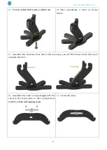
8)


Fix plate

 11

 and 

15

 by 

M2.5 x 10 screw

 and


M2.5 nut


9)


Fasten  the  screw  and  nut. 

Note:

Plate 

15

  with  white  rocker  arm  side  should  be 

Downward. 


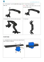
10)


Assemble the other foot at the same way. 


11)


Top view. 


Assemble the back feet 

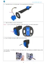
1)


Assemble the acrylic plate 

11

 to the 

13

.

 Note: 

The  direction  of  the 

11

  plate  can’t  be  put  on 

reverse side. The square hole of 

13

 plate in on the 

right side.


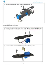
2)


Fasten the acrylic plate


11

 and


13


Содержание Bionic Robot Lizard

Страница 1: ...f you have interest in open source or making something cool welcome to join us Visit www sunfounder com for more About This Kit In this book we will show you how to build the bionic robot via description illustrations of physical components in both hardware and software respects You may visit our website www sunfounder com to download the related code and view the user manual on LEARN Get Tutorial...

Страница 2: ...ounder Compatible 6 Install Arduino IDE 6 Install the Driver 7 Add Libraries 7 Test 9 Assembly 14 Assemble the forefeet 14 Assemble the back feet 16 Lizard body 18 Assemble head and neck 21 Body head limb tail 25 Assemble expansion board 27 Adjusting 30 Case 1 The forefeet are inclined 30 Case 2 The back foot is inclined 32 Case 3 The Lizard can t stand steadily 33 ...

Страница 3: ...com 1 Components List Acrylic Plate You need to clean the acrylic plates before using Here takes one plate as example 1 Clean the residue by a tool with sharp point 2 Remove the stickers on the two faces of the plate ...

Страница 4: ... Components Qty M1 2 x 4mm Self tapping Screw 8 M2 x 10 Screw 6 M2 x 14 Screw 4 M2 5 x 8 Screw 14 M2 5 x 10 Screw 16 M3 x 6 Screw 4 M3 x 12 Screw 6 M2 Nut 8 M2 5 Nut 16 M3 Self locking Nut 6 M2 5 13 Copper Standoff 8 M3 x 25 Red Aluminum Standoff 1 ...

Страница 5: ...www sunfounder com 3 Electrical Components Name Components Qty 9g SF0180 Servo 3 Nano board 1 Expansion board 1 2S battery 1 Cable Spiral Wrap 1 Velcro Tape Length 35mm 1 Mini USB Cable 1 ...

Страница 6: ...www sunfounder com 4 IR Remote Control 1 IR Receiver Module 1 3Pin Anti reverse Cable 1 2S Lithium Battery USB Charger Cable 1 Phillips Screw Driver 1 Cross Socket Wrench 1 ...

Страница 7: ...ng you can control it walk by the remote controller You can also add other sensors on the Lizard like obstacles avoiding line following and so on There are remaining pins on the sensor shield You can find the schematic diagram of Sensor Shield at the file of Circuit Besides in order to control the robot in a more simple way there is a tutorial wrote for the visual programming How to use Lizard rob...

Страница 8: ...the sketches i e the code files to the board and then you can see experimental phenomena For more information you can refer to http www arduino cc Arduino Board SunFounder Compatible Arduino senses the environment by receiving inputs from many sensors and affects its surroundings by controlling lights motors and other actuators In this kit the SunFounder Nano board is used Install Arduino IDE The ...

Страница 9: ...g steps you can refer to the guide on Learning Getting Started with Arduino scroll down and see Install the Arduino Software After installing you will see Arduino icon on your desk and double click to open it Install the Driver If the driver is not installed the Nano board will not be recognized by your computer Therefore before using it please install appropriate driver For Windows users run PL23...

Страница 10: ...nfounder com 8 2 Input IRremote then the library will appear click Install button to install it 3 You can see the libraries just imported have appeared on the list by going to Sketch Include Library IRremote ...

Страница 11: ...T female pin into the red power of the Sensor Shield 3 Connect 3 servos and Infrared receive module with expansion board Insert 3 rocker arms into servos in that observe if they are rotate or not Note The Black wire of IR Receiver module connect to sensor shield pin 5 then yellow wire connect to GND pin Servo Sensor Shield IR Receiver Sensor Shield Orange 2 3 4 Black 5 Red Red Brown Yellow GND ...

Страница 12: ...display USB Device not recognized it means that you haven t installed the driver thus you need to install the driver below For Windows users run PL2303_Prolific_DriverInstaller_v1180B in the folder Driver For Mac users refer to the folder PL2303_MacOSX_1_6_1_20170620 in the folder Driver 5 Open the Arduino Software IDE Select File Open On the pop up window go to the Bionic Robot Kit for Arduino Li...

Страница 13: ...lect Arduino Nano The Processor is ATmega328 7 Go to Tools Port to select the port Your serial port may be different from what s shown here right click My Computer on desktop click Properties Device Manager Ports 8 Click the following button to upload ...

Страница 14: ... successfully Servo Test 10 Switch on the power you will find the 3 servos rotate from 0 degree to 180 degree and then stop at 90 degree If you haven t seen clear of the process you can press the Reset button on the Nano board the servo will rotate again Test IR Receiver 11 Click File Preference to enable display line numbers then select OK ...

Страница 15: ...e it display the value of button on the Serial Monitor Note Press the button on the remote controller gently If you press the button forcefully it will be default as long press and display FFFFFFF After testing extract the servo and the Infrared Module Note The axis of the servos is not moved accidentally in the subsequent installation If the axes are moved adjust them again before the installatio...

Страница 16: ...hown below In the following description the number will be used There is an independent picture of the following one you can refer to Acrylic Plate png Assemble the forefeet 1 Assemble the acrylic plate 11 to 12 Note The direction of the plate 11 can t be put on reverse side 2 Insert the plate 11 into the 12 ...

Страница 17: ...oks as the picture shown below after assembling 5 Assemble the other forefoot at the same way 6 Assemble the rocker arm packaged with the servo to the acrylic plate 15 then connect them by M1 2 x 4mm self tapping screw 7 Fasten the self tapping screw Do not over tighten it Or the screw may be broken ...

Страница 18: ...5 with white rocker arm side should be Downward 10 Assemble the other foot at the same way 11 Top view Assemble the back feet 1 Assemble the acrylic plate 11 to the 13 Note The direction of the 11 plate can t be put on reverse side The square hole of 13 plate in on the right side 2 Fasten the acrylic plate 11 and 13 ...

Страница 19: ...ing it looks as shown below 5 Assemble the other two back feet at the same way you will find the two back feet are in opposite direction 6 Assemble the rocker arm packaged with the servo to the acrylic plate 14 then connect them by M1 2 x 4mm self tapping screw 7 Fasten the screw ...

Страница 20: ...5x10 screw and M2 5 nut 9 Fasten the screw and nut Note Plate 14 with white rocker arm side should be Downward 10 Assemble the other foot at the same way 11 Top view Lizard body 1 Assemble the servo onto the acrylic plate 4 by the M2 x 10 screw and M2 nut ...

Страница 21: ...te 4 3 After assembling it looks as shown below Note 1 servo axis should be upward 2 Plain side of plate 7 should be downward 4 Insert the M2 x 14 screw and M2 nut as shown below Tips Put plate 4 7 and the servo at the right place then insert M2 nut and M2 x14 screw and fix by screwdriver ...

Страница 22: ... screw and M2 5 x 13mm Bi pass copper standoff into the plate 4 6 After assembling it looks as shown below Top view 7 Connect the following plate with servo screws Packaged with the servo the servo screws are within the smaller two of five screws ...

Страница 23: ...d M2 nut Assemble head and neck 1 Assemble the servo onto the acrylic plate 1 by the M2 x 10 screw and M2 nut Use M2 x 10 screw and M2 nut to combine the servo to 1 acrylic plate Note the servo line direction 2 Fasten the M2 5x8 screw and M2 5x13 copper standoff into the plate 1 ...

Страница 24: ...er com 22 3 Fasten the following plate with servo screw 4 After assembling it looks as shown below Note The feet should be forward Top view 5 Insert the acrylic plate 8 6 Fasten them with M2 5x10 screw and M2 5 nut ...

Страница 25: ...e the rocker arm packaged with the servo to the acrylic plate 5 then connect them by M1 2 x 4mm self tapping screw 8 Connect the acrylic plate 2 and 5 with M2 5 x 10mm screw and M2 5 nut 9 Fasten the following plate with servo screw ...

Страница 26: ...w sunfounder com 24 10 Insert the plate 8 into the plate 2 Note Be careful in case of breaking the acrylic plate 11 After assembling it looks as shown below 12 Fasten them with M2 5x10 screw and M2 5 nut ...

Страница 27: ...nfounder com 25 Body head limb tail 1 Insert the three acrylic plate together into the aluminum standoff in the order as shown below 2 Fix the aluminum standoff by M3 x 6mm screw 3 Insert the acrylic plate 9 ...

Страница 28: ...se M2 5 x 10mm screw and M2 5 nut to fix it 5 Connect the acrylic plate 10 6 and 14 with M3 x 12mm screw and M3 self locking nut 6 Tighten the other screw and nut Note Self locking screw do not need to be tightened too much as it need to swing ...

Страница 29: ...y M2 5 x 8mm screw 2 Insert the three servos into the Sensor Shield the numbers on the servos are as shown below Insert the 1 servo to the pin 2 2 servo to pin 3 3 servo to the pin 4 and IR receiver module to pin 5 Servo Sensor Shield IR Receiver Sensor Shield Orange 2 3 4 Black 5 Red Red Brown Yellow ...

Страница 30: ...www sunfounder com 28 3 Stick the Velcro to the plate 3 ...

Страница 31: ...www sunfounder com 29 4 Stick the batteries on the Velcro 5 Connect the battery case and the Sensor Shield together 6 In order to be clean you can tie all the wires together by cable pipe ...

Страница 32: ...ght one is behind Step 1 Open Lizard_robot ino file under the path Bionic Robot Kit for Arduino Lizard Code Lizard_robot Step 2 Find the statement int array_setup 90 90 90 Set the original angle of the servo The three 90 inside the array stands for the angle of the three servos the forefeet are controlled by number 1 servo When the left foot is in front and the right one is behind you should minus...

Страница 33: ...3 Upload the code to the Sensor Shield If it looks still inclined then continue to decrease until it looks vertical to its body 2 The left foot is behind but the right is in front You need to increase the value of the first servo ...

Страница 34: ...ed 1 The left foot is in front the right foot is behind The back leg is controlled by servo 3 when the left leg is in front but the right one is behind the third value in the array need be decreased 2 The left leg is in back but the right one is in front ...

Страница 35: ...Increase the value of the third 90 in the array Case 3 The Lizard can t stand steadily When the head is deviation counter clockwise and one of the forefoot can t stand steadily the second 90 in the array need to be decrease ...

Страница 36: ...ased When finishing adjusting you can control the Lizard by remote controller Now the Lizard is complete adjust you can use the remote controller to control the Liard moving From the figure below the 2 button to control Liard go forward 4 to turn left 6 to turn right 8 to ...

Страница 37: ...t limited to texts images and code in this manual are owned by the SunFounder Company You should only use it for personal study investigation enjoyment or other non commercial or nonprofit purposes under the related regulations and copyrights laws without infringing the legal rights of the author and relevant right holders For any individual or organization that uses these for commercial profit wi...

Отзывы: