background image

Bi-Spectrum Radiometric Detector   
User Manual 

Quick Configuration 


32 


            Issue  V1.0  (2019-10-08) 


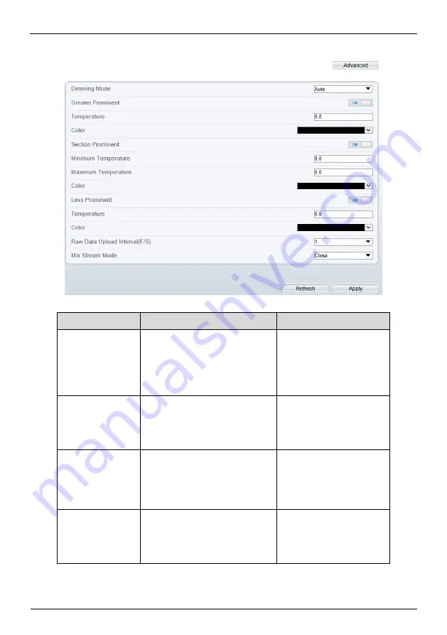
Figure 4-10


Advanced interface 


Table 4-4


Advance parameters 

Parameter 

Description 

Setting 

Dimming Mode 

There are auto and manual 
modes. It will show on 
temperature item. 

[Setting method] 

Select a value from the 
drop-down list box. 

[Default value] 

Auto 

Greater Prominent 

Enable that, the image will 
show the setting color if the 
temperature is higher than set 
value. 

[Setting method] 

Enter a value manually.   

Choose one color to 
show. 

Section Prominent 

Enable that, the image will 
show the setting color if the 
temperature is between 
minimum and maximum 
temperature. 

[Setting method] 

Enter a value manually.   

Choose one color to 
show. 

Less Prominent 

Enable that, the image will 
show the setting color if the 
temperature is lower than set 
value. 

[Setting method] 

Enter a value manually.   

Choose one color to 
show. 

Содержание SN-D2-F

Страница 1: ...Bi Spectrum Radiometric Detector User Manual Issue V 1 0 Date 2019 10 08 ...

Страница 2: ......

Страница 3: ...ngers which if not avoided may cause deaths or severe injuries It alerts you to moderate dangers which if not avoided may cause minor or moderate injuries It alerts you to risks Neglect of these risks may cause device damage data loss device performance deterioration or unpredictable results It provides a tip that may help you resolve problems or save time It provides additional information To pre...

Страница 4: ...h or too low temperature may cause image display anomaly of the camera and the camera will be damaged if it is working under such a condition for a long time If the camera is installed outdoors avoid direct sunlight at dawn and dusk on the camera lens and install a sunshield with frontal and rear positions adjusted according to the sunlight angle Avoid heavy loads intensive shakes and soaking to p...

Страница 5: ...ial Announcement All complete products sold by the manufacturer are delivered along with nameplates operation instructions and accessories after strict inspection The manufacturer shall not be held responsible for counterfeit products This manual may contain misprints technology information that is not accurate enough or product function and operation description that is slightly inconsistent with...

Страница 6: ...1 3 1 1 General Installation 11 3 1 2 Magnet Installation 13 3 2 Walling Installation 14 3 2 1 Bracket Installation 14 3 2 2 Magnet Installation 15 3 3 Packing list 17 4 Quick Configuration 19 4 1 Login and Logout 19 4 2 Main Page Layout 20 4 3 Change the Password 23 4 4 Browse Video 24 4 5 Install Plugins 26 4 5 1 Set Local Network Parameters 26 4 6 Thermal Settings 29 4 6 1 Temperature Parameter...

Страница 7: ... Setting 44 5 2 3 Scene 46 5 2 4 Set Psecudocolor 46 5 2 5 FFC Control 47 5 2 6 Noise Reduction 49 5 2 7 Enhance Image 50 6 Visible light Parameter Configuration 52 6 1 Access the Sensor Interface 52 6 2 Sensor Setting Parameter description 52 6 2 1 Mode 52 6 2 2 Image Adjust 53 6 2 3 Scene Mode 55 6 2 4 Exposure 56 6 2 5 WB Setting 57 6 2 6 Daynight 59 6 2 7 Noise Reduction 61 6 2 8 Enhance Image...

Страница 8: ...y camouflage and concealed object both in daytime or nighttime implementing round the clock monitoring Monitor the temperature field with object energy distributed The IR thermal imaging camera can show the temperature field of an object converting the invisible surface temperature distribution situation to a visible thermal image that reflects the surface temperature distribution situation of the...

Страница 9: ...n power self locking function 1 2 2 Product Features The shell of the machine adopts the material of high strength aluminum alloy die casting machine with anti corrosion materials anti corrosion treatment key parts filling nitrogen seal all weather protective design IP66 protection grade can adapt to the maritime and coastal defense environment such as salt fog video monitoring application Double ...

Страница 10: ...cable Table 1 1 Description of cores SN Port Description 1 Power DC 12 V 2 USB Connect USB port 3 Video port Connect to video screen 4 G Ground earth wire 5 Network port Connect to a standard Ethernet cable 6 Orange RS232 RX Blue RS232 TX Purple ALARM OUT Brown ALARM OUT COM Grey ALARM IN Pink ALARM IN COM Yellow RS232 COM ...

Страница 11: ...Bi Spectrum Radiometric Detector User Manual Device Dimensions Issue V1 0 2019 10 08 9 2 Device Dimensions Figure 2 1 shows the dimensions of the Bi Spectrum Radiometric Detector ...

Страница 12: ...ser Manual Device Dimensions 10 Issue V1 0 2019 10 08 Figure 2 1 Dimensions unit mm 92 65 42 43 8 0 5 42 9 25 58 80 5 4 M3 Depth 6 2 1 4 20UNC 1A Depth 8 4 M3 Depth 6 116 4 50 101 107 123 10 4 126 φ 6 3 φ55 3 φ4 5 S ym metrically array ...

Страница 13: ... cabinet door s mounting surface drill three holes based on the marks on the sticker as shown in Figure 3 1 It is recommended that the drill size be φ3 φ4 mm and it is better to remove the label after the hole is finished to avoid affecting heat dissipation Figure 3 1 Stick the sticker Step 2 Take out the camera and attach the camera to the corresponding step 1 on the back of the cabinet door as s...

Страница 14: ...re 3 2 Put the device Step 3 Take out the PWM3 6 screws in the accessory and fix them on the screw holes of the camera through the hole punched in step 1 on the front of the door and tighten the screws Figure 3 3 Install the device Step 4 Connect the multi connector cable start up the device End ...

Страница 15: ...the camera and the magnet bracket install the magnet bracket on the back of the camera and fix it with the PWM3 6 screws as shown in Figure 3 4 Figure 3 4 Install the magnet bracket Step 2 Attach the camera assembly to the back of the cabinet door as shown in Figure 3 5 Connect the multi head combination cable to start up the camera Figure 3 5 Fixed the magnet bracket Step 3 Combine with the image...

Страница 16: ...e drill three holes based on the marks on the sticker drive three swell plastic buttons into the holes Step 2 Take out the gimbal bracket align the three through holes at the bottom of the bracket with the expansion rubber and fix the bracket with the self tapping screws in the accessory as shown in Figure 3 6 Figure 3 6 Install the gimbal bracket Step 3 Take out the camera align the 1 4 UNC hole ...

Страница 17: ... bottom bracket nut and tighten the locking screw on the bracket to complete the angle adjustment End 3 2 2 Magnet Installation Step 1 Open the label 2 in the positioning label and attach it to the mounting position on the wall Drill the hole in the small round hole of the positioning label with the drill bit and insert the expansion rubber into the hole Step 2 Take out the camera and the magnet b...

Страница 18: ...stall the magnet bracket and camera Step 3 Attach the camera assembly to the sticker position and remove the self tapping screws to secure the camera assembly as shown in Figure 3 9 Figure 3 9 Install the magnet bracket and camera Step 4 Connect the multi head combination cable to start up the camera End ...

Страница 19: ...t to check if there is any omission please contact the seller Table 3 1 Packing list No Item Quantity Picture 1 Camera 1 2 Power supply and cable 1 3 User manual 1 4 Installation location sticker 1 5 Screws PWM 3 6 4 6 Focus lever 1 7 Magnet bracket 1 8 Self tapping screw PT4 40 4 9 Swell plastic button 4 10 Network access port protective cover and waterproof rubber seal 1 ...

Страница 20: ...Bi Spectrum Radiometric Detector User Manual Device Installation 18 Issue V1 0 2019 10 08 11 Gimbal bracket 1 ...

Страница 21: ... the Internet Explorer enter the IP address of IP camera default value 192 168 0 120 in the address box and press Enter The login page is displayed as shown in Figure 4 1 Figure 4 1 Login page Step 2 Input the User name and password The default user name is admin The default password is admin Change the password when you login the system for first time to ensure system security You can change the ...

Страница 22: ... display after you log out of the system 4 2 Main Page Layout On the main page you can view real time video set parameter Video parameter Video control and log out of the system Figure 4 2 is shown the main page layout Table 4 1 lists the elements on the main page layout Switch channel to show light video or thermal video channel 1 is light live video channel 2 is thermal live video ...

Страница 23: ...Bi Spectrum Radiometric Detector User Manual Quick Configuration Issue V1 0 2019 10 08 21 Figure 4 2 Main page layout light 6 7 8 9 10 11 12 13 14 15 1 2 3 4 5 Figure 4 3 Thermal live video ...

Страница 24: ...nnel 1 is light live video Channel 2 is thermal live video 7 Stream Three are four streams in channel 1 there are two streams in channel 2 Choose one type from drop down list 8 Pause Start Close live video or play live video 9 Live Smooth Switch image quality 10 Audio Open or close audio 11 Interphone Open or close interphone 12 Sensor setting Click the icon it will access to sensor setting 13 Sna...

Страница 25: ...st temperature of the full screen the lowest temperature of the area the highest temperature of the area End 4 3 Change the Password Description You can click to change the password for logging in to the system Procedure Step 1 Click in the upper right corner of the main page The Change Password dialog box is displayed as shown in Figure 4 4 ...

Страница 26: ...ayed the password is successfully changed If the password fails to be changed the cause is displayed For example the new password length couldn t be less than eight Step 4 Click OK The login page is displayed End 4 4 Browse Video User can browse the real time video in the web management system Preparation To ensure the real time video can be play properly you must perform the following operation w...

Страница 27: ...Options Security Customer level and set Download unsigned ActiveX control and initialize and script ActiveX controls not marked as safe for scripting under ActiveX controls and plug ins to Enable as shown in Figure 4 6 Figure 4 6 Configuring ActiveX control and plug ins Step 3 Download and install the player control as prompted The login page is display when the control is loaded ...

Страница 28: ...in page Procedure Step 1 Click the message download and install the plugin follow the prompts Step 2 Reopen the browser after installation End 4 5 1 Set Local Network Parameters Description Local network parameters include IP protocol IP address Subnet mask Default gateway Dynamic Host Configuration Protocol DHCP Preferred Domain Name System DNS server Alternate DNS server MTU Procedure Step 1 Cho...

Страница 29: ...of 32 bits Setting method Select a value from the drop down list box Default value IPv4 DHCP The device automatically obtains the IP address from the DHCP server Setting method Click the option button NOTE To query the current IP address of the device you must query it on the platform based on the device name DHCP IP IP address that the DHCP server assigned to the device N A IP Address Device IP a...

Страница 30: ...hod Enter a value manually Default value 192 168 0 2 MTU Set the maximum value of network transmission data packets Setting method Enter a value manually NOTE The MTU value is range from 800 to 1500 the default value is 1500 Please do not change it arbitrarily Step 3 Click OK If the message Apply success is displayed click OK The system saves the settings The message Set network pram s success Ple...

Страница 31: ...mperature display mode Operation Procedure Step 1 Choose Configuration Thermal Temperature Parameters The Temperature Parameters page is displayed as shown in Figure 4 9 Figure 4 9 Temperature Parameters interface Step 2 Set the parameters according to Table 4 3 Table 4 3 Temperature parameters Parameter Description Setting Temperature Unit Celsius and Fahrenheit temperature units are available Se...

Страница 32: ...nt should be 7 2 The measured object temperature is 37 and actual temperature is 30 so the correction coefficient should be 7 Setting method Enter a value manually Default value 0 00 Area Temperature Display Mode The display position of temperature information on the live video image Setting method Select a value from the drop down list box Default value Low left Font Border Enable to bold the fon...

Страница 33: ...the drop down list box Default value General Display Alarm Area N A Setting method Enable or disable Default value Disable Area Alarm Interval N A Setting method Enter a value manually ranges from 1 to 1800 Default value 10 Temperature range It depends the device different devices have different modes there are two ranges such as 20 150 40 150 Setting method Select a value from the drop down list ...

Страница 34: ...reater Prominent Enable that the image will show the setting color if the temperature is higher than set value Setting method Enter a value manually Choose one color to show Section Prominent Enable that the image will show the setting color if the temperature is between minimum and maximum temperature Setting method Enter a value manually Choose one color to show Less Prominent Enable that the im...

Страница 35: ...rop down list box Default value 1 Mix Stream Mode This function is used for thermal and visible lighting image to mix There are close mode 1 and mode 2 Default value Close Step 3 Click Apply The message Apply success is displayed the system saves the settings End 4 6 2 Temperature Area Operation Procedure Step 1 Choose Configuration Thermal Temperature Area The Temperature Area page is displayed a...

Страница 36: ...ion Setting Channel N A Setting method Select a value from the drop down list box Default value 1 Measure Mode Set at temperature parameter interface N A Enable Tick to enable the areas N A ID It ranges from 0 to 19 N A Name Area name of temperature area Setting method Enter a value manually Type Type of temperature area ID 0 is default rectangle area which is full screen Setting method Select a v...

Страница 37: ...arm when the surveillance object temperature reaches the alarm value Setting method Enter a value manually Default value 50 00 Maximum Alarm Value At section alarm type the device would not alarm when the temperature is higher than maximum alarm value Setting method Enter a value manually Default value 60 00 Emission Rate The emission rate is the capability of an object to emit or absorb energy Th...

Страница 38: ...ea selected Figure 4 12 Temperature Area Setting Interface 4 Click Apply the message Apply success is displayed the temperature area is set successfully Delete a temperature area 1 Select an area ID 2 Click the temperature area and right click 3 Remove the tick of area ID 4 Click Apply the message Apply success is displayed the temperature area is deleted successfully Step 4 Click Apply The messag...

Страница 39: ... Show Shield Area then the setting shield will show on live video Step 4 Click left mouse button to set area click right mouse button to end the setting Step 5 Click Clear to clear the shield area End 4 6 4 Schedule Linkage Operation Procedure Step 1 Choose Configuration Thermal Schedule Linkage The Schedule Linkage page is displayed as shown in Figure 4 14 ...

Страница 40: ...se button drag and release mouse to select the alarm time within 0 00 24 00 from Sunday to Saturday NOTE When you select time by dragging the cursor the cursor cannot be moved out of the time area Otherwise no time can be selected Method 3 Click in the alarm time page to select the whole day or whole week Deleting alarm time Click again or inverse selection to delete the selected alarm time Step 5...

Страница 41: ... Near focus far focus Setting method Click the button Lock focus position N A Setting method Tick Mapping point You need map three points at two channels Points are correspond of each The three points should cover most areas and two points are located in the diagonal display of the picture Point one is green cross Point two is red cross Point three is blue cross Setting method Select from drop lis...

Страница 42: ...ment or scenario change is bad point You can delete the bad point by bad point check function Procedure Step 1 Choose Configuration Thermal Bad Point Check The Bad Point Check page is displayed as shown in Figure 4 16 Figure 4 16 Bad Point Check Bad Point 1 Bad Point 2 Step 2 Click the white point at image click Apply to recover the bad point as shown in Figure 4 17 ...

Страница 43: ...d point Step 3 Click Reset to return the previous settings Step 4 Click Apply The message Apply success is displayed the system saves the settings End 4 6 7 LED Control Parameter Procedure Step 1 Choose Configuration Thermal LED Control Parameter The LED Control Parameter page is displayed as shown in Figure 4 16 ...

Страница 44: ...s Close Open Flicker Timing Setting method Select from drop list Flicker interval 100 10000 ms Display mode is Flicker and user need to set an interval to flash the LED Setting method Input an integer from 100 to 10000 Schedule Display mode is Timing user to set time to open LED Setting method Drag mouse to select the time or click to choose one day or one week Step 2 Click Apply to save the setti...

Страница 45: ...interface Table 5 1 Sensor Setting interface Parameter Description Full Screen It enlarges and displays the image in full screen Hide Info It refers to the function that hides the IP address code rate and other information of the functioning imaging device on the Client Side Note This function is only applicable to the Client Side and not for the WEB Side Sensor Configure It is used for configurin...

Страница 46: ...escription 5 2 1 Mode Operation procedure Step 1 Click Mode tag on sensor setting interface the time segment page is displayed as shown in Figure 5 2 Figure 5 2 Time Segment page Step 2 Choose Debug Model in the lower left corner to activate the sensor setting page Step 3 Set the switch mode parameters Step 4 Click save to save the setting End 5 2 2 Image Setting Figure 5 3 shows the image setting...

Страница 47: ... brightness of an image As the value increases the image becomes brighter Setting method Drag the slider Default value 50 Contrast It indicates the contrast between the bright part and the dark part of an image As the value increases the contrast increases Setting method Drag the slider Default value 50 Sharpness It indicates the sharpness of the image plane and the sharpness of the image edge The...

Страница 48: ... scene interface Figure 5 4 Scene interface Provide the selection of image pixel locations Normal the image is not flipped Horizontal the image is flipped left and right Vertical the image is flipped up and down Horizontal Vertical the image upside down and reversal 5 2 4 Set Psecudocolor Figure 5 5 shows the set pseudocolor interface ...

Страница 49: ... temperature field of the scene is converted to images by using the grayscale ranging from 0 to 255 Different polarity modes can be converted to different display images The most common setting is white hot a hotter object is displayed brighter than a colder object or black hot a hotter object is displayed darker than a colder object The difference between two modes lies in that the temperatures c...

Страница 50: ...field By means of FFC the camera can update the correction coefficients to output more uniform images Throughout the FFC process the video image is frozen for two seconds and a static frame image is displayed After the FFC is complete the image is automatically recovered Repeated FFC operations can prevent the grainy and image degradation problems The FFC is especially important when the temperatu...

Страница 51: ...r the specified period Choose manual mode when you feel that the image is obviously degraded but the automatic FFC is not performed you can use the manual FFC function to check whether the image quality can be improved FFC Interval min In the automatic FFC mode the FFC interval ranges from 10 to 255 minutes How to set Drag the slider Default value 5 Temper Interval In the automatic FFC mode the FF...

Страница 52: ...Parameter Description Setting 2 DNR Decrease the image noise How to set Select from the drop down list box Drag the slider to adjust max strength Default value Auto 3 DNR Decrease the image noise How to set Select from the drop down list box Drag the slider to adjust max strength Default value Auto End 5 2 7 Enhance Image Figure 5 8 shows the screen adjustment interface and Table 5 5 shows the scr...

Страница 53: ...al Parameter Configuration Issue V1 0 2019 10 08 51 Figure 5 8 Enhance image interface Table 5 5 Screen adjustment parameter description Parameter Meaning Configuration Method Defog Decrease the image fog How to set Drag the slider Default value 50 End ...

Страница 54: ... interface move the cursor to the real time video page and right click on the page A shortcut menu is displayed as shown in Figure 6 1 Figure 6 1 Sensor Setting interface Step 2 Choose Sensor Configure and the Sensor Setting dialog box appears End 6 2 Sensor Setting Parameter description 6 2 1 Mode Operation procedure Step 1 Click Mode tag on sensor setting interface the time segment page is displ...

Страница 55: ...tion Issue V1 0 2019 10 08 53 Figure 6 2 Mode page Step 2 Choose Debug Model in the lower left corner to activate the sensor setting page Step 3 Set the time segment parameters Step 4 Click save to save the setting End 6 2 2 Image Adjust Figure 6 3 shows the Image Adjust tab page ...

Страница 56: ...lue increases the contrast increases Setting method Drag the slider Default value 50 Brightness It indicates the total brightness of an image As the value increases the image becomes brighter Setting method Drag the slider Default value 50 Sharpness It indicates the border sharpness of an image As the value increases the borders become clearer and the number of noise points increases Setting metho...

Страница 57: ...ace Figure 6 4 Scene mode interface Table 6 2 describes the FFC mode parameters Table 6 2 FFC mode parameters description Parameter Description Configuration Method Scene It indicates the working mode of a camera Outdoor It applies to outdoor scenarios Indoor It applies to indoor scenarios Configuration method Select from the drop down list Default value Outdoor ...

Страница 58: ...right Vertical The image flips up and down Horizontal and vertical The image rotates at 180 degrees Setting method Select a value from the drop down list Default value Normal Freeze It can be set to on or off It is used to enable or disable the image freezing function of a camera Setting method Tick the Freeze status Default value Disable 6 2 4 Exposure Figure 6 5 shows the Exposure interface Figu...

Страница 59: ...alue Auto Max Shutter The device automatically adjusts the shutter time based on the ambient brightness The shutter time is less than or equal to the value of this parameter Setting method Select a value from the drop down list Default value 1 25 Max Gain The device automatically adjusts the gain based on the external light The gain is less than or equal to the value of this parameter Setting meth...

Страница 60: ...tion Method Mode It is adjusted based on application scenarios to improve the fidelity of the image color The WB modes include Auto In automatic white balance WB mode the system automatically performs white balance based on the monitoring environment Tungsten Fluorescent Daylight Shadow Manual In manual WB mode you can manually select a WB mode based on the monitoring environment Setting method Se...

Страница 61: ...stomized Setting method Drag the slider Default value 0 Blue Gain It indicates the gain applied to blue channels As the value increases the color temperature becomes higher This parameter is valid when Manual Mode is set to Customized Setting method Drag the slider Default value 0 6 2 6 Daynight The day night mode settings vary based on device models For details see the following sections Figure 6...

Страница 62: ...e The image is colored and the filter is in the day state preventing infrared light from entering the sensor Night mode The image is black and white and the filter is in the night state allowing infrared light to enter the sensor Timing Set day to night time and night to day time to switch the daynight mode Setting method Select a value from the drop down list Default value Auto TRANSI D N dB It d...

Страница 63: ...uto mode The value of TRANSI D N must be greater than the value of TRANSI N D Setting method Drag the slider Default value 30 Delay s The delay time of day to night or night to day This parameter is valid in auto mode Setting method Drag the slider Default value 0 DTN Time Time of day to night Setting method Select a value from the drop down list Default value 18 00 NTD Time Time of night to day S...

Страница 64: ...ct from the drop down list Default value Auto Max Strength It is valid in auto noise filter mode When the parameter value is 0 the noise filter is disabled When the parameter value is greater than 0 the noise filter is enabled and the system automatically adjusts the noise filter level based on the ambient brightness without exceeding the value of this parameter Setting method Drag the slider Defa...

Страница 65: ...e noise filter is disabled When the parameter value is greater than 0 the noise filter is enabled and the system automatically adjusts the noise filter level based on the ambient brightness without exceeding the value of this parameter Setting method Drag the slider Default value 50 6 2 8 Enhance Image Figure 6 9 shows the enhance image interface and Table 6 7 shows the enhance image parameter Fig...

Страница 66: ...n image in the highlight environment When HLC is enabled the total brightness of an image is reduced allowing you to view objects in front of the highlight Setting method Tick the HLC mode and drag the slider Default value 50 BLC It provides a clearer view of an image in the backlight environment When BLC is enabled the total brightness of an image increases allowing you to view objects in front o...

Страница 67: ... emission rate is the ratio of the energy emitted by an object at a specific temperature to that emitted by an ideal radiator at the same temperature The range of emission rate value is 0 0 to 1 0 generally Materials Temperature Emissivity Gold High purity 227 440 0 02 Aluminum foil 27 81 0 04 Aluminum sheet 27 81 0 18 Aluminum used for families flat 23 73 0 01 Aluminum plate 98 3 purity 227 440 0...

Страница 68: ...h polish 247 476 0 03 Brass Tough rolled polished metal wire 21 70 0 04 Tinned Iron Light 0 13 Iron plate Rust eaten 20 68 0 69 Rolled steel sheet 21 71 0 66 Ferric oxide 100 212 0 74 Wrought iron 21 70 0 94 Fused iron 1299 1399 3270 2550 0 29 Copper Polished 21 117 70 242 0 02 Copper Polished not reflected 22 72 0 07 Copper Heavy oxide Board 25 77 0 78 Enamel Fuse on iron 19 66 0 9 Formica Plate ...

Страница 69: ... 8 Carbon T carbon 0 9 ash 127 260 0 81 Concrete 0 94 Glass Glossy 22 72 0 94 Granite Surfaced 21 70 0 85 Ice 0 32 0 97 Marble I Polished grey 22 72 0 93 Asbestos board 23 74 0 96 Asbestos paper 38 100 0 93 371 700 0 95 Asphalt Paving the road 4 39 0 97 Paper Black tar 0 93 Paper White 0 95 Plastic White 0 91 101 300 0553 01 ...

Отзывы: