background image

Содержание RCU-9310B

Страница 1: ...TM 8129000504 REMOTE CONTROL UNIT for RT 90008 HF SSB TRANSCEIVER RCU 93108 OPERATION AND MAINTENANCE MANUAL fj SUNAIR 3005 Southwest Third Avenue Fort Lauderdale Florida 33315 3312 ...

Страница 2: ...fied or repaired without authorization subject to misuse abuse accident water damage or other neglect or has its serial number defaced or removed THIS WARRANTY IS ESPECIALLY IN LIEU OF ANY AND ALL OTHER WARRANTIES EXPRESSED OR IMPLIED INCLUDING ANY IMPLIED WARRANTY OF MERCHANT ABILITY OR FITNESS FOR A PARTICULAR PURPOSE The obligation and responsibility of Sunair shall be limited to that expressly...

Страница 3: ...e Oo 0 e IQJ 0 f i jjEl 000 ij J 000 rrm JEJ I I II U 11 l I I 0 o OFFo 0 D D RCU 9310 REMOTE CONTROL UNIT 0 I RCU 8310 l e e OPERATION AND MAINTENANCE MANUAL FOURTHEDITIONFEBRUARY28 1997 Page change 1 03 24 99 Page change 2 08 26 99 ...

Страница 4: ...ice Dept Sunair Electronics Inc 3101 SW Third Avenue Ft Lauderdale FL 33315 3389 U S A Telephone Fax E Mail 954 525 1505 954 765 1322 techsupport sunairhf com TRAINING Sunair offers training programs of varying lengths covering operation service and maintenance of all Sunair manufactured equipment For details please contact the Product Support Department ...

Страница 5: ...ALLATION AND MOUNTING INFORMATION 2 4 1 GENERAL INSTALLATION 2 4 2 BASE STATION INSTALLATION 2 4 3 RACK INSTALLATIONS Ill OPERATION 3 1 GENERAL 3 2 PRIMARY OPERATIONS ISUNAIR RCU 9310 I Page 1 1 1 1 1 1 1 2 1 2 1 3 1 3 2 1 2 1 2 1 2 2 2 2 2 9 2 9 3 1 3 3 3 2 1 REMOTE TRANSCEIVER SET UP FOR MODE AGC AND TRANSMIT POWER 3 3 3 2 2 ESTABLISHING AN OPERATING FREQUENCY 3 5 3 2 3 TRANSMIT TUNING 3 6 3 2 4...

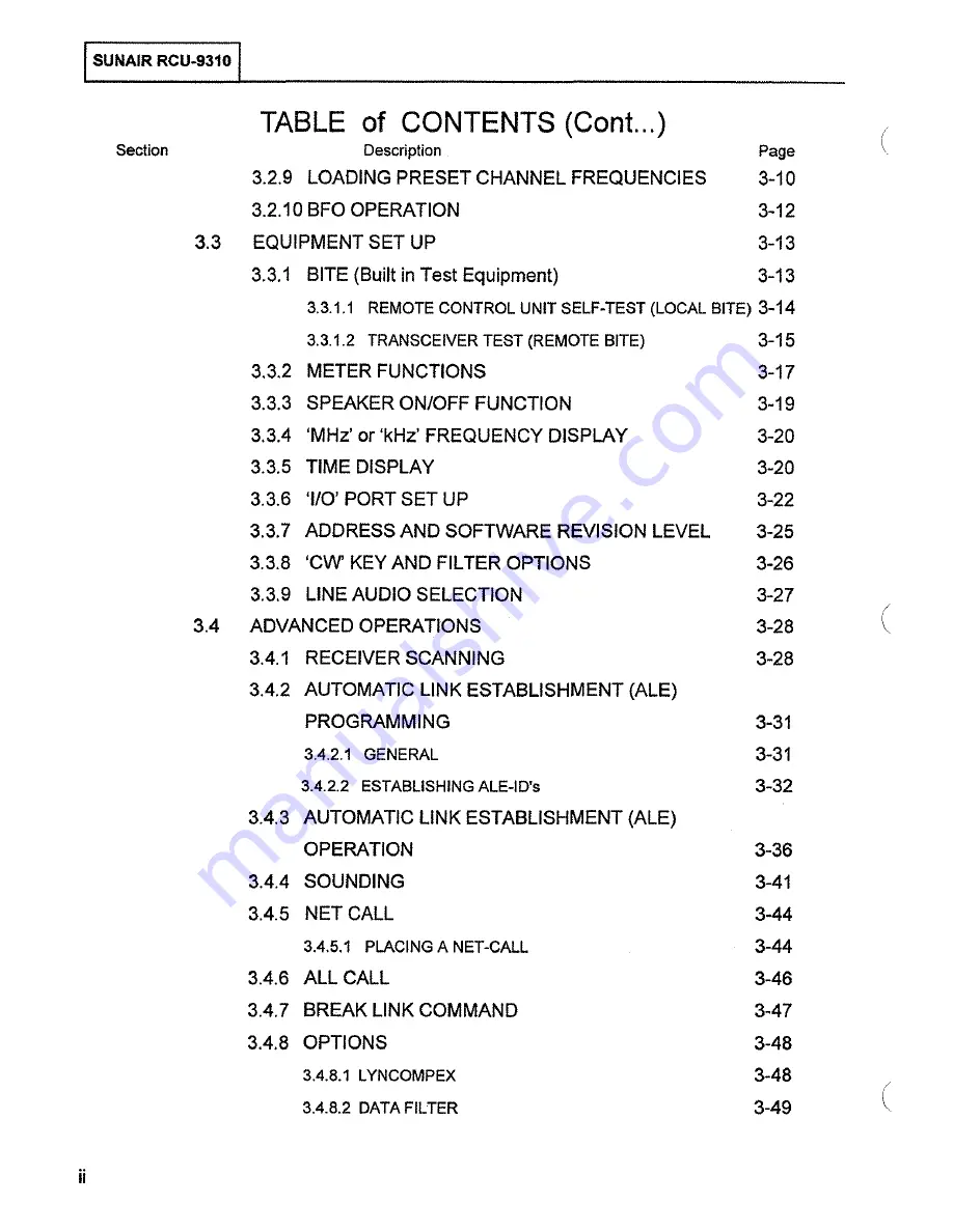
Страница 6: ...SPLAY 3 20 3 3 5 TIME DISPLAY 3 20 3 3 6 I O PORT SET UP 3 22 3 3 7 ADDRESS AND SOFTWARE REVISION LEVEL 3 25 3 3 8 CW KEY AND FILTER OPTIONS 3 26 3 3 9 LINE AUDIO SELECTION 3 27 3 4 ADVANCED OPERATIONS 3 28 3 4 1 RECEIVER SCANNING 3 28 3 4 2 AUTOMATIC LINK ESTABLISHMENT ALE PROGRAMMING 3 31 3 4 2 1 GENERAL 3 31 3 4 2 2 ESTABLISHING ALE ID s 3 32 3 4 3 AUTOMATIC LINK ESTABLISHMENT ALE OPERATION 3 3...

Страница 7: ...ONLY MEMORY EPROM U13 and U14 4 3 4 2 2 4 ELECTRICALLY ERASABLE PROGRAMMABLE READ ONLY MEMORY EEPROM US 4 4 4 2 2 5 STATIC RANDOM ACCESS MEMORY SRAM U3 4 4 4 2 2 6 OPTIONAL SMART WATCH U14 A 4 4 4 2 3 OPTOCOUPLER ASSEMBLY 3A2A1A1 4 4 4 2 4 AUDIO REMOTE AUDIO ASSEMBLIES 3A2A2 3A2A4 4 4 4 2 5 1 0 ASSEMBLY 3A2A3 4 5 4 2 6 POWER SUPPLY ASSEMBLIES 3A3 3A3A1 and 3A3A2 4 6 v FAULT ISOLATION MAINTENANCE A...

Страница 8: ...LY FAULT 5 6 5 5 TROUBLESHOOTING WITH SELF SURVEILLANCE BITE 5 6 5 5 1 AC POWER SUPPLY 5 6 5 5 2 INSTALLATION OF NEW BACKLIGHTING DEVICES FOR FRONT PANEL LCD S 5 12 5 6 TEST EQUIPMENT REQUIRED OR EQUIVALENT 5 16 5 7 TEST AND ALIGNMENT 5 16 5 7 1 TRANSMIT REMOTE AUDIO 5 16 5 7 2 RECEIVE REMOTE AUDIO 5 20 5 7 3 SOFTWARE SWITCH SETTING CHECKS 5 23 5 8 SCHEMATICS AND PARTS LISTS 5 25 iv ...

Страница 9: ...endent Sideband LCD Liquid Crystal Display LCL Local LED Light Emitting Diode LK Link LO Local Oscillator LP LPX Lincompex LRU Lowest Repairable Unit LSB Lower Sideband LT Light LVL Level MAN Manual M CH Manual Channel MED Medium MHz Megahertz MIC Microphone MIL STD Milijary Standard MNL Manual ms Millisecond MTTR Mean Time To Repair MTR Meter NAR Narrow 0 0 Olive Drab PA Power Amplifier PC Printe...

Страница 10: ... Display Information Location 3 2 Figure 3 2 1 RCU 9310 Remote Control Display Screens 3 4 Figure 3 2 2 RCU 9310 Operating Controls 3 5 Figure 3 2 5 RCU 9310 Operating Controls 3 7 Figure 3 2 7 RCU 9310 Operating Controls 3 8 Figure 3 2 8 RCU 931 0 Operational Controls 3 9 Figure 3 2 9 1 RCU 9310 Channel Loading Controls 3 10 Figure 3 2 9 2 RCU 931 0 Feature Display 3 11 Figure 3 2 10 RCU 9310 Dis...

Страница 11: ... 3 27 Figure 3 3 9 1 RCU 9310 Feature Menu Select Display 3 28 Figure 3 3 9 2 Line Audio Selection Menu Display 3 28 Figure 3 4 1 1 Operational Display for Channelized Mode 3 29 Figure 3 4 1 2 Feature Menu Display for SCAN Select Key 3 29 Figure 3 4 1 3 Feature Menu Display for SCAN Function 3 30 Figure 3 4 1 4 Feature Menu Display for SCAN LOAD Select Key 3 30 Figure 3 4 2 2 1 RCU 9310 Feature Me...

Страница 12: ...ntrol Feature Menu Display 3 49 Figure 3 4 8 5 1 Feature Menu Display for Pre selector Selection 3 50 THEORY OF OPERATION Figure 4 1 RCU 9310 Remote Control Unit Block Diagram FAULT ISOLATION MAINTENANCE AND REPAIR 4 2 Figure 5 2 1 1 Top Bottom and Card Cage Covers Removal 5 2 Figure 5 4 1 1 RCU 9310 Feature Menu BITE Selection 5 3 Figure 5 4 1 2 RCU 931 0 BITE Submenu 5 3 Figure 5 4 1 3 Top View ...

Страница 13: ...2 PC Assembly Front Panel 3A1A1 page 1 of 6 5 28 Figure 5 8 3 PC Assembly Mother Board 3A2A5 page 1 of 4 5 34 Figure 5 8 4 PC Assembly CPU 3A2A1 page 1 of 8 5 38 Figure 5 8 5 PC Assembly OPTOCOUPLER 3A2A1A1 page 1 of 3 5 46 Figure 5 8 6 PC Assembly Audio 3A2A2 page 1 of 9 5 49 Figure 5 8 7 PC Assembly Audio Remote 3A2A4 page 1 of 2 5 58 Figure 5 8 8 PC Assembly 1 0 Board 3A2A3 page 1 of 4 5 60 Fig...

Страница 14: ... ITHIS PAGE INTENTIONALLY LEFr BLANK I ...

Страница 15: ...nel In addition the RCU 931 o allows the remote operator to access and use the transceiver s advanced automated functions receiver scanning of preprogrammed channels programming and execution of Automatic Link Establishment ALE operations sounding broadcasting to selected stations in a predefined network and network call broadcasting to all stations in a network 1 3 GENERAL DESCRIPTION The RCU 931...

Страница 16: ...and receive audio 0 dBm adjustable into 600 ohms BITE Fault isolated to module level LRU descriptive readouton front panel and individual module indication INPUT POWER 26 VDC 15 120 240VAC 15 AC DCAuto Changeover AUDIO OUTPUT 5 Watts into internal speaker 5 THO Two selectable lines at 20 dBm to 1 0 dBm into 600 ohms Headset low impedance SQUELCH Syllabic AUDIO INPUT Microphone aux connector and tw...

Страница 17: ... 8076002192 The following is a list of optional equipment or accessories available for use with the RCU 931 0 Remote Control Unit OPTIONAL EQUIPMENT ACCESSORIES SUNAIR MODEL PART NUMBERS Headset 0840200005 Headset Lightweight 1010690027 CW Key with Phone Plug 5024000994 Handset Assembly 8076000793 Desktop Microphone 8076000891 Shroud Kit for Rackmounting 1004770014 O D 1004770022 GRAY Power Cord A...

Страница 18: ...ISUNAIR RCU 9310 I lrHIS PAGE INTENTIONALLY LEFT BLANK 1 4 I ...

Страница 19: ...tion of the shipment A full report ofthe damage should also be forwarded to Sunair s Product Services Department Please be sure to include the following information for prompt service a ORDER NUMBER b MODEL AND SERIAL NUMBER c NAME OF TRANSPORTATION AGENCY d APPLICABLE DATES Upon receipt of this information Sunair will make arrangements for repair or replacement 2 3 RETURN OF EQUIPMENT TO FACTORY ...

Страница 20: ...will depend upon the care and thoroughness taken during installation 12 4 1 GENERAL INSTALLATION I 2 2 For installation and operation with KW equipment modems and other peripherals use this manual in conjunction with their respective operating manuals for complete installation information Before starting installation carefully plan equipment locations to ensure that the operating environment is su...

Страница 21: ...el CW Key to J1 on front panel Control Lines from J6 on rear panel to remote connector J8 on rear panel of RT 9000 Audio lines from J4 on rear panel to Audio connector J5 on rear panel of RT 9000 Connect modem audio and keyline to J3 on rear panel of RCU 9310 NOTE See Figure 2 4 1 1 See Figure 2 4 1 1 See Figure 2 4 1 1 See Figure 2 4 1 1 See Figure 2 4 1 1 See Figures 2 4 1 1 2 4 1 2 2 4 1 3 and ...

Страница 22: ... PTT J3 Auxllliary Input J4 Headphones J2 r 111 l I I I I I Ol DODO FRONT PANEL CWKeyJ1 J5 For use with optional DC power converter 1h OC 6 REAR PANEL r 1 I I TOP VIEW Figure 2 4 1 1 RCU 9310 Outline Dimensions and Connector Locations ...

Страница 23: ...tem i e RS 232 FSK Tones RS 422 or RS 485 If multiple RT 9000 A are being controlled in the system a mechanical switch or electrical switch must be installed at the RCU 931 0 Remote audio in order to select Transmit and Receive audio to from only one RT 9000 A at a time Figure 2 4 1 2 Interconnection of RCU 931 0 Remote Control Unitand RT 9000 Receiver Page change 2 8 26 99 2 5 ...

Страница 24: ...T MAX F S K_T O N E 2 _________________ F S K_T O N E TONE MODEM CONTROL INTERCONNECT XMT HIGH AS 422 RCV HIGH 8 XMT LOW RS 422 RCV LOW 9 RCV HIGH AS 422 XMT HIGH 6 ACV LOW RS 422 XMT LOW 7 RS 422 CONTROL INTERCONNECT 4000 FT MAX 1 8 9 MULTIPLE 6 7 B 9 6 7 R S 4 8 5 H l GH 8 8 AS 485 LOW 9 9 AS 485 CONTROL INTERCONNECT 4000 FT MAX H 8 f 9 Hi 8 9 RT 9000 AI MULTIPLE RT 9000 IAJ Figure 2 4 1 3 FSK R...

Страница 25: ...lOP REMOTE AUO O A c E F G H J T_ Rc _ANSMJ T AUD _ l_ O_ _ TRANSMl T _ _ AcoU _D clDc _ c__ __ ISUNAIR RCU 9310 I RT 9000 A 19 PIN CONNECTOR P NJQ1 1 l40004 PW06A 14 l9P AUDIO JS Figure 2 4 1 4 RCU 9310 Remote Audio to RT 9000 A Audio Wiring Diagram 2 7 ...

Страница 26: ...ONNECTQF i AUDIO _ 19 PlN CONNECTOR PN_ 1011140004 PI OSF 14 SP CABLE 9 CONDUCTOR U24 PN 011200015 BUSHING TELESCOPING PN 0700550046 a m VIHT V IO 1 HT BLU IHT GRN v HT YE IHT ORN WHT REO WHT SAF I IHT BLK GR 0 1 HT GAY BAN acu GRN m ORN RGO ee en c Si II 0 c 0 ...

Страница 27: ...nal lines and AC and DC power 12 4 3 RACK INSTALLATIONS I The remote control unit may be mounted in a standard nineteen inch 19 rack using the Shroud Kit Sunair p n 1004770014 00 or 1004770022 Gray The kit includes rack mounting brackets filler panels and trim strips and associated hardware In the rack mounted configuration the remote control unit requires a standard panel space of seven inches 7 ...

Страница 28: ...ISUNAIR RCU 9310 I ITHIS PAGE INTENTIONALLy LEFT BLANK 2 10 ...

Страница 29: ... RCU 93108 Remote Control Unit Please refer to Section VI Supplement of this manual for RCU 931 OB Operating Instructions ...

Страница 30: ... ...

Страница 31: ... can be viewed as a remote control panel that essentially duplicates the primary operator functions ofthe RT 9000 Transceiver When the RCU 931 0 assumes control of the transceiver the transceiver s primary operator controls are inoperative The reverse is true when the transceiver has control Both the RCU 931 0 and the RT 9000 are software controlled microprocessor based units using similar devices...

Страница 32: ... ASSY XMtr A uoiO l AOJI UD IHIOOfiO Ill SGUHCH 501 0il H REMIP L PC R 0 1 1f I UI IO ltol b 00 llF f OJ iR Sll l l1 AU lIN 3A1 FRONT PANEL ASSY MICROPROCESSOR ASSEMBLY 3A Al 3A3 POWER SUPPLY ASSEMBLY t A l ol O r 1 26 voc L_ Figure 4 1 RCU 9310 Remote Control Unit Block Diagram 4 2 ...

Страница 33: ... Similarly selecting the Remote BITE function will activate the test routines in the transceiver s microprocessor software and the remote control unit LCD will monitor the testing the transceiver s LRU s A soft key menu LCD located directly below the primary display permits the selection of several enhanced functions such as Scan Sounding Automatic Link Establishment ALE Local and Remote BITE Time...

Страница 34: ...ddress data bus from the control data bus to prevent noise transfer to from the microprocessor U2 14 2 4 AUDIO REMOTE AUDIO ASSEMBLIES 3A2A2 3A2A4I The Audio Remote Audio Assemblies process the Remote Receive Audio input signal from the transceiver to drive thefront panel speaker headphones and to provide two selectable 600 ohm audio outputs to external modems Audio inputfrom a microphone CW key o...

Страница 35: ...s signal is bufferedand electronicallyswitchedthrough the Microphone 600 ohmAudio Switch circuits This audiosignal can also be internally switched to pass through or bypass the TransmitAudio Compressor circuits The 600 ohm audio signal then follows the same path as the microphone signal Keying the CW key enables the CW Sidetone Switch The CW tone is buffered and coupled to the Transmit Audio Ampli...

Страница 36: ...ch to the backup voltage source When AC line returns the unit will automatically switch back to AC line power The AC powersupply assembly 3A3 produces unregulated DC that is regulated to 28 VDC in PC assembly 3A3A1 This 28 VDC is routed to PC assembly 3A3A2 where the 28 VDC is fuse 3A3A2 F1 protected before being routed to the circuitry in the RCU 9310 The 28 VDC is also sentthru R1 and R2 to 3A3A...

Страница 37: ...mage to voltage sensitive components in the remote control unit always turn OFF the RCU 931 o whenever resealing printed circuit cards PC LRU S and when replacing fuses ls 4 1 PRELIMINARY I The BITE of the RCU 931 0 provides immediate LRU faults The Surveillance BITE is controlled by the microprocessor on CPU Assembly 3A2A1 It checks the operational status of the LRU s with the exception of the 28...

Страница 38: ...ISUNAIR RCU 9310 I 5 2 l I TOP COVER Figure 5 2 1 1 Top Bottom and Card Cage Covers Removal ...

Страница 39: ...n in Figure 5 4 1 2 appears Depress the BITE key 3 The message SEL REMOTE OR LOCAL will appear on the status display screen 4 and the BITE submenu shown in Figure 5 4 1 2 will be displayed on the Feature screen II REM BITE LOCBITE END II I I I I I D D 2 1 3 Figure 5 4 1 2 RCU 9310 BITE Submenu Depress the LOC BITE key 1 The RCU 931 0 will initiate a self test routine and will display messages and ...

Страница 40: ...ove and replace Front Panel PC Board Assembly 3A1A1 See Figure 5 4 2 2 c Reinstall Front Panel Module 3A1 Turn RCU 9310 ON d Repeat BITE TEST Upon completion of successful test return RCU 931 0 to operational status and return failed 3A1A1 PC to factory for repair e If in step d above test fails the Front Panel test again turn OFF RCU 9310 and remove 3A1 Module replace with original 3A1 A1 PC Asse...

Страница 41: ...the Audio PC Board Assembly 3A2A2 Check DIP Switch S1 See Figure 5 8 6 a Turn RCU 9310 OFF and remove and replace 3A2A2 See Figure 5 4 2 1 b Turn RCU 931 0 ON Repeat BITE TEST Upon completion of successful test return RCU 931 0 to operational status Return failed 3A2A2 to factory for repair OVER VOLTAGE RED LED UNDER VOLTAGE RED LED READY GR LED I I OVER CURRENT RED LED I 0 0 I u 1 if NOT USED 110...

Страница 42: ...st return RCU 931 0 to operational status 3 Return failed PC Assembly 3A2A1 to factory for repair 5 5 TROUBLESHOOTING WITH SELF SURVEILLANCE BITE Refer to Figure 5 4 1 3 ls s 1 AC POWER SUPPLY I The Self Surveillance Bite for the AC power supply consists of the following LED s See Figure 5 4 1 3 SYMPTOM s AC PQWER ONLY a GREEN READY 3A3A1 CR8 b RED OVER VOLTAGE 3A3A1 CR7 c RED UNDER VOLTAGE 3A3A1 ...

Страница 43: ... LED ON 3A3At is lit With DC only READY LED will not be lit DC PQWER ONLY Unable to turn unit on t 3A3At Qt faulty 2 Faulty component s on 3A3At 2 Remove and replace PC Assembly 3A3A2 t Replace Qt 2 Troubleshoot and replace faulty components or remove and replace PC Assembly 3A3At t 3A3A2 Ft open t Replace Ft if fuse opens again use normal troubleshooting procedures locate and repair short on 28VD...

Страница 44: ... n CQ c iil s 5 CD 3 CT b 3A2A1 PC ASSEMBLY CPU 3A1 FRONTPANELASSEMBLY 3A2A4 PC ASSEMBLY REMOTE AUDIO BOARD 3A3 REAR CHASSIS ASSEMBLY 3A1A1 PC ASSEMBLY FRONT PANEL 31 2 2 PC ASSEMBLY AUDIO c s 0 c 0 ...

Страница 45: ...3A2M PC ASSEMBLY AUDIO 3A2A5 MOTHER Bottom of Main Chassis 3A3A3 PC ASSEMBLY AUDIO CONNECTORS 3A3 2 PC ASSEMBLY 5 12V REGULATORS 3A3A1 PC ASSEMBLY28V REGULATOR 3A3 REAR CHASSIS ASSEMBLY Figure 5 4 2 2 Removal of Front and Rear Panel and Major Assemblies Locations 5 9 ...

Страница 46: ... connections 1 JQ a naaa aaaaaa d a 3 j WARNING Make sure 0 cable doesn t catch on the black transformer located on the Front Panel as the CPU Assembly is removed and replaced CPU Assembly 3A2A1 8076113296 U20 Figure 5 4 2 3 Removal I Replacement of CPU 3A2A1 and 1 0 3A2A3 ...

Страница 47: ...ASSEMBLY OPTOCOUPLER 3A2A1 PC ASSEMBLY CPU TO FRONT PANEL 3A1A1 TO REAR PANEL J6 3A2A3 PC ASSEMBLY 1 0 3A2A3A1PC ASSEMBLY FSK ISUNAIR RCU 9310 I Figure 5 4 2 4 Removal Replacement of 110 3A2A3 or FSK 3A2A3A1 5 11 ...

Страница 48: ...hting and depressing it again to turn the Back lighting ON again when needed Once the Backlighting devices have losttheirluminescence the backlightmayberenewed by ordering replacement Backlightingdevices forthe applicable LCD and installing perFigures5 5 2 1 through 5 5 2 3 NOTE I Page change 2 8 26 99 5 12 1 2 Custom LCD Full Function PiN 8076040604 Replacement Backlight Assembly PiN 8076040892 C...

Страница 49: ... I II I II 0 P2 MUST MATE WITH J3 ON LCD ASSY P1 MUST MATE WITH J2 ON LCD ASSY 0502560002 FLAT WASHER 4 0500020001 SPUT LOCK 4 0500850054 SCREW 4 40 X 5 16 4PLACES IL_f___ll0 AUGNMENT OF P1 J2 CAN BE SEEN THROUGH THIS OPENING WHEN PROPERLY ALIGNED CONNECTORS SHOULD MATE SMOOTHLY DO NOT FORCE 0502560002FLATWASHER 4 0500020001SPUTLOCK 4 0500850071 SCREW 4 40 X 7 16 CONNECTOR ON KEYBOARD ASSY UNDER F...

Страница 50: ... 4 4 40 SCREWS AND 4 LOCKWASHERS ALLOWINGREMOVALOFTHE LCD ASSEMBLY 2 CUT CABLE TIE 3 DISCONNECT BACKLIGHT CONNECTORS 4 GO TO FIGURE 5 5 2 3 TO INSTALL BACKLIGHTING DEVICES NOTE INSTALL LCD ASSEMBLY INTO FRONT PANEL IN REVERSE ORDER I c z 1 jj tl 0 c 0 ...

Страница 51: ...ACKLIGHT LEADS AND DISCARD P N 8076041791 BACKLIGHT ASSEMBLY 2 WITH SILVER OR BLACK SIDE TOWARD ORIGINAL BACKLIGHT CAREFULLY INSERT NEW BACKLIGHT BETWEEN GLASS AND OLD BACKLIGHT IN 8076040892 BACKLIGHT ASSEMBL 3 SAME PROCEDURE AS 2 NOTE CARE MUST BE TAKEN NOT TO BEND NEW BACKLIGHT WHILE INSERTING INSERT TO SAME DEPTH OF ORIGINAL BACKLIGHT WITH LIGHT YELLOW SIDE TOWARD GLASS OF LCD en c z ij c 0 0 ...

Страница 52: ...lect LOCAL MTR XMT LINE and LINEAUDIO A and MODE CW b On Audio Board Assembly 3A2A2 set S1 all segments to OFF Connect CW Key to front panel J1 and key unit or connect a ground to 3A2A5 J3 pin 6 1 1000Hz audio tone should be heard from front panel speaker Measure audio level at 3A2A5 J3 pins E and Cand adjust 3A2A2 R42 as required for 245 VRMS With a 600 ohm resistor across rear panel J4 pins A an...

Страница 53: ... ON Measurethe audio at 3A2A5 J3 pins Eand Cand adjust3A2A2 R21 for 245 VRMS Check output at 3A2A5 J5 pins 3 and C for OdBm 6 Checking the output at 3A2A5 J5 pins 3and Cvary the Audio Oscillatoroutputfrom 1 OdBm to 1 OdBm The output at J5 should remain constant at OdBm Front panel bar meter should display from 1 OdBm to 1 OdBm while varying the Audio Oscillator Unkey the unit Page change 2 8 26 99...

Страница 54: ...AUDIO B Audio _ S XMIT AUDIO A Oscillator J XMIT AUDIO A G KEYSWITCH R GROUND Interconnection of RCU 9310 Remote Control Unit and Test Equipment 5 18 Figure 5 7 1 1 RCU 9310 Stand Alone Audio Test Set Up 0 SlOUONf fX f A UU esc r c_3A2A2 R58 1 I i A2A2Ra IX C AUDIO 3A2A2 A21 31 2A2 A29 3A2A2 R42 3A2A2 R119 FAUll u MUll HO Figure 5 7 1 2 Top View RCU 9310 Alignment Adjustment Locations 0 3A2A4 AS U...

Страница 55: ... l c o onzo o r om o a 1 1 0 n 5 1 1 El 0 P 1 t 1 1 i r r w w w 1 J I T T ____ ri r r J i r u n 1 w n m m s tV ill n g I __ 1 f j n r oo ffi O m g 0 o mm ffi I f ____________ n _ _ m 0 6 00I II II dNOS _ _ L c 2 0 0 L n I I r r r 0 w N g f g 1 j J 0 ...

Страница 56: ...required fora reading ofOdBm with 600 ohm resistor connected across rear panel J3 pins M and L 4 Bar meter on RCU 931 0 front panel should display OdBm one bar Turn OFF RCU 931 0 5 With DVM measure resistance between right side of 3A2A2 R142 and ground Adjust 3A2A2 R89 for a 2K ohm reading Turn RCU 9310 ON 6 Turn the Squelch Control fully clockwise the audio output of the RCU 9310 speaker should b...

Страница 57: ... REMOTE AUDIO J4 h r u AUDIOJ3 h L _A RCV AUDIO B To 600 Ohm C RCV AUDIO B Resistor And L RCV AUDIO A Audio Voltmeter ___ M RCV AUDIO A Interconnection of RCU 9310 Remote Control Unit and test equipment Figure 5 7 2 1 RCU 9310 Stand Alone Audio Test Set Up 5 21 ...

Страница 58: ...SUNAIR RCU 9310 J_ __ 51 5U i3 1 1 1 10 u o 4 0 _____1 0 0 s e I I a 3 i 0 00 r OOZ t 1 lt tU LClfu ______ ___a __ 0 N I I rn l w u 0 0 e E wo Figure 5 7 2 2 Receive Path Audio A 5 22 ...

Страница 59: ...N Spare Function I Not used at this time Spare Function I Not used at this time OPEN Normal 1A2A3A1 Lincompex not installed at remote operated transceiver 2 Optional 1A2A3A1 Lincompex installed at remote operated transceiver OPEN Normal ALE Modem not installed at remote operated transceiver 3 Optional ALE Modem installed at remote operated transceiver OPEN Spare Function I Not used at this time OP...

Страница 60: ...ISUNAIR RCU 9310 I THIS PAGE INTENTIONALLY LEFT BLANK 5 24 ...

Страница 61: ...BLY CPU 3A2A1A1 PC ASSEMBLY OPTOCOUPLER 3A2A2 PC ASSEMBLY AUDIO 3A2A3 PC ASSEMBLY 110 BOARD 3A2A3A1 PC ASSEMBLY FSK MODEM 3A2A4 PC ASSEMBLY REMOTE AUDIO 3A2A5 PC ASSEMBLY MOTHER BOARD 3A3 REARCHASSISP OCHASSISASSEMBLY 3A3A1 PCASSEMBLY 28VREGULATOR5AMP 3A3A2 PC ASSEMBLY 5 12V REGULATORS 3A3A3 PC ASSEMBLY AUDIO CONNECTORS Figure 5 8 RCU 9310 Assemblies and Subassemblies SUNAIR PART NUMBER 80760400XX...

Страница 62: ...ISUNAIR RCU 9310 I THIS PAGE INTENTIONALLY LEFT BLANK 5 26 I ...

Страница 63: ...N ROUND CONNECTOR POWER 9 PIN MALE JUNCTION SHELL DB 9 CABLE RIBBON 9 COND 28 AWG DIODE BRIDGE CBR25 040 FUSE MDL 1 5 AMP 125V FUSE MDL 1 5 AMP 125V FUSE MDQ 5 AMP 250V HEATSINK T0 3 TRANSISTOR HEATSINK T0 3 TRANSISTOR HEATSINK T0 3 TRANSISTOR HEATSINK T0 3 TRANSISTOR HEATSINK T0 3 TRANSISTOR HEATSINK T0 3 TRANSISTOR INSULATOR T0 3 SIL ELASTOMER INSULATOR T0 3 SIL ELASTOMER INSULATOR T0 3 SIL ELAS...

Страница 64: ...210207 J6 CONNECTOR HEP DER 14 PIN MALE 1011210142 LS1 SPEAKER 3X5 OVAL 8 OHM 5W 0877970009 C c l ______ t o c D u C4c c 0 E A 00C3 C O E A E13 EIZ E7 ES E9 E6 Ell EIO E6 E4 E2 El DDDDDDDDDDDDD R3 RESISTOR 680 10 1 4W 0176630007 R1 S1 POT 25K W SPST SW 1008790028 R2 S2 POT 25K W SPST SW 1008790028 I MOUNTING BRACKET KEYBOARD 8076040507 BRACKET SPEAKER 8076041309 CABLE RIBBON 40 COND 1008080012 CON...

Страница 65: ...J 5 5V0 JS 2 FALJ T LEO JS 3 GRD JNO JS 4 M C AUO O SPEAKER RETURN E5 JS 5 M C AUO O RETURN JS 6 PTf J3 CW KEYL INE E6 S SQUELCH S DUEL CH ON OFF E7 d R1 25K SQUELCH ADJ SQUELCH AOJ E8 52 POWER QN OFFpOWEA ON OFF E9 A2 25K I _ JS 7 CW EYL lNE JS 8 PTT J4 JS 9 HANDSET AUDIO JS J5 10 ll SP E AKER AUDIO SPEAKER RETUFiN L 5 12 SOU LCH ON OFF L JS l3 SOUS LCH AOJ v_ D L UcMcEc_ V DclcU M E C DcNcTcR D ...

Страница 66: ...NEL 3A1A1 8076045096 C1 CAP 47f1F 50V X7R 20 0283377771 C2 CAP 0 1f1F 50V X7R 20 0281610002 C3 CAP 0 047 flF 50V X7R 10 1010740008 C4 CAP 100f1F 20V 20 1005120030 C5 CAP 47f1F 35V 0282190007 C6 CAP 0 001f1F 100V X7R 20 0281630003 C7 CAP 0 001f1F 1OOV X7R 20 0281630003 C10 CAP 01f1F 50V X7R 20 0281730008 C11 CAP 01f1F 50V X7R 20 0281730008 C12 CAP 01f1F 50V X7R 20 0281730008 C13 CAP 01f1F 50V X7R 2...

Страница 67: ...SUNAIR RCU 9310 I 1113DP u n u 00 Ow uo ua 0 un u 0 0 30 U O u EO 0 cO M u u u 00 0 0 1 o u 9 0 0 u 1 3 8 ASSY NO 80750 5095 o 0 c ____ c_ _JOB aO Figure 5 8 2 Front Panel Assembly 3A1A1 page 4 of 6 5 31 ...

Страница 68: ... u1 a 1 1 CH 7H C01 Figure 5 8 2 Front Panel Assembly 3A1A1 page 5 of 6 IJj 3 HCI 17 I lif CH C CLil llf 2 l p_ 1HIC154 r 1 5 11 c 10 t l Jl p i f I li ilf5ff uO Ami Ul ll HHCH 13 0 tr i or Tof 0 r a uJJ C l f COa iiJS7 31 113 0 ll 1 T HCOS_ SIT 21 1 rn m ts9 C5f1i lOOK U l A 5 11 SSGC f THAf 015 2 ltV fiVOO TRIG 001 5 T OO f 01 tsn t t I CI Ol8 5 m i l J 5 I I 1 i l I C lSO e f m 5 f I 0 oour f J...

Страница 69: ... II 10 10 16 P3 _J I T U A H C 3B 7lHC2 l l1 5fj iilXllf f f f f 1 i i_coec____________________l Jl 10 0108 16 eo ao 19 T r I li001i Q _ c _J _ l _J_ _ o PC J2 FO Jl 3 c_____________________c c cc t t __j xf tl J2 U2S A 71Ht 211 IV nv t r t 1 18 AOIO I lr r Al Yl u AOU08 Jl 1 c 1 1 1 t IAJ n II AOSOB J g I 8 AI Yt 12 AOIOB J r J_ 1513 m L__ IS 15 A070S J O Of IS _ A0 08 6 IO Of JS lO 10 li la AtEO...

Страница 70: ...30003 J4 CONNECTOR PC 22PIN DUAL FEM 1008830003 J5 CONNECTOR PC 6 PIN DUAL FEM 1011160005 L1 CHOKE POWER 8076104700 L2 CHOKE POWER 8076104700 L3 CHOKE POWER 8076104700 L4 CHOKE POWER 8076104700 P1 CONNECTOR RIBBON 20 PIN FEM 1008120031 P2 CONNECTOR RIBBON 26 PIN FEM 1008340031 P3 CONNECTOR RIBBON 20 PIN FEM 1008120031 P4 CONNECTOR RIBBON 10 PIN FEM 1008070017 U1 CRYSTAL OSCILLATOR 5 00 MHZ 1010580...

Страница 71: ...1088CP I I c J R iMOTE UO O PO A ooDD oo n CPU P2 1 3 8 1 lSY NO 1l0760170 0 AUDIO P2 c _J AUO O PI c c J c Jt J CPU PI D Figure 5 8 3 PC Assembly Mother Board 3A2A5 page 2 of 4 ISUNAIR RCU 9310 I 5 35 ...

Страница 72: ...NPUT 7 3 o J P 1 3 C P4 3 L_ C J3 A 5 6 5 _c REMOTE XMT A REMOTE XMT A 11 c_ MlC RETURN 7 0 0 J J1 364 0 J3 6 7 8 J3 8 c 7 0 INTERCOM CW KEYL NE FP AUX KEY ____ _P S 5 P 2 S REMOTE ACV A E P4 4 PS 6 J4 l7 9 l0J 16 r REMOTE RCY A lc c HANDSET SPEAKER 12VQC IX 6 l2YOC F 7 U_cl l SPEAKER RETURN SQUELCH ON OFF 1 2 7 l 7 2 _ 8 1 3 SQUELCH AOJ POWER ON OFF p 2 2 5 7 7 1 5 VOLUME HIGH VOLUME LOW 1 6 7 HC...

Страница 73: ... S 2 J3 20 12VOC GNO XMIT AUDIO A KEY REM AUQ svoc 3 SVOC l3 F R SVDC GNO GNO GNO J2 51 5 GNO GNO L C7 6 Al 3015 6 J 1 l4 6 J I 16 1 5UF I 9 5VDC GNO AUX AUO Cll l NT J AUX AUO CTL JN SPARE 2 SPARE 3 8 8 J 1 5 l7 8 J 1 15 Jl 12 J 2 12 SVOC GNO ux wo fi lOUf AUX Al O CTL OUT l 9 SPARE l SPARE 20 SVOC 20 9 20 J4 8 J2 60 SPARE 6 SPARE 5 J 2 18 GNO RCV AUDIO B L4 svoc GNO 22 c I 23 SVOC 2 P1 l4 25 POW...

Страница 74: ...1730008 C56 CAP 01pF 50V X7R 20 0281730008 C57 CAP 01J1F 50V X7R 20 0281730008 C60 CAP 01pF 50V X7R 20 0281730008 C62 CAP 01pF 50V X7R 20 0281730008 C68 CAP 01pF 50V X7R 20 0281730008 C69 CAP 01J1F 50V X7R 20 0281730008 C92 CAP 01pF 50V X7R 20 0281730008 Figure 5 8 4 PC Assembly CPU 3A2A1 page 1 of 8 5 38 CAP 01pF 50V X7R20 CAP 01pF 50V X7R 20 CAP 01pF 50V X7R 20 CAP 01pF 50V X7R 20 CAP 01pF 50V X...

Страница 75: ...004 R18 RESISTOR 220 10 1 4W 0171320000 U9 IC DIGITAL 74HC139 1006770038 R21 RESISTOR 4 7K 5 1 4W 0170770001 U10 IC DIGITAL 74HC244 1006460039 R22 RESISTOR 5 1 1K 1 1 8W 1003120016 U11 IC DIGITAL 74HC244 1006460039 R23 RESISTOR 28K 1 1 8W 1004050038 U12 IC DIGITAL 74HC374 1006450033 R40 RESISTOR 1 91K 1 1 8W 1008530018 U13 EPROM W RCU 9310 SOF1WARE 8078073291 R41 RESISTOR 6 81 K 1 1 SW 0196350000 ...

Страница 76: ...374 1006450033 U60 IC DIGITAL 74HC192 1010690001 U61 IC DIGITAL 74HC74 1008000019 U67 IC DIGITAL 74HC139 1006770038 U75 IC DIGITAL 5369 REPL 1010700006 U77 C DIGITAL 2501 4 1010630008 U100 IC DIGITAL 2501 4 1010630008 U107 IC DIGITAL 74HC244 1006460039 XU2 SOCKET IC 40 PIN TAILLESS 1006620010 XU3 SOCKET IC 28 PIN TAILLESS 1006620001 XU8 SOCKET IC 28 PIN TAILLESS 1006620001 XU13 SOCKET IC 28 PIN TA...

Страница 77: ...MAL SETTING FOR S1 SEGMENTS 1 THRU 8 ALL SEGMENTS DEPRESSED TO NUMBERED END 1001CP df u I 0 s CZ70 c 0 cor u u 0 u 0 1 SJ r I sr uo 9 J u ow a 9 c lu S 9 u sO IJ22 t eo I Ia 0 w u Figure 5 8 4 PC Assembly CPU 3A2A1 page 4 of 8 5 41 ...

Страница 78: ...SUNAIR RCU 9310 I I 5 42 l HC1 19 IB 106 vo f C j orlliuoj All 1 All Figure 5 8 4 PC Assembly CPU 3A2A1 page 5 of 8 UIO A 1 l J j _ _ Al 12 S _A Yl l l _ l r _ 03 OE I 20 _ IS I ...

Страница 79: ... 10 o IJ sor l C l sD o L _ cf V I 10 Ohl IL so sof 1 I UIB 15 IS PHl c C _ _ C M o _ c__ 0 I O c C 0 0 Pl J5 11 JS II JSI C C _ _ C e M 0 C Pl 10 1 01 oc a 111 l P 11 161 10 _ _ __ I 611 1 C r o C e 1 1 2 EO 10 o 11 I Jl 11 n 10 r c n C Pi l C C C C O c_ee__ HB _ r O c o 00 C PHI Figure 5 8 4 PC Assembly CPU 3A2A1 page 6 of 8 5 43 ...

Страница 80: ......

Страница 81: ...11 Lll A 33 JH NOl USED INOT LISEOt K fP IIfl N 4R 1 r 1 6 1 cC 0 0 C P2 2S I 0 25 1 UJ A 3JUii NOT lJSEOI WAPIIfHN r r c c OT _ U SECO P2 30 1 lct41 RT1 I 0 125 Y A fl100 1 911 NOT USED NOT USED AL IN Y 0 _ 1 o mw 1 12 6 81 r Ol 2 9 C 5 NOT USED RF DETECTOR lN a c NOOC cUeS EO 2 2 CRIO 1N5217S RIO CHJ r A NOT USEDI 5 ETER JN J IA c o0 c cU S EO o RIOJ 6 Bl CIH r A 2 39 C95 0 DIGITAl GROUNO DIGITA...

Страница 82: ... 20 0281730008 C14 CAP 01 1F 50V X7R20 0281730008 C15 CAP 0111F SOV X7R 20 0281730008 C16 CAP 0111F SOV X7R 20 0281730008 C17 CAP 01jJF 50V X7R 20 0281730008 C18 CAP 01jJF 50V X7R 20 0281730008 C19 CAP 01JJF 50V X7R20 0281730008 C20 CAP 01jJF 50V X7R 20 0281730008 C21 CAP 01jJF 50V X7R20 0281730008 C22 CAP 01jJF 50V X7R 20 0281730008 C23 CAP 01jJF 50V X7R 20 0281730008 C24 CAP 01 1F 50V X7R 20 028...

Страница 83: ...3 IC DIGITAL 2501 4 1010630008 U14 IC DIGITAL 2501 4 1010630008 U15 IC DIGITAL 2501 4 1010630008 U16 IC DIGITAL 2501 4 1010630008 U17 IC DIGITAL 2501 4 1010630008 U18 IC DIGITAL 2501 4 1010630008 U19 IC DIGITAL 2501 4 1010630008 U20 IC DIGITAL 2501 4 1010630008 I s _J e0 0E0E0 6QB0 0 0 2338 ASSY 8076075092 Figure 5 8 5 PC Assembly OPTOCOUPLER 3A2A1A1 page 2 of 3 5 47 ...

Страница 84: ...J1 IS S S H 2 1 H 16 H 16 SVA Jl 10 Jl 16 Jt 12 Jl 9 J 11 Jl 1 H 11 J 19 J 15 H 10 9 Jl 15 Jl ll Jl 1 e Jj 16 J3 20 J321 Jl Ill JJ 10 HH e 5 48 SVO llPI A 680 2 PS2S I RP e J I id I P4 C 1 r liP O 5 1 r API S P52501 f l r P G a RPI fi g fl A PS1501 r RPS 8 P c i P 0 e RPS PS250l l PS F k PS G 8 h P S fi 9 e r SVO FJ 3 A a a l lii O C P9 0 5 e l J C34 J6 13 r Jos IC36 H 5 IW J6 19 RPI A 680 l J1 11...

Страница 85: ... 6 8f1F 20V T368 0296780006 C109 CAP 47f1F 50V X7R 20 0283377771 C110 CAP 6 8f1F 20V T368 0296780006 C111 CAP 01f1F 50V X7R 20 0281730008 PC ASSY AUDIO 3A2A2 8076090091 C1 CAP 6 SfJF 20V T368 0296780006 C2 CAP 01 lF 50V X7R 20 0281730008 C3 CAP 01 lF 50V X7R 20 0281730008 C4 CAP 01 lF 50V X7R 20 0281730008 C5 CAP 01f1F 50V X7R 20 0281730008 C6 CAP 1 lF 35V 1960 0281660000 C7 CAP 1f1F 35V 1960 0281...

Страница 86: ...0801040 C138 CAP 01J1F 50V X7R 20 0281730008 C139 CAP 390PF 500V DM15 2 0281040001 C140 CAP 01J1F 50V X7R 20 0281730008 C141 CAP 01pF 50V X7R 20 0281730008 C142 CAP 01pF 50V X7R 20 0281730008 C143 CAP 22j1F 15V T368 0296660001 C144 CAP 01j1F 50V X7R 20 0281730008 R2 RESISTOR 10K 5 1 8W 1010801031 R3 RESISTOR 47K 5 1 8W 1010804731 R4 RESISTOR 10K 5 1 8W 1010801031 R5 RESISTOR 47K 5 1 8W 1010804731 ...

Страница 87: ...0804731 1010801040 1010801040 1010801040 1010801040 ISUNAIR RCU 9310 I R84 RESISTOR 1K 5 1 8W 1010801023 R85 RESISTOR 1K 5 1 8W 1010801023 R86 RESISTOR 270K 5 1 8W 1010802747 R87 RESISTOR 330K 5 1 8W 1010803344 R88 RESISTOR 3 3M 5 1 4W 1010820001 R89 POT 1OK 10 3 4W 15 TURNS 0338490043 R90 RESISTOR 10K 5 1 8W 1010801031 R91 RESISTOR 10K 5 1 8W 1010801031 R92 RESISTOR 1M 10 1 4W 0170650006 R93 RESI...

Страница 88: ...22K 5 1 8W 1010802232 U28 C DIGITAL 75372 1010760017 R164 RESISTOR 100K 5 1 8W 1010801040 R165 RESISTOR 100K 5 1 8W 101080101 0 U29 C LINEAR NE570 1011500001 U30 C LINEAR LF 347 1007500026 R166 RESISTOR 4 7K 5 1 8W 1010804723 U31 IC DIGITAL 40668C 1004460023 R167 RESISTOR 22K 5 1 8W 1010802232 HEATSINK SPEAKER DRIVER 8076092205 R168 RESISTOR 22K 5 1 8W 1010802232 iNSULATOR MICA T0 220A8 0448670003...

Страница 89: ... COMPRESSOR ON OR OFF S1 2 XMIT SQUELCH ON OR OFF 81 3 LINE AUDIO COMPRESSOR ON OR OFF 1002DP ISUNAIR RCU 9310 I NORMAL SElTINGS FOR SHTHRU 3 SHOWN ON OFF Figure 5 8 6 PC Assembly Audio 3A2A2 page 5 of 9 5 53 ...

Страница 90: ...ssembly Audio 3A2A2 page 6 of 9 5 54 Cl29 CW OSCillATOA esr roN 10 Ull 4 SHI it IX i H I IJC LEVEL Rl S J J fiH5 170 CIO IISOW f l fl 77 IC D A CW SIDE TONE SWITCH P H5 m r llnl I Jl Jl l Jl 5 Jl 6 Jl II Jl 9 Jl 10 Jl 11 1 I J AUX I I_ J UII A LFJO TYPICAl CW SIDE TONE OSCILLATOR I INHS CW OSC UAlOfl lEVEl SJOO TON LeVEl I IJI SH E1 2 Sl DE toNE LEYEL TRANSMIT AUD 10 NGlE COif COW SSOO COM RSSSlON...

Страница 91: ... JK RIO I f u AI 53 Uii IER UIS 8 Ln 7 l 2N 2 1 W Ull O Sa RI S 3 3K C OS 0 17 cso r HJOX HI El 0 1f c _ i y A Z6 11122 RIZ3 Al1 1 A125 2 21 I OOBM 2 2VPPK l 1 2 _ 0 o c o 0 Pt a I SPEAKER DRIVER Rill o o P2 11 5 1 16 r 1 TOA200 r RIO L 25X uzo C 055 _ AH9 2 11 _wEI_ I VOl tll E I 1 CO I Jt 1 1 RI IAX MAX AllEN I 1 RI IIN MIN AH 1 I RilS 45ft I I Is Rl 17 1 I f cllo RIM R 09 Sf EMER GNO e o c c c ...

Страница 92: ... t _ U2H I sa P TRANSMIT RECEIVE AUDIO BITE AND METER Pl 5 r ro lt_ _ _ t7 lAST USED Cl1 5 RIBO Ct S NOT USED H26 21 t l1 03 CS9 C6J CEJ ca U 0 9 tt ilTIEf Sfll 1 tH O U30 0 l E 1lHCH Ul F H CI Figure 5 8 6 PC Assembly Audio 3A2A2 page 8 of 9 U10 0 066 UNUSED ELE ENTS 1 U2 0 ROC u c H Cl w aa U29 A f510 OUT li B Ul F li CH U O RECI 7 KCOS IRt 1 I I C 07 11 61 U t C 066 y RIM d2V Ai O U31 0 1 5VA m...

Страница 93: ... 17 L t1V UON2935ZH Ul D II 13 7H COO HJG i CIJ RH 1 DRIVER TRANSMIT 12 RECEIVE ORIVEAS CONTROL 12V l CNl935ZK JUJ C 1 W COO j lllGK CURRHH llRIVtA lUH 2 1 1COO j l uJ a S 14H 00 SVA l E v c2 U29 A 1s m U2S B 12R l A _ l2A IZI F l2T T C H r AX ANT NNA AX ANIH NA U AIITENNA I IX ANlEN A TO ANOOf 0 CAJS IINII54 I SKI 10 UH 1 KT 3 tM SHT 2 I J U Pl 1 1 1 10 10 U2 C 9 SHI AJSI S l I P 9 Figure 5 8 6 P...

Страница 94: ...0 3 4W 15 TURNS 0338490043 R2 RESISTOR 10K 10 1 4W 0170410005 R3 RESISTOR 10K 10 1 4W 0170410005 R4 RESISTOR 10K 10 1 4W 0170410005 R5 RESISTOR 56K 10 1 4W 0171440005 R6 RESISTOR 2 2K 5 1 4W 0178070009 R7 RESISTOR 22 10 1 4W 0192690001 R8 POT 1K 10 3 4W 15 TURNS 0338490019 R9 RESISTOR 1 5K 10 1 4W 0172470005 R10 RESISTOR 10K 10 1 4W 0170410005 T1 TRANSFORMER AUDIO PC MOUNT 0491650001 T2 TRANSFORME...

Страница 95: ... 8 5532 L 2 115 I 3 1 2 l R6 R5 2 2K 56K R7 22 C3 I 15 R8 IK C5 15 I f R9 l SK T1 1 T2 1 _ _ t 8 r 5 r 8 ISUNAIR RCU 9310 I 3 XMll A 2 I I 5 XM 7 s 7 L P C I 5 I 1 JN4004 4_ tCR1 K2 3 R V A 2 PJ 5 I 4 I 6 RCV 8 7 j_ Pl E I 5 1 1 CR2 JN4004 Figure 5 8 7 PC Assembly Audio Remote 3A2A4 page 2 of 2 5 59 ...

Страница 96: ...D 33 JH 5 0659690004 L7 INDUCTOR MOLDED 33 JH 5 0659690004 L8 INDUCTOR MOLDED 33 JH 5 0659690004 L9 INDUCTOR MOLDED 33 JH 5 0659690004 Figure 5 8 8 PC Assembly 1 0 Board 3A2A3 page 1 of 4 5 60 P1 P2 01 02 R1 R2 R3 R4 RS R6 R7 R8 R9 R10 R11 R12 R13 R14 R15 RP1 RP2 RP3 U1 U2 U3 U4 us U6 U7 us U9 U1o U11 U12 U13 U14 U15 U16 U17 U18 U19 U20 XU9 XU10 XU20 CONNECTOR HEADER 40 PIN CONNECTOR HEADER 14 PIN...

Страница 97: ...1079P 338 ASSY NO 80761 0092 UJO N ISUNAIR RCU 9310 I Figure 5 8 8 PC Assembly 1 0 Board 3A2A3 page 2 of 4 5 61 ...

Страница 98: ...A020S AOJOS Ao oa AOSOB AOSOS AO oa f I IRP IJO 1 Is o 1 _J 01 Figure 5 8 8 PC Assembly 1 0 Board 3A2A3 page 3 of 4 5 62 TO US 32 1 1261 1 2 10 119 3 flSTO PORT A aoss INTERRUPT _22_ LATCH UH C _ HHC32 X1 RSTO ifslT 100 flO RP2 J HHC lB Ull 6 m A 11 HtO 1 0A H C32 10 I 13 TO U9 35 NIA lli A _ i i i Rf TR 0 i c nr 3 IKKZ Fro J US J SHT 2 50 _19 w r L Al S CPU SflUIH _ __ 51 1 ___ _ FAQI I UJ J SHT ...

Страница 99: ... A ltDn e RXO r AHtfiENl t tAST USED Tc2 f _ r l 06 r r 1C29 r r 1CJO r r l 32 _ tCJJ l OI r 1 3 _ C3S r r r _ 33UI r c CONNJ CtOR HOUSI G GflOUNO O St ATORS Ufl IS 0 qzv I l2V UNUSED ELEMENTS UIG C Ct2J1 111 11 u1s e 1Cl232 1 MODE FSK TONE RS 232 RS 422 RS 465 RS 232 8PS 300 300 800 300 EOO 800 9600 08 9 PORT A PORT A PORT A PORT A PORT 9 I TONE XM 2 TONE ACV 3 XM 4 ACV s GNO GNO GNO GNO GNO 6 XM...

Страница 100: ...W RESISTOR 10K 5 1 8W TRANSFORMER MODEM C DIGITAL MC145443 CRYSTAL 3 579545 MHZ CONNECTOR PCB TRANSJTJON 14PIN VARISTOR MOV V230LA20A CABLE FLAT 14 COND 28AWG SCREW PH4 40 X 5 16 LG WASHER SPLIT 4 WASHER FLAT 4 219 OD 1159CP 0 _j nh I 0 l o l Jc c I 020e 1 C RJ C2 Xl 8076115094 1007290005 0281630003 1011180014 1011180014 1011180014 1011180014 1008350001 0193980002 1010805622 1010801031 1010801031 ...

Страница 101: ...ISUNAIR RCU 9310 I A 1159C 3 a Z 0 svoc I S I O Cl S J PI 3 PI I J l ff s I JO A I PI 1 1 Figure 5 8 9 PC Assembly FSK Modem 3A2 A3A1 page 2 of 2 5 65 ...

Страница 102: ...ISUNAIR RCU 9310 I ITHIS PAGE INTENTIONALLy LEFf BLANK 5 66 ...

Страница 103: ...1Go fR D J G E AI MOA2504A 5 28VOC 8ATTERY l26VOCI SA TTERY i2VOC 3A3A2 J I I J I 3 J 1 5 J I 7 J 1 9 J 1 11 I SUNAIR RCU 9310 I 5 12V REGULATORS UNREGULATED UNREGULATED E I E2 u_ E3 E4 u_ 0 I I I z 0 11JJ 1 E1 a s a C J J4 28V REGULA TOR 3A3Al SVOC ON OFF GROUND J 1 13 J 1 15 J 1 17 J 1 19 J I 2 I J I 23 J 1 25 J 1 2 I 1 4 J 1 6 J 1 8 J I 10 J I 12 J 1 14 J 1 16 Jl 18 J I 20 J 1 22 Figure 5 8 1 0...

Страница 104: ...71 1011180014 1010740008 0273950002 0281730008 0281660000 1011180014 0273950002 0281730008 0281730008 0281660000 1011180014 0283377771 1011350009 0296660001 0405270003 0404900003 1008480029 0405230001 0405180004 1008480029 1008480029 1011030012 0405270003 0405270003 0405180004 1008550027 1008330035 1008550027 1008330035 1008590029 1010990012 1011010011 0448580004 0165280000 0183200004 1010803921 1...

Страница 105: ...E IO R I IUNDER I R25 VOLTAGE VOLTAGE 3 9K R 1co 0 Jf CR7 REO lK r F 10 c O r c O R 2 R20 uo 7665 CRO RO 0 7M IN S4 Y 454 2 2 R O 25W z HYSTJ CR2 i c 237K 3 ISf f 0Ul2 R I 2 2UF 7 5 5 2 7K IN53588 1 jVOLfAGE ADJ 25W 22V SW HYS12 SH1 Gl 0 CR O 2N2222A 500 V ADJ 25 29VOC I R2 0 l IN4454 R I SOK C O R Q R 2 7M CRJ 7K 2 7K 25W ED c o w ow 12V I IO R I ti c t CURRENT RZJ 11 25VO o 02 I I NO LOAD IUNDER...

Страница 106: ...NT 3 16 MALE TERMINAL PC MOUNT 3 16 MALE RELAY SPST 24VDC PC MOUNT RELAY SPDT 24V REED INDUCTOR POWER 180 H DIODE TRANSZORB 1N5646A TRANSISTOR NPN Sl 2N2222A TRANSISTOR NPN Sl 2N2222A RESISTOR 100 10 1 2W RESISTOR 10K 10 1 4W RESISTOR 5 6K 10 1 4W RESISTOR 100 10 1 2W RESISTOR 1K 10 1 4W RESISTOR 10K 10 1 4W RESISTOR 1050 1 1 8W RESISTOR 121 1 1 8W RESISTOR 374 1 1 8W RESISTOR 121 1 1 8W SOCKET TR...

Страница 107: ... s I 20W I V y J8 IN CRS 1N4004 U LM350 ADJ R7 1050 1 0 OUT cCR7 A IN4004 RB 121 17 _ f61 I IN f12 I L CRI _ j IN 4004 CR9 II N4D04 R4 00 sw Fl 28VDC zavnc 2SVDC J I J I Jl 5 7 CO N O F F JI 25 _ __ CAS IN4004 U2 LM350 APJ RB 374 IX 6 7 OUT CRB A IN4004 R O 121 IX j GND GND GND GND GND GND GND GND GND GND GND svoc SVDC SVDC SVDC SVDC 5 IDC NC 12 IDC 12VDC 12 IDC Jl 7 Jl Jl 5 Jl a Jl a Ji J J s Jl ...

Страница 108: ...R20 0281730008 C15 CAP 01pF SOV X7R 20 0281730008 C16 CAP 01pF SOV X7R 20 0281730008 C17 CAP 01pF SOV X7R 20 0281730008 C18 CAP 01pF SOV X7R 20 0281730008 C19 CAP 01pF SOV X7R 20 0281730008 C20 CAP 01pF 50V X7R 20 0281730008 C21 CAP 01pF SOV X7R 20 0281730008 C22 CAP 01pF 50V X7R 20 0281730008 C23 CAP 01pF 50V X7R 20 0281730008 C24 CAP 01pF 50V X7R20 0281730008 C25 CAP 01pF 50V X7R20 0281730008 C2...

Страница 109: ...TL OUT I 1 lf 3 c 13 01 I I f 1 t 1 c I I AUX AUO CTL OUT 2 0 I I I NOT USED f lt 3 CIS 0 I I A M L N K u T H 5 G R F p E v 0 RCV AUDIO 8 I 16 01 17 01 i I L 2 3 5 6 7 8 9 IO J2 J 4 REMOTE XMI T A I A I I CIS I I REMOTE RCV A 7 r 01 I 1 8 CI9 I D SI 01 I OLA20A 1 1 JV230LA20A I I REMOTE XMIT A I c I 1 _j C I I____ R__ E_M__ O_T_E__ R_C_V __A __ _ ________________f 1 O NOT USED r J i NOT USED KEY R...

Страница 110: ...ISUNAIR RCU 9310 I THIS PAGE INTENTIONALLY LEFr BLANK 5 74 ...

Страница 111: ...TM 8129000563 REMOTE CONTROL UNIT for RT 90008 HF SSB TRANSCEIVER RCU 93108 SPECIFICATIONS and OPERATION SUPPLEMENT f J SUNAIR 3005 Southwest Third Avenue Fort Lauderdale Florida 33315 3312 ...

Страница 112: ...or production No part of this publication may be reproduced stored in a retrieval system or transmitted in any form or by any means electronic mechanical photocopying recording or otherwise without the prior written permission of Sunair Electronics Inc Printed in the United States of America ii Document No 8129000563 Software Revision N1 B 29 Sep 04 ...

Страница 113: ...UP 6 10 6 3 2 3 ESTABLISHING AN OPERATING FREQUENCY 6 11 6 3 2 4 TRANSMIT TUNING 6 13 6 3 2 5 ANTENNA COUPLER TUNING 6 13 6 3 2 6 MANUAL TUNING 6 14 6 3 2 7 DISPLAY ILLUMINATION 6 16 6 3 2 8 OPERATING WITH PRE SET CHANNELS 6 16 6 3 2 9 MANUAL CHANNEL SELECTION 6 17 6 3 2 10 ESTABLISHING OR MODIFYING PRE SET CHANNELS 6 18 6 3 2 1 0 1 Channel Number Selection 6 19 6 3 2 1 0 2 Operating Frequency Ent...

Страница 114: ...IO SELECTION 6 43 6 3 4 ADVANCED OPERATIONS 6 45 6 3 4 1 RECEIVER SCANNING 6 45 6 3 4 2 AUTOMATIC LINK ESTABLISHMENT ALE SET UP 6 48 6 3 4 2 1 General 6 48 6 3 4 2 2 Establishing ALE IDs 6 49 6 3 4 2 2 1 Establishing and Entering Network ID NET ID Name 6 51 6 3 4 2 2 2 Selecting and Entering SELF IDTime Slot Position 6 53 6 3 4 2 2 3 Entering SELF ID Name 6 54 6 3 4 2 2 4 Entering Network Station ...

Страница 115: ...y Transmitting a SOUND 6 68 6 3 4 6 NET CALL 6 69 6 3 4 6 1 Transmitting a NET CALL 6 69 6 3 4 6 2 Receiving a NET CALL 6 71 6 3 4 7 ALL CALL 6 72 6 3 4 7 1 Transmitting an ALL CALL 6 73 6 3 4 7 2 Receiving an ALL CALL 6 74 6 3 4 8 BREAK LINK PROCESS 6 74 6 3 4 9 OPTIONS 6 75 6 3 4 9 1 DATA Filter 6 75 6 3 4 9 2 Radio Security 6 75 6 3 4 9 3 Pre Postselector 6 77 Document No 8129000563 v Software ...

Страница 116: ...eature Menu 6 21 RCU 931 0 B Displays with BFO Enabled 6 24 Main Menu containing 1 0 Port Selection 6 26 110 Port Set Up Feature Menu 6 26 Main Menu containing BITE Selection 6 27 BITE Select Sub Menu 6 27 BITE Message Display 6 32 Main Menu containing Meter Selection 6 33 Meter Select Sub Menu 6 33 Receive Meter Feature Menu 6 34 Transmit Meter Feature Menu 6 34 Main Menu containing Speaker ON OF...

Страница 117: ...tion 6 50 ALE ID Select Feature Menu 6 50 ALE Network ID Display Detail 6 51 ALE Network ID Selection Displays 6 51 ALE Slot Position Selection Displays 6 53 ALE SELF ID Selection Displays 6 54 ALE CALL ID Display Detail 6 55 ALE CALL ID Selection Displays 6 56 ALE Operation Feature Menu 6 59 ALE Calling Feature Menu 6 59 ALE Channel Group Select Group Feature Menu 6 60 ALE Point to Point Call Ini...

Страница 118: ...LE NET CALL Initiating Station Transmit Scan Terminated Display 6 71 ALE NET CALL Receiving Station Display 6 72 ALE NET CALL Receiving Station Net Acknowledgement Display 6 72 ALE ALL CALL Initiating Station Display 6 73 ALE ALL CALL Initiating Station Transmit Scan Terminated Display 6 73 ALE ALL CALL Receiving Station Display 6 74 ALE Break Link Keys 6 74 Main Menu containing Radio Security Sel...

Страница 119: ... operating parameters such as Operating Frequency Channel Emission Mode Power Output Local Remote control status and Receiver AGC and 8FO settings Extensive metering functions allow the operator to monitor Transmit functions such as Forward and Reverse power ALC action and Line Audio input levels and Receive functions such as Signal Strength and Line Audio Output Levels Metering is displayed as a ...

Страница 120: ... 17 83 45 4 X Deep See below Front Panel to rearward extreme 8 75 22 2 Front Panel protrusion 1 56 4 0 Handles Controls Rack mounted installations must provide 3 0 7 6 minimum additional clearance for air circulation and cable clearance WEIGHT Lbs Kg 20 lbs 9 1 CONSTRUCTION Modular plug in assemblies AUDIO OUTPUT Internal Speaker 5 Watts less than 5 THO Headset Low impedance Two 2 selectable 600 0...

Страница 121: ... Description Sunair Remarks Part No Desktop Kit 8076000009 Color Gray Headset 0840200005 Headset Lightweight 1011190010 CW Key with Phone Plug 5024000994 Handset Assembly 8076000793 Desktop Microphone 8076000891 Shroud Kit for Rackmounting No Slides 1004770022 Color Gray Rackmount Kit with Slides 8076004853 Color Gray DC Power Cord Assembly 8101002294 PS 9015 12 to 28 VDC Converter 8078600097 Runn...

Страница 122: ...RCU 93108 THIS PAGE INTENTIONALLY LEFT BLANK 6 4 Document No 8129000563 Software Revision N1 B 29 Sep 04 I ...

Страница 123: ...PLAY J FAULT INDICATOR 2 FAI l T FUNCTIOf IKEYS FREQUENCY CHANNEL 1 4 ENTRY KEYPAD 6 r L r I II I iCD00ll 8 10liJ II 100 C Jll r 0 8 VCLUOE fMJELOH 0 KEY r 1 1 0 10 0 0 0 01 CFF OFF s r IRCU 93108 L T J 7 MANUALTUNING 8 FEATURE MENU DISPLAY 9 FEATUREKEYS SQUELCH 1 CONTROL ON OFF VOLUME CONTROL CONTROL Figure 6 3 1 1 RCU 9310B Front Panel Controls I ON OFF VOLUME CONTROL 0 I When this control is in...

Страница 124: ...tion Location FUNCTION KEYS This group of twelve 12 keys is used to control the primary operating functions of the remote RT 9000B Transceiver such as Mode selection Channel selection Channel loading AGC characteristic selection power output level selection Coupler Tune command and manual tuning The Local Remote LCL RMT and Panel illumination PNL LT refer to local RCU 9310 B control functions j MA...

Страница 125: ...h and allow an incoming signal to be heard This action also effectively decreases Receiver sensitivity j FEATURE KEY MENU DISPLAY This display provides names of functions or selections for the five 5 keys located directly below the display In most cases this display automatically indicates the appropriate selections based upon the condition of other equipment settings The menu may be changed by de...

Страница 126: ... Volume Control at 1 Clock wise to a comfortable listening level The Operational Display will appear as indicated in Figure 6 3 2 1 except for the Pre set Channel settings at last power down shown at 11 The segment at 8 indicates the point of control with respect to the RCU 9310B At power up RMT will be displayed and indicate that the point of control for the RT 9000 B Transceiver is currently at ...

Страница 127: ... at 3 5 and 6 respectively After either of the above sequences finish a LCL local indication will appear in the segment at 8 This indicates the RCU 9310B is now the point of control for the remote RT 90008 Transceiver At the remote RT 90008 a RMT will appear at 8 in its Operational Display and indicate it is being remotely controlled NOTE If the remote controlled RT 90008 Transceiver is not powere...

Страница 128: ...ANSMIT POWER SET UP 0 j j These settings determine the basic operating characteristics for the Receiver and Transmitter sections of the RT 90008 transceiver These settingsare Transceiver Emission Mode Receiver AGC speed characteristic and Transmitter RF Power output When the RCU 931 0 8 is controlling the RT 9000 8 Transceiver there may be minor but perceptible differences as to the RCU 93108 reac...

Страница 129: ... Linear Power Amplifier is frequently used with the RT 9000 B Transceiver The system will automatically detect when this optional equipment is present and automatically adjust the available Power Output Level choices Depending on the specific amplifier model the additional Power Output Level choices will be 500W 500 Watts or 1 OOOW 1000 Watts NOTE When the RCU 9310 B is in Remote RMT condition any...

Страница 130: ... 0 0 j j I I 7 6 2 Figure 6 3 2 2 Operating Frequency Controls THE TRANSCEIVER IS NOW OPERATIONAL ON THE ENTERED FREQUENCY Because the system is in Manual Tuning mode the User may change the above entered frequency with the TUNING dial The rate or steps that the dial movement will change the operating frequency and other Manual Tuning details are covered later in 6 3 2 6 6 12 NOTE After the Load S...

Страница 131: ...tomatically be tuned Similarly if the RT 9000B Transceiver is driving a broadband Linear Power Amplifier such as the LPA 9600 that is also feeding a Broadband Antenna directly the entire Transmitter equipment chain will automatically be tuned THE REMOTE TRANSCEIVER IS NOW FULLY OPERATIONAL J6 3 2 5 ANTENNA COUPLER TUNING I When the remote controlled RT 9000 B uses a Non resonant Antenna an Antenna...

Страница 132: ... the Antenna Coupler the following message will be displayed This message will appear for about three 3 seconds and then automatically return to the normal channel information display If this result occurs consult the troubleshoot section of the Antenna Coupler manual This message is as follows COUPLER FAULT 16 3 2 6 MANUAL TUNING I The RCU 93108 can control the manual tuning function of the remot...

Страница 133: ...equency All operating frequency entries in the Manual Tuning mode operate exclusively as Simplex frequencies If the User attempts to load a different Transmit frequency using the LOAD XMT key the following message will briefly appear in the Operational Display and then automatically clear DISALLOWED IN MANUAL NOTE Systems having an Antenna Coupler present and operating in Manual Tuning must be re ...

Страница 134: ...er will appear on the display at 3 Depress the Enter ENTR key at 5 The operating frequency stored for the Channel Number entered will now appear on the display at 6 NOTE If the entered Channel Number has been set up for Half Duplex operation different Transmit and Receive frequencies the Receive frequency will be displayed when using these steps To confirm the Transmit frequency depress the Read T...

Страница 135: ...Display at 2 appears Depress Manual Channel key M CH at 3 The Channel designator CH immediately preceding the Channel Number on the Operational Display at 4 will change to the Manual Channel designator MC An asterisk will appear next to MCH in the Feature Menu Display to indicate this selection has been enabled Rotating the TUNING control at 5 increases or decreases the selected Channel Number in ...

Страница 136: ...ain The asterisk beside M CH in the Feature Menu Display will disappear The MC designator at 4 will revert back to the CH designator The Channel Number selected immediately before leaving Manual Channel Selection will continue to be selected j6 3 2 10 ESTABLISHING OR MODIFYING PRE SET CHANNELS l The RCU 931 0 8 can perform all operations required to establish or modify Pre set Channels in a remote...

Страница 137: ...orm a selection process which must be performed for either new or existing Channels This process establishes the Pre set Channel Number where later setting choices will be stored User actions after this step will depend on whether an existing Channel is being selected for modification or a new Channel is being established If the user is modifying an existing Pre set Channel setting proceed as foll...

Страница 138: ...8 in order of entry left to right After the Operating Frequency has been completely keyed in depress the Enter ENTR key at 6 to store it in the currently selected Channel Number Immediately after depressing the ENTR key the frequency display in the Operational Display will momentarily blink but remain on the entered frequency NOTE After the LOAD SPLX key is depressed the Feature Menu Display shown...

Страница 139: ...XMT indication Using the Numeric Keypad at 5 key in the desired Transmit frequency between 1 6 MHz and 29 99999 MHz As each digit is keyed in it will appear in the Operational Display at 8 in order of entry left to right After the desired Transmit frequency has been completely keyed in depress the Enter ENTR key at 6 to enter it into the currently selected Channel Number Immediately after depressi...

Страница 140: ...lled in the remote RT 9000B Transceiver Both the RT 9000B Transceiver and RCU 9310B Remote Control Unit CPU Software DIP switch settings must also be properly set for this option Refer to Section V of the appropriate equipment Operation and Maintenance Manuals NOTE When Continuous Wave CW Emission Mode is selected CW Key Release Time and Filter settings automatically default to Medium and Normal s...

Страница 141: ...guidance After completing entry of all settings in this section the remote RT 90008 Transceiveris now ready for control on this Pre set Channel by the RCU 93108 Remote Control Unit Additional Pre set Channels may be set up by repeating the preceding steps 6 3 2 9 1 through6 3 2 9 5 for each new Channel Number 6 3 2 11 BFO OPERATION A Beat Frequency Oscillator BFO originally was required to receive...

Страница 142: ...NING control at 5 The BFO Offset Frequency increases in 10 Hz steps with clockwise rotation of the control and decreases with counter clockwise rotation The BFO is disabled by depressing the BFO feature key at 3 once again 6 24 NOTE The BFO feature is Receive only function and can only be selected if USB LSB CW or Data Emission Modes are selected Transmitter frequency and operation is not affected...

Страница 143: ... The order of execution of the RT 9000 B BITE tests is 1 General BITE 2 Transmit TX BITE and 3 Receive RX BITE The RCU 9310B Remote BITE test sequence causes the remote RT 9000 B to execute the same tests and same limits as when executed from its own front panel 6 3 3 1 1 Local BITE The RCU 931 0 B Local BITE LOC BITE test routine may be executed under the following two 2 different operating condi...

Страница 144: ...ge will appear in the Operational Display 6 26 4 Using the Numeric Keypad key in code 2580 The Feature Menu shown in Figure 6 3 3 2 will appear II RS 232 RS 422 MODEM END II I I I I I 9D D D 9 3 5 Figure 6 3 3 2 1 0 Port Set Up Feature Menu 5 Note which Feature Menu 110 selection and settings are currently enabled by having an asterisk beside it Depress the Feature Key for this selection This will...

Страница 145: ...appears 4 5 0 0 0 FAULT RCV 9 1671 7 MHZ CH 00 QJ00 Ellru PHOIE SJ Si S9 Z l JO co 000 l lltrl METER 1 r USBAGC M 125W LCL 000 El IIIC AUJC BFO BITE MCH ALE 10 MORE D0EJE1EJEJ VlliJJUE SQUELCH TUNIIB KEY I cb I I cb P OF0 0 0 RCU 93106 l c tJ D D D c tJ c tJ c tJ 2 3 1 Figure 6 3 3 3 Main Menu containing BITE Selection Depress the BITE key at 3 A SEL REMOTE OR LOCAL message will appear in the Oper...

Страница 146: ...TE test routine will halt 2 The Module Name followed by the word FAULT will be displayed at 4 in the Operational Display 3 The Red FAULT lamp on the Front Panel at 5 will be lit Proceed to Section V of this manual for fault isolation and repair procedures After the Local BITE test has successfully finished a TEST COMPLETED message will appear in the Operational Display The User may repeat the Loca...

Страница 147: ...t be remedied before proceeding If there are additional Faults in the RCU 931 0B the above Local BITE test process must be repeated until Faults are no longer found The below listing is the order in which the Local BITE module tests are performed FRONT PANEL O K CPU O K POWER SUPPLY O K 1 0 O K or or or or FRONT PANEL FAULT CPU FAULT POWER SUPPLY FAULT l 0 FAULT An audio tone will be briefly heard...

Страница 148: ...egrade overall station performance Antenna System indicated problems are problems that are external to the RT 9000B Transceiver and ne ed to be approached from that perspective Procedure The RCU 9310B Remote BITE test routine is performed when the RCU 9310B is in its normal operating configuration and actually controlling the remote RT 9000 B Transceiver To execute the RCU 931 0 B Remote BITE test...

Страница 149: ... develop that can fundamentally affect RT 9000 B operation and may prevent the Remote BITE test routine from starting or operating correctly If such a condition occurs the indications responses and messages described for the BITE test will be significantly different than described or not occur at all These are probable symptoms of such a Fault type If Antenna System problems are found several diff...

Страница 150: ...lt isolation and repair procedures When an Antenna System problem is indicated during the RCU 9310B Remote BITE test routine the User should note the exact problem message content as previously described for later Fault isolation actions These messages display for about five 5 seconds and clear automatically The User should proceed to section V of the RT 9000 B Operation and Maintenance Manual for...

Страница 151: ... 7 to appear Depressing the Receive Meter MTR RCV key at 4 or Transmit Meter MTR XMT key at 6 will cause new and appropriate Feature Menus to appear The User may make Receive or Transmit Meter selections as described in following sections 6 3 3 2 1 or 6 3 3 2 2 respectively After completing these selections the user will be returned back to this same Feature Menu II MTRRCV MTRXMT END II I I I I D ...

Страница 152: ...Receive Meter will now display the desired output type and values as shown at 1 in Figure 6 3 3 6 Once the Receive Meter selection is made depress the END key at 5 The Feature Menu Display will revert to that shown in Figure 6 3 3 7 6 3 3 2 2 Transmit Meter Selection To select Transmit state Meter functions depress the MTR XMT Meter Transmit at 6 The Feature Menu shown in Figure 6 3 3 9 will appea...

Страница 153: ...s by default normally enabled at power up An asterisk present at the right hand side of the SPKR Feature Menu selection indicates the speaker is enabled To disable the speaker depress the Feature Menu MORE key at 1 successively until the display shown in Figure 6 3 3 1 0 appears SPKR METER SCAN MORE I I I I I DOD 2 1 Figure 6 3 3 10 Main Menu containing Speaker ON OFF Selection Depress the Feature...

Страница 154: ...ll cause this selection to be stored in memory for the currently selected Channel Number This Frequency Display MHz kHz selection is made and stored separately for each Pre set Channel Each Channel may be programmed to display frequency in the units selected as described 16 3 3 5 SOFTWARE REVISION LEVEL I To view the installed Software Revision Level depress the MORE key from the main menu success...

Страница 155: ...ations network with more than ten units however will require additional external line amplification The Control Address the RCU 93108 is currently set up to communicate with is visible from the Main Menu Depress the MORE successively until the Feature Menu shown in Figure 6 3 3 12 appears In the portion of the Feature Menu above the key at 2 and immediately to the right of ADDR a two 2 digit numbe...

Страница 156: ...the new Control Address Depressing the END key at 2 causes an immediate return to the Main Menu without making any changes NOTE In systems where the RCU 93108 is controlling only one 1 remote RT 9000 B Transceiver Control Address 00 is usually used j6 3 3 7 1 0 PORT SET UP I This section describes how to set up the RCU 93108 1 0 Port that is used to communicate with remote RT 9000 B Transceiver s ...

Страница 157: ...ional Display will display an ENTER CODE NUMBER message Using the Frequency Channel Entry Keypad key in the four digit 4 code 2580 As each code digit is entered a small square block along the extreme right hand side of the Operational Display will appear for each entered digit After entering the last code digit the Feature menu will change to that shown in Figure 6 3 3 16 NOTE If any four digit co...

Страница 158: ...rently selected format must first be deselected and then immediately reselected before the Feature Menu display shown in Figure 6 3 3 17 will appear II BAUD X X END II I I I I I 9ODD 9 4 6 NOTES X X Currently selected 110 Port Baud Rate Setting Figure 6 3 3 17 Baud Rate Display Feature Menu The Feature Menu shown in Figure 6 3 3 17 displays the current RCU 9310B 1 0 Port Baud Rate setting If the B...

Страница 159: ...Menu shown in Figure 6 3 3 19 will appear and provide the user with three 3 additional Baud Rate choices Depressing the MORE key will cause Baud Rate Selection Menu 1 to reappear Depressing any Feature key selection will enter that Baud Rate selection and cause the Feature Menu shown in Figure 6 3 3 17 to reappear The newly selected Baud Rate will be refiected in this Feature Menu display Press EN...

Страница 160: ...RCU 93108 Figure 6 3 3 20 Communication Format Parameters 6 42 Document No 8129000563 Software Revision N1 B 29 Sep 04 ...

Страница 161: ... filtering function is desired depress the key beneath CW NAR on Feature Menu to switch in this filter An asterisk will appear next to the Feature Menu CW NAR choice indicating it has been enabled CW Key Break Time is a system setting that controls the amount of time the remote RT 9000B Transceiver remains in Transmit mode after an operator stops sending Morse code Three 3 CW Key Break Time choice...

Страница 162: ...eviously described 16 3 3 9 LINE AUDIO SELECTION I The rear panel AUDIO connector provides two sets of 600 0hm input and output lines and connects one of two external audio devices to the RCU 931 0 B A typical use of this capability might be to allow convenient switching in or out specialized terminal equipment such as audio processors encryption equipment etc To select either External Audio Line ...

Страница 163: ...he selection key is depressed An asterisk will appear next to the selected Line Feature Menu choice indicating it has been enabled NOTE Only one external device may be selected at any one time If only ONE 1 device is used it should be connected to Line A Depress the END key at 5 to leave the Line Audio selection menu and return to the main menu shown in Figure 6 3 3 22 Document No 8129000563 Softw...

Страница 164: ...ed Start and Stop Channel limits If there are no currently Pre set Channels set up between those limits scanning will not start If this occurs the User should inspect the Channel limits and Pre set Channels and make appropriate changes Starting the Scan Process To start scanning a block of Channels the RT 90008 must be in the Pre set Channel operating mode refer to section 6 3 2 8 The displays wil...

Страница 165: ...eature Menu Depress the START SCAN key at 1 to actually begin scanning As scanning proceeds the instantaneous operating frequency and Channel number will appear at 2 in the Operational Display To stop the scanning process simply depress the STOP SCAN key at 3 To leave the Receiver Scanning function depress the END key at 4 The User will be returned to Pre set Channel operation NOTE The dwell time ...

Страница 166: ...nters the keyed in Start Ch mnel Number into memory and also moves to Stop Channel selection process Selection may proceed as described later If the Start Channel is only being changed depress the END at 8 to leave this Feature Menu and return to that shown in Figure 6 3 4 3 To select or change a Stop Channel depress the STOP CH key at 7 Key in the desired Channel Number 0 127 using the Numeric Ke...

Страница 167: ...ne network structures and operating disciplines The ALE subsystem uses multiple frequencies stored in Pre set Channels during normal operation and selects the best one when communicating with other Network stations These Channels are organized in Channel Groups A Channel Group is a group of frequencies that can be enabled under ALE Subsystem control and have a common relationship A Channel Group m...

Страница 168: ...90008 the user must follow a prescribed order to avoid confusion and ensure correct entry Section 6 3 4 2 2 is divided into four 4 parts and describes entry of four 4 different types of ALE ID information into the RT 9000B s memory When establishing a new ALE Network the order of entry of this ALE ID information will be as follows 1 Establish and Enter Network ID NET ID Name 2 Select and Enter SEL...

Страница 169: ...ect key at 3 will cause the Feature Menu shown in Figure 6 3 4 6 to appear 0 0 0 FAULT RCV 9 16717 MHZ CH 00 2J I Il 1 11 11 1 PHO SJ Si l S9 20 40 6 0 0 t METER USBAGC M 125W LCL 00 6 C AUX i BFO BITE 1CH ALE ID MORE D EI EJBEl 0 VCLUUE SQUELCH a 0 I I I dJ dJ PWRO OF0 0 D D D RCU 93106 l OFF 2 3 1 Figure 6 3 4 5 Main Menu containing ALE ID Selection NET 10 SLOT PS SELF ID CALL ID END 21 4 8 15 2...

Страница 170: ...g N XX Any combination of up to fifteen alphanumeric characters may be used N XX yy r space space For new unestablished ALE Networks XX 01 For a presently used ALE Network XX Network Number of Current Network Figure 6 3 4 7 ALE Network ID Display Detail In this display the N indicates Network XX indicates the Network Number and the sequence of fifteen 15 dashes serves as placeholders for the corre...

Страница 171: ...RCU 93108 Figure 6 3 4 8 ALE Network 10 Selection Displays Document No 8129000563 Software Revision N1B 29 Sep 04 6 53 ...

Страница 172: ... been formed Once all characters for the Network Name have been selected depress the Enter ENTR key at 13 to enter the selected NET ID information Network Number and Network Name into the RT 9000 B s memory Depress the END key at 14 to exit the Network ID entry process and return to the Feature Menu shown in Figure 6 3 4 6 Depressing the END key at 14 without first depressing the Enter ENTR key at...

Страница 173: ... 6 Figure 6 3 4 9 ALE Slot Position Selection Displays 0 I 1 1 Rotate the TUNING knob at 6 until the required SELF ID Time SLOT POSITION appears Only numbers 01 through 1 0 are valid selections NOTE Under certain conditions it is possible to display numbers from 11 through 19 These numbers are NOT VALID selections and should not be used Depress the Enter ENTR key at 7 to enter this selection into ...

Страница 174: ...aracter position or dash will flash to indicate the specific position where a user selected character is to be entered If the first character is satisfactory as is depressing the right arrow key at 11 will move the flashing cursor one position to the right Alternately depressing the left arrow key at 12 will move the cursor one position to the left As each character position is selected characters...

Страница 175: ...lly clear and be replaced with the following display C XX For new unestablished ALE Networks XX 01 For a presently set up ALE Network XX Currently Selected CALL ID Time Slot Postion Number A sequence of fifteen dashes or alphanumeric characters representing a Network Station CALL ID Name will appear following C XX Any combination of up to fifteen alphanumeric characters may be used C XX yy j space...

Страница 176: ...next and so on until all Time Slot Assignments have been completed There should be no unused Time Slots between the SELF ID and any of the CALL IDs Failure to observe this precaution may result in incorrect operation If there is information other than dashes in the CALL ID Name positions or the user is changing the current CALL ID Name depress the CLEAR feature select key to clear the positions an...

Страница 177: ...LF ID message will appear in the Operational Display This alerts the user that this is the SELF ID Time Slot Position for the Current Network Depressing the END key without first depressing the Enter ENTR key will also cause the Feature Menu to revert to that shown in Figure 6 3 4 6 except any entries or changes made during this process will NOT be entered into the RT 9000B s memory If the user is...

Страница 178: ... Calling The RT 9000 B Transceiver and internal ALE modem combination both Receives and initiates an appropriate Answer if required and Originates Transmits ALE calls for the above calling methods Specific procedures requirements and indications are covered in detail later in this section when each type of calling method is used to Transmit or Receive a call 6 3 4 3 1 Channel Group Selection When ...

Страница 179: ...ure 6 3 4 13 NOTE If the Channel Group Number entered does NOT have at least one 1 valid Channel entered into the RT 9000B s memory a THIS GROUP NOT SETUP message will appear in the Operational Display 7 The user may continue with all other ALE operations 6 3 8 0 0 FALLT RCV 9 16717 MHZ MC 00 1 2 1 1 PHONE S3 S SY 2 0 4Q 60 000 METER lilt f lfJl USB AGC M 125W LCL 000 El UIC AUX 1 TX ALE RX ALE MI...

Страница 180: ...tion disappearing After Receiver scanning begins the TX ALE and RX ALE selections in the Feature Menu Display will also disappear 4 After the ALE RECEIVE message appears in the Operational Display the Receiver will begin scanning The operating frequency and Channel information sections of the Operational Display will begin changing approximately every 1 2 second to indicate the instantaneous Recei...

Страница 181: ...e initiating any ALE call the operator must confirm or select the following 1 operating frequency Channel Group and 2 the Current Network ALE Network Unless the operator is changing to new operating frequencies the Channel Group selection used for ALE Transmit operations will be the same Channel Group used for ALE Receive operation No operator action will be required Confirmation or selection of t...

Страница 182: ...nt Calling sequence ends The initiating station of a Point to Point Call will proceed through the selected Channel Group calling and listening on each frequency in sequence up to two 2 complete times if a response is NOT received 6 3 4 4 1 Transmitting a Point to Point Call To transmit a Point to Point ALE call to another Network station perform the following steps 1 Select the CALL ID of the Call...

Страница 183: ...llowing information 1 Operating frequency and Channel Number used for Link 2 LK a Link has been completed 3 SUN2 station CALL ID of the station Linking back to the Initiating Station and 4 H Link Quality Analysis LOA value of the received frequency The table shown in Figure 6 3 4 18 gives Displayed Link Quality Analysis LQA Value vs SINAD conversion values Selecting or depressing any Feature Menu ...

Страница 184: ...Value SINAD 1 1 B 11 L 21 2 2 c 12 M 22 3 3 D 13 N 23 4 4 E 14 0 24 5 5 F 15 p 25 6 6 G 16 Q 26 7 7 H 17 R 27 8 8 I 18 s 28 9 9 J 19 T 29 A 10 K 20 u 30 Notes 1 LOA link Quality Analysis 2 SINAD Signal Noise Distortion to Noise Distortion Ratio Figure 6 3 4 18 Link Quality Analysis Values vs SINAD Values 6 3 4 4 2 Receiving a Point to Point Call To receive an ALE Point to Point the RT 9000 B must ...

Страница 185: ...ng frequency If either station s equipment was been powered down or the previous Link was terminated more than two 2 hour ago Linking attempts will likely execute the entire calling process without any shortcuts 6 Figure 6 3 4 19 shows an example of how the Called Station s Operational Display appears after the Linking process is finished 7 Once the Link is established the same alerting tones as t...

Страница 186: ...uality Analysis LOA value of the Linking frequency The table shown in Figure 6 3 4 18 gives Displayed Link Quality Analysis LOA Value vs SINAD conversion values 6 68 Document No 8129000563 Software Revision N1 B 29 Sep 04 ...

Страница 187: ...is information allows Network Stations to establish ALE links more quickly by choosing frequencies with the best current conditions The Sounding process is not required for contact with other stations employing SUNAIR ALE Modems since Link Quality Analysis LOA exchanges are always performed as part of the Linking process and retained in memory for approximately 2 hours 6 3 4 5 1 Manually Transmitt...

Страница 188: ...nue c Leave ALE Operating mode and return to the Main Menu After returning to ALE Transmit TX ALE and Receive RX ALE menu as described in step b above depressing the END key once again will cause the RT 90008 to immediately leave ALE mode return to the Main Menu and resume normal operation NOTE From time to time the sounding process may skip certain channels and not sound on those frequencies This...

Страница 189: ...erational Display will continue to display the last received Sounding transmission information until more recent ALE activity overwrites it or the operator leaves ALE mode RCV 9 16717 MHZ CH 00 53 56 59 20 40 60 METER FUNCTION STATUS so SUN1 F Figure 6 3 4 23 ALE Sounding Receiving Station Display 6 3 4 5 3 Automatically Transmitting a SOUND Automatic Sounding capability is available and automates...

Страница 190: ...on may be checked as follows 1 While the RT 9000 8 is in ALE RECEIVE mode depress the MORE key at 10 The Feature Menu Display will change to that shown in Figure 6 3 4 20 2 Depressing the SOUND key at 2 will cause the Feature Menu Display to change to that shown in Figure 6 3 4 21 3 Depress the TMR DSP key at 11 The time to next Sound will be given in a message that appears in the Operational Disp...

Страница 191: ...nding station s CALL ID resides to the NR Operation Indicator RCV 14 21200 MHZ CH 03 53 56 59 20 40 60 METER FUNCTION STATUS NRXXSUN2 H In this example NRXXSUN2 H XX The RT 9000 B Network Number in which the Responding station s CALL ID SUN2 is contained Figure 6 3 4 26 ALE NET CALL Initiating Station Response Display from SUN2 Figure 6 3 4 27 shows the same type of Net Response NR information as ...

Страница 192: ...tating the TUNING knob Depress the NET CALL key again to repeat the NET CALL c Perform other ALE operations d Leave ALE Operating mode and return to the Main Menu Depressing the END key will cause the RT 9000 8 to immediately leave ALE mode return to the Main Menu and resume normal operation 6 3 4 6 2 Receiving a NET CALL To receive an ALE NET CALL the RT 9000 8 must currently be in ALE Receive RX...

Страница 193: ...to the NA Operation Indicator After the NET CALL process is finished the RT 90008 will resume Receiver scanning but continue to display the last NET CALL transmission information until more recent ALE activity overwrites it or the operator leaves ALE mode RCV 14 21200 MHZ CH 03 S3 56 59 20 40 60 METER FUNCTION STATUS NAXXSUN1 H In this example NAXXSUN1 H XX The RT 9000 B Network Number in which th...

Страница 194: ... Terminated Display After the ALL CALL process is finished the Operational Display will appear as shown in Figure 6 3 4 32 The RT 9000 B will remain on the same frequency Channel used for the ALL CALL but the ALE system will be inactive and displaying a TX SCAN TERMINATED message The Feature Menu Display will appear as shown in Figure 6 3 4 14 At this point the Initiating Station may do the follow...

Страница 195: ... Value vs SINAD conversion values RCV 9 16717 MHZ CH 00 53 56 59 20 40 60 METER FUNCTION STATUS AC SUN1 E Figure 6 3 4 33 ALE ALL CALL Receiving Station Display At the conclusion of the ALL CALL broadcast the RT 9000B will remain on the frequency Channel and allow the Initiating Station to send further messages If no message is received within 30 seconds the RT 9000 B will resume Receiver scanning...

Страница 196: ...RCU 93106 Figure 6 3 4 34 ALE Break Link Keys 6 78 Document No 8129000563 Software Revision N1 B 29 Sep 04 ...

Страница 197: ...de Number navigate to the main menu Feature Menu Display shown in Figure 6 3 4 35 If the optional Radio Security feature has been installed SECURE will appear on the Main Menu Feature Menu Display between the REV and SELCAL selections REV SECURE SELCAL ADDR XX MORE I I I I I D D D D 5 Figure 6 3 4 35 Main Menu containing Radio Security Selection Depress the SECURE key at 5 The following message wi...

Страница 198: ... and the Operational Display back to its normal state depress the SECURE key at 1 The message following message will again appear in the Operational Display ENTER CODE NUMBER Entering the four digit Code Number will cause the Feature Menu display to change to that shown in Figure 6 3 4 36 Depressing the DISPLAY key at 2 will return the Operational Display and the three 3 disabled keypad keys back ...

Страница 199: ...BER Enter the NEW four digit Code Number using the Numeric Keypad The display will then revert back to that shown in Figure 6 3 4 35 and only the NEW Code Number will permit access Before changing the Code Number make sure that the NEW Code Number is written down in a safe place Once entered it becomes the ONLY means of accessing this function to either engage or disengage radio controls 6 3 4 9 3...

Страница 200: ...OUT and GAIN Feature Menu selections will default to the following settings 1 PRE SEL IN and 2 GAIN HI Both selections will assume these default settings at Power up regardless of their settings when the RCU 931 0 B was last powered down If the software selection switch S1 6 on CPU PC Assembly 3A2A1 is improperly set an erroneous indication may result about the presence or absence of a Pre Postsel...

Страница 201: ...larifies three operational issues in TM 8078000502 RCU 9310 OPERATIONS and MAINTENANCE MANUAL SECTION Ill 1 Remote BITE Built in Test Equipment Installation Operating Advice Before operating the BITE ensure that the RCU 9310 remote control and audio wiring is in place and correct before conducting either REM BITE or LOC BITE Please consult the RCU 931 0 Operation and Maintenance Manual Section 3 3...

Страница 202: ... selection of the operating mode RS 232 RS 422 RS 485 or modem depends on the remote control to transceiver wiring configuration Only one operating mode should be wired Ensure that the selected operating mode in RT 9000A and RCU 9310 agrees with your remote control wiring documentation and implementation Section 3 2 Baud Rate Consult section 3 3 6 110 Port Set up for 1 0 operating instructions Sel...

Страница 203: ...he system has been configured by the installation team the 110 operating mode and baud rate should not be changed by the operator Ifthe operator inadvertently changes either the mode or baud rate they should be restored to the installation setting and the power recycled on each unit ...

Страница 204: ... ...

Отзывы: