background image

Chapter 6

Connecting the RS232 Serial Port to Different Devices

6-3

6.2

Connecting to a Terminal Server

For this connection, you can use the standard RJ-45 patch cable and DB-25 adapter
supplied with the system chassis.

The serial port is a DTE port. You must be aware that if you are connecting a SSC’s
serial port to another DTE port - the pinouts for the serial ports on the SSCs
correspond with the pinouts for the RJ-45 ports on Cisco terminal servers. This
means that if you are using a Cisco AS2511-RJ terminal server you can:

Connect a rollover cable directly to the Sun Fire B1600 blade system chassis.

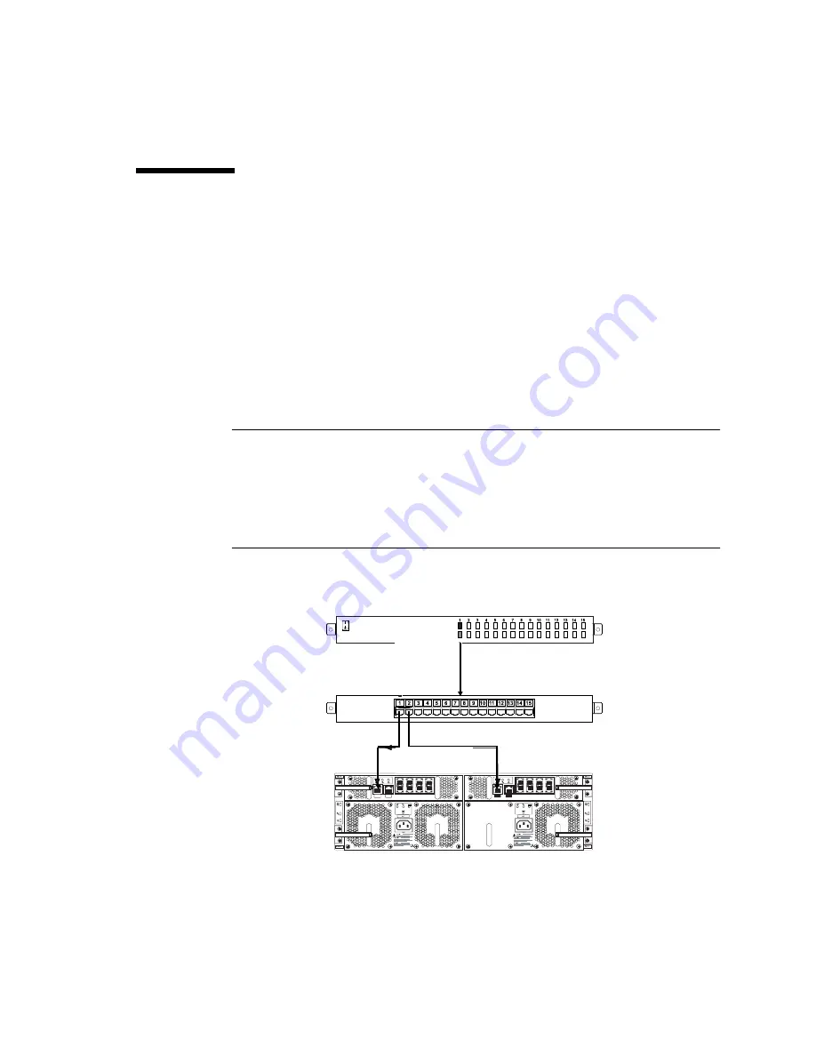
Connect a rollover cable to a patch panel and use a straight-through patch cable
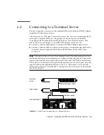
to connect the patch panel to the Sun Fire B1600 blade system chassis (see

FIGURE 6-2

).

Note –

You do not have to use a Cisco terminal server. For other terminal servers,

see the manufacturer’s documentation to confirm whether the pinouts of the serial
ports on the terminal server match the pinouts of the Sun Fire B1600 system chassis.
If they do not, write down which pins on the terminal server’s serial ports carry the
signals listed in the right-hand column in

TABLE 6-2

Then make a rollover cable

taking each of the pins on either SSC’s serial port to the correct pin on the terminal
server’s serial port.

FIGURE 6-2

Patch Panel Connections to a Terminal Server

Terminal
server

Patch panel

Sun Fire B1600

Straight-through cable

Rollover cables

Содержание Sun Fire B1600 Administration

Страница 1: ...4150 Network Circle Santa Clara CA 95054 U S A 650 960 1300 Send comments about this document to docfeedback sun com Sun Fire B1600 Blade System Chassis Hardware Installation Guide Part No 817 3430 10 August 2003 Revision A ...

Страница 2: ... DISCLAIMED EXCEPT TO THE EXTENT THAT SUCH DISCLAIMERS ARE HELD TO BE LEGALLY INVALID Copyright 2003 Sun Microsystems Inc 4150 Network Circle Santa Clara California 95054 Etats Unis Tous droits réservés Sun Microsystems Inc a les droits de propriété intellectuels relatants à la technologie incorporée dans le produit qui est décrit dans ce document En particulier et sans la limitation ces droits de...

Страница 3: ... 1 System Cooling Requirements 1 8 1 5 1 1 General Environmental Parameters 1 8 1 5 1 2 Airflow Requirements 1 11 1 5 1 3 Estimating the Heat Dissipation 1 11 1 5 2 Operating Power Limits and Ranges 1 12 1 5 3 Estimating Power Consumption 1 12 2 Rack Options and Placement 2 1 2 1 Rack Options 2 1 2 2 Service Access 2 2 2 3 Rack and Floor Loading 2 3 2 4 Rack and Cabinet Safety 2 3 3 Installing the...

Страница 4: ...ost Rack 3 12 3 3 What to Do Next 3 16 4 Removing and Installing Modules 4 1 4 1 Removing and Installing Blades or Filler Panels 4 2 4 1 1 Removing Blades or Filler Panels 4 3 4 1 2 Installing a Blade or Filler Panel 4 6 4 2 Removing and Installing a PSU 4 9 4 2 1 Removing a PSU 4 10 4 2 2 Inserting a PSU 4 12 4 3 Removing and Installing a Switch and System Controller SSC 4 15 4 3 1 Chassis Suppli...

Страница 5: ...iple System Chassis 5 12 5 8 What to Do Next 5 13 6 Connecting the RS232 Serial Port to Different Devices 6 1 6 1 Serial Port Pin Numbers 6 3 6 2 Connecting to a Terminal Server 6 4 6 3 Connecting to a VT100 Terminal or a Sun Workstation 6 5 6 4 Connecting to a Terminal That Has a 9 pin Adapter 6 6 6 5 Connecting to a Modem 6 7 6 6 Connecting the Cable to the Serial Port 6 8 6 7 Setting up a Seria...

Страница 6: ...vi Sun Fire B1600 System Chassis Hardware Installation Guide August 2003 ...

Страница 7: ...ack Bracket Spacer 3 5 FIGURE 3 5 Removing the Module Retaining Pins 3 7 FIGURE 3 6 Aligning the System Chassis to the Brackets 19 Inch Four Post Rack 3 8 FIGURE 3 7 Removing the Sacrificial Lifting Handle 19 Inch Four Post Rack 3 9 FIGURE 3 8 Tightening the Captive Retaining Screws 19 Inch Four Post Rack 3 10 FIGURE 3 9 Removing the Module Retaining Pins 3 12 FIGURE 3 10 Attaching the Two Post Fr...

Страница 8: ... 15 Removing the SSC From the System Chassis 4 18 FIGURE 4 16 Aligning the SSC Before Insertion 4 19 FIGURE 4 17 Inserting the SSC 4 20 FIGURE 4 18 Closing the SSC Ejector Lever 4 21 FIGURE 5 1 External Cable Ports One SSC and PSU Shown 5 2 FIGURE 5 2 Inserting the IEC Power Cords 5 3 FIGURE 5 3 Clipping on the Power Cord Retention Clip 5 4 FIGURE 5 4 The 10 100 1000BASE T Data Network Ports 5 7 F...

Страница 9: ...nouts 5 8 TABLE 5 2 100BASE T Network Management Port Pinouts 5 10 TABLE 6 1 Serial Port Pinouts 6 3 TABLE 6 2 Serial Port Pinouts to a Terminal Server 6 5 TABLE 6 3 Serial Port Pin Interconnections to a Sun DB 25 25 pin Adapter 6 6 TABLE 6 4 Serial Port Pin Interconnections to a DB 9 9 pin Adapter 6 7 TABLE 6 5 Default Settings for Connecting a Modem to the Serial Port 6 7 TABLE 6 6 Pin Inter con...

Страница 10: ...x Sun Fire B1600 System Chassis Hardware Installation Guide August 2003 ...

Страница 11: ...de system chassis Chapter 2 explains the various rackmount options and requirements for the system chassis Chapter 3 details how to install the system chassis into a rack Chapter 4 describes how to install a blade or filler panel in the system chassis The chapter also describes how to remove and install other components from the system chassis Chapter 5 explains how to connect the IEC power supply...

Страница 12: ...view foldout poster Sun Fire B1600 Blade System Chassis Quick Start Hardware installation Sun Fire B1600 Blade System Chassis Hardware Installation Guide this manual Software installation overview foldout poster Sun Fire B1600 Blade System Chassis Software Setup Quick Start Software setup Sun Fire B1600 Blade System Chassis Software Setup Guide B100x and B200x server blade installation and setup S...

Страница 13: ...un is interested in improving its documentation and welcomes your comments and suggestions You can email your comments to Sun at docfeedback sun com Please include the part number 817 3430 10 of your document in the subject line of your email ...

Страница 14: ...xiv Sun Fire B1600 System Chassis Hardware Installation Guide August 2003 ...

Страница 15: ...for the installation of the Sun Fire B1600 blade system chassis in the following sections Section 1 1 Checklist of Rackmounting and Setup Tasks on page 1 2 Section 1 2 Contents of the Ship Kit on page 1 3 Section 1 3 Tools and Equipment Needed on page 1 4 Section 1 4 System Chassis Dimensions on page 1 4 ...

Страница 16: ...ack or Cabinet on page 3 1 or Section 3 2 Installing the System In a Two Post Rack on page 3 11 6 Install the blades if applicable See Section 4 2 Installing a Blade or Filler Panel on page 4 5 7 Remove and re install the PSUs and SSCs if you want to check the serial numbers or familiarize yourself with the installation and removal procedures See Section 4 3 Removing and Installing a PSU on page 4...

Страница 17: ...llation Guide Sun Fire B1600 Blade System Chassis Compliance and Safety Manual Multilingual Sun Fire B1600 Blade System Chassis Software Setup Guide Sun Fire B1600 Blade System Chassis Software Quick Start Poster Sun Fire B1600 Blade System Chassis Hardware Quick Start Poster Sun Fire B100x and B200x Server Blade Installation and Setup Guide supplied only if the chassis contains B100x and or B200x...

Страница 18: ...ack or cabinet Category 5 RJ 45 cabling A maximum of 20 cables are required for a fully populated system chassis IEC power cabling Two cables are required per system chassis You will also need the following tools No 2 Phillips screwdriver The correct screwdriver for the rackmounting screws being attached to and supplied with the host rack or cabinet A cage nut insertion tool only for racks or cabi...

Страница 19: ...llation 1 5 Overall height 5 16 in 131 0mm Overall height including sacrificial lifting handles 6 22 in 158 0mm Weight fully populated 99lb 45kg TABLE 1 1 System Chassis Dimensions Continued Dimension US Measurement Metric Measurement ...

Страница 20: ...ions Top View The system chassis is designed to fit in a 800mm rack If you want to install the system chassis in a rack less than 800mm deep check the suitability of the rack before you start the installation 26 81 in 24 in 20 08 in Orange sacrificial lifting handle 681 0mm 609 6mm 17 64 in 448 0mm 510 0mm ...

Страница 21: ...Chapter 1 Preparing for the Installation 1 7 FIGURE 1 2 System Chassis Dimensions Front View 131 0mm Orange sacrificial lifting handle 5 16 in 6 22 in 158 0mm ...

Страница 22: ...ental parameters and airflow requirements for the Sun Fire B1600 blade system chassis Note The Sun Fire B1600 blade system chassis uses front to back forced air cooling 1 5 1 1 General Environmental Parameters You can operate and store the system safely in the conditions detailed in TABLE 1 2 FIGURE 1 3 and FIGURE 1 4 TABLE 1 2 Operating and Storage Specifications Specification Operating Storage A...

Страница 23: ...URE 1 3 Temperature and Altitude Operating Ranges FIGURE 1 4 Temperature and Relative Humidity Ranges Temperature C Altitude m Pressure kPa 5 35 400 106 500 95 3000 70 Moisture content Dry bulb temperature C 5 35 90 RH 10 RH 27 C wet bulb temperature ...

Страница 24: ...or humidity increases the failure rate of hardware components To minimize the chance of component failure use the server within the optimal temperature and humidity ranges Ambient Temperature An ambient temperature range of 21 C to 23 C is optimal for system reliability At 22 C it is easy to maintain safe relative humidity levels Operating in this temperature range provides a buffer in the event o...

Страница 25: ... exhaust ventilation must both have a minimum open area of 22in2 142 cm2 for each system chassis The use of perforated or solid door panels must allow adequate airflow to the system chassis when the cabinet doors are closed 1 5 1 3 Estimating the Heat Dissipation To estimate the heat generated by a Sun Fire B1600 blade system chassis convert the figure for the system s power consumption from watts...

Страница 26: ...alf of the input current during normal system operation 16A 110VAC 8A 240VAC Maximum power supply rating Currents up to the maximum power supply rating might be required for future product upgrades 12A 110VAC 6A 240VAC Maximum in rush current The in rush current decays to the normal operating current in less than 200 milliseconds Sequencing of power to multiple units is not required as the peak cu...

Страница 27: ...tions You can install the Sun Fire B1600 blade system chassis into these 19 inch and 23 inch racks 19 inch two post rack with a post depth between 3in 76 2mm and 6in 152 4mm 19 inch four post IEC297 EIA310 D rack with a distance between mounting rails from 24 6in 625 mm to 36 4in 925mm 23 inch two post rack with a post depth of 5in 127mm These are intended for use with telco seismic frames 23 inch...

Страница 28: ...sure that units or cables above a Sun Fire B1600 blade system chassis do not protrude beyond the front face of the system chassis to enable proper airflow Access to the front and back of the Sun Fire B1600 blade system chassis is required for installation and system maintenance Note If you are installing the system chassis into a cabinet that has a door you might need to swing the door back 180 de...

Страница 29: ...re B1600 blade system chassis must be anchored to the floor or to adjacent frames using the manufacturer s instructions Free standing racks or cabinets with a footprint of less than 23 6in x 23 6in 600mm x 600mm are likely to be unstable and should be treated with caution Where several system chassis are fitted in a rack or cabinet only one of them should be withdrawn for service at any one time S...

Страница 30: ...2 4 Sun Fire B1600 System Chassis Hardware Installation Guide August 2003 ...

Страница 31: ...ection 3 2 Installing the System In a Two Post Rack on page 3 11 Section 3 3 What to Do Next on page 3 16 3 1 Installing the System Chassis In a Four Post Rack or Cabinet This section contains instructions for installing a Sun Fire B1600 blade system chassis in a four post rack or cabinet The system chassis is shipped with orange sacrificial lifting handles which assist in handling the system chas...

Страница 32: ...crews One rack bracket spacer You must supply the appropriate screws to attach the brackets to any rack not supplied by Sun Microsystems 3 1 2 Using the Rack Buddy The Rack Buddy card helps you to find out which rackmount holes are appropriate for installing the system chassis 1 Hold the Rack Buddy to the rack so that the bottom of the Rack Buddy is either just above the top of a system already in...

Страница 33: ...Sliding the Front Bracket Section Into the Back Bracket Section 19 Inch Four Post Rack 2 Extend each rack bracket to the length required to fit in the rack or cabinet 3 Insert two M4 screws supplied with the rack mount kit to each bracket and finger tighten to connect the front and back bracket sections together FIGURE 3 3 Note Insert one screw through the slot furthest away from the front of the ...

Страница 34: ...each end of the bracket to the rack or cabinet using the screws appropriate to the rack or cabinet Do not fully tighten the screws Use the rack holes you noted as part of Section 3 1 2 Using the Rack Buddy on page 3 2 The mounting holes in the rack bracket are oversized to allow installation in most racks or cabinets Front of rack bracket Front edge of back bracket section ...

Страница 35: ... location pins fully in the middle hole of each rack bracket FIGURE 3 4 FIGURE 3 4 Inserting the Rack Bracket Spacer 6 Tighten the front rack bracket screws fully and remove the rack bracket spacer 7 Repeat Step 5 through Step 6 for the back of the bracket 8 Fully tighten the M4 screws in the middle of the brackets to complete the bracket installation ...

Страница 36: ... not designed to hold a system that is tipped from the horizontal position Caution When inserting the system chassis into the rack it is essential that the chassis is kept parallel to the front of the rack On final insertion into the rack apply equal force to both sides of the system chassis to ensure correct installation 1 Take the system chassis out of the packaging and place it on a flat surfac...

Страница 37: ...t 3 7 2 Remove the module retaining pins FIGURE 3 5 FIGURE 3 5 Removing the Module Retaining Pins 3 Disengage the back sacrificial lifting handle FIGURE 3 6 Slide the sacrificial lifting handle toward the back of the system chassis and then push the handle down ...

Страница 38: ...rasp the orange front sacrificial lifting handle and hold the bottom of the system chassis with your other hand Do not lift the system chassis 5 Align the system chassis to the rack brackets FIGURE 3 6 FIGURE 3 6 Aligning the System Chassis to the Brackets 19 Inch Four Post Rack 6 Slide the system chassis into the rack FIGURE 3 7 Step 3 Step 4 ...

Страница 39: ...fting handle FIGURE 3 7 Slide the sacrificial lifting handle toward the back of the system chassis and then pull down FIGURE 3 7 Removing the Sacrificial Lifting Handle 19 Inch Four Post Rack 8 Push the system chassis fully into the rack Take care to keep the system chassis straight during insertion ...

Страница 40: ...ation Guide August 2003 9 Tighten the captive retaining screws located at the front of the system chassis FIGURE 3 8 FIGURE 3 8 Tightening the Captive Retaining Screws 19 Inch Four Post Rack 10 Go to Section 3 3 What to Do Next on page 3 16 JB O S 3000 ...

Страница 41: ...andles for handling the system chassis The handles must be stored in a safe place after the system chassis is installed in a rack or cabinet Note The figures in this section are simplified to show only those rails to which the system chassis rack brackets are attached 3 2 1 Contents of the Two Post Rackmount Kit The two post rackmount kit comprises The Rack Buddy Four rackmount brackets One set of...

Страница 42: ...ssis In a Two Post Rack 1 Place the system chassis on a flat surface and remove the sacrificial lifting handles Slide the sacrificial lifting handle toward the back of the system chassis and then push the handle down 2 Remove the module retaining pins FIGURE 3 9 FIGURE 3 9 Removing the Module Retaining Pins ...

Страница 43: ...ling the System Chassis In a Rack or Cabinet 3 13 3 Attach the front brackets to the system chassis FIGURE 3 10 FIGURE 3 10 Attaching the Two Post Front Brackets to the System Chassis 19 Inch Two Post Rack JB O S 30 00 ...

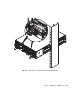
Страница 44: ...m Chassis to the Rack 19 Inch Two Post Rack Caution A fully populated system chassis weighs 99lb 45kg approximately and must be lifted by at least two people A third person is required to attach the front brackets to the rack Note The two inner rack bracket screw holes are the rackmount holes identified by the Rack Buddy See Section 3 1 2 Using the Rack Buddy on page 3 2 Inner rack bracket screw h...

Страница 45: ...m Chassis In a Rack or Cabinet 3 15 5 Attach the back brackets to the system chassis and to the two post rack FIGURE 3 12 FIGURE 3 12 Attaching the Back Brackets 19 Inch Two Post Rack 6 Go to Section 3 3 What to Do Next on page 3 16 ...

Страница 46: ...talled as A fully populated system A populated system chassis that requires the installation of blades If you have installed a system chassis that requires blade installation continue with Chapter 4 If you have installed a fully populated Sun Fire B1600 blade system chassis continue with Section 5 1 Location of Ports and Power Inlets on page 5 2 ...

Страница 47: ...r Supply Units PSUs two Switch and System Controllers SSCs and 16 filler panels This chapter provides the procedures for removing filler panels if necessary and installing blades in the system chassis It also provides instructions for removing and inserting PSUs and SSCs while the system is powered down It contains the following sections Section 4 1 Removing and Installing Blades or Filler Panels ...

Страница 48: ...s occupy two adjacent slots in the system chassis FIGURE 4 1 shows a system chassis containing single width blades and a double width blade Note Be aware that the system chassis contains three internal dividing walls Double width blades must be installed in two available slots between these internal dividing walls FIGURE 4 1 B1600 System Chassis with Single width and Double width Blades FIL LER PA...

Страница 49: ...o removal of a single width blade The same steps apply when installing a double width blade or filler panel 1 Insert your finger in the pull recess located at the bottom front of the blade lever and pull gently to disengage the locking mechanism FIGURE 4 2 FIGURE 4 2 Disengaging the Blade Locking Mechanism JB O S 3000 ...

Страница 50: ...is Hardware Installation Guide August 2003 2 Pull the lever in a forward and upward motion causing the blade lever to unlatch and eject the blade partially from the system chassis FIGURE 4 3 FIGURE 4 3 Ejecting the Blade JB O S 3000 ...

Страница 51: ...ng Modules 4 5 3 Pull the lever to remove the blade from the system chassis FIGURE 4 4 Support the bottom of the blade with your free hand while lifting the blade clear of the system chassis FIGURE 4 4 Removing the Blade JB O S 3000 ...

Страница 52: ...ternal dividing walls Double width blades must be installed in two available slots between these internal dividing walls The steps below refer to installation of a single width blade The same steps apply when installing a filler panel or double width blade 1 If required open the blade lever by inserting a finger in the pull recess located in lower portion of the blade lever and pull the lever in a...

Страница 53: ...and while lifting the blade up to the system chassis FIGURE 4 6 FIGURE 4 6 Aligning and Inserting the Blade 3 Insert the blade into the empty slot Caution Ensure that the blade engages with the system chassis guidance system Failure to align the blade correctly can result in damage to the chassis midplane or the blade connection 4 Gently push the blade into the slot until the blade latch ears on t...

Страница 54: ...dware Installation Guide August 2003 5 Close the blade lever fully by pushing it down until you feel the latch click in place This engages the blade into the chassis slot FIGURE 4 7 FIGURE 4 7 Closing the Blade Lever Mechanism JB O S 3000 ...

Страница 55: ...th the mechanism or to check the PSU Serial Number Note The procedures contained in this section assume that the system chassis is unpowered See the Sun Fire B1600 Blade System Chassis Administration Guide for instructions on removing a PSU from a powered system chassis Caution To ensure that it remains within an acceptable range of operating temperatures the Sun Fire B1600 system chassis requires...

Страница 56: ...t 2003 4 2 1 Removing a PSU 1 Squeeze the green PSU ejector lever to unlatch it and pull the lever towards you to disconnect the PSU from the system chassis FIGURE 4 8 FIGURE 4 8 PSU Ejector Lever 2 Check that the ejector lever is open fully and clear of the PSU module ...

Страница 57: ...the PSU from the system chassis by pulling on the vertical handles attached to the rear of the PSU FIGURE 4 9 Support the bottom of the PSU while removing the module from the system chassis FIGURE 4 9 Removing the PSU From the System Chassis Vertical Handles ...

Страница 58: ...n Do not install a PSU with the IEC power cord already attached Only connect the power cord when the PSU is installed 1 Correctly align the PSU with the empty PSU slot in the system chassis PSU connectors must face towards the system chassis and be located on the lower half of the PSU FIGURE 4 10 2 Check that the chassis ejector lever is opened fully and does not obstruct the opening to the PSU sl...

Страница 59: ... 13 3 Slide the PSU into the empty PSU slot Push the PSU into the slot until the ejector lever engages FIGURE 4 11 You must push the PSU firmly to raise the system flap within the system chassis FIGURE 4 11 Sliding the PSU in the System Chassis ...

Страница 60: ...allation Guide August 2003 4 Complete the installation by closing the ejector lever fully Check that the ejector lever engages onto the PSU pull handle This engages the PSU into the system chassis FIGURE 4 12 FIGURE 4 12 Closing the PSU Ejector Lever ...

Страница 61: ...connectors Note If you are removing a filler panel and replacing it with a new SSC make sure the currently installed SSC is using release 1 2 or later of the System Controller firmware Also if the module you are installing as a redundant SCC is not a new one but is taken from another chassis and does not have release 1 2 firmware installed on it you need to upgrade it on the old chassis before ins...

Страница 62: ...4 16 Sun Fire B1600 System Chassis Hardware Installation Guide August 2003 FIGURE 4 13 Rear View of the Chassis Showing a Filler Module in Slot SSC1 ...

Страница 63: ...e SSC 1 Squeeze the green SSC ejector lever to unlatch it and then pull the lever towards you to disconnect the SSC from the system chassis FIGURE 4 14 FIGURE 4 14 SSC Ejector Lever 2 Check that the ejector lever is open fully and clear of the SSC module FIGURE 4 14 ...

Страница 64: ...August 2003 3 Remove the SSC from the system chassis by pulling on the vertical handles attached to the back of the SSC FIGURE 4 15 Support the bottom of the SSC while removing the module from the system chassis FIGURE 4 15 Removing the SSC From the System Chassis ...

Страница 65: ...he SSC with the system chassis SSC connectors must face towards the system chassis and be located on the lower half of the SSC 2 Ensure that the chassis ejector lever is opened fully and does not obstruct the chassis opening FIGURE 4 16 FIGURE 4 16 Aligning the SSC Before Insertion ...

Страница 66: ...Fire B1600 System Chassis Hardware Installation Guide August 2003 3 Slide the SSC into the empty chassis slot Push the SSC into the slot until the ejector lever engages FIGURE 4 17 FIGURE 4 17 Inserting the SSC ...

Страница 67: ...nstalling Modules 4 21 4 Complete insertion by closing the ejector lever Check that the latch engages onto the SSC pull handle This engages the SSC into the system chassis FIGURE 4 18 FIGURE 4 18 Closing the SSC Ejector Lever ...

Страница 68: ...600 System Chassis Hardware Installation Guide August 2003 4 4 What to Do Next Now you have a fully populated Sun Fire B1600 blade system chassis continue with Section 5 1 Location of Ports and Power Inlets on page 5 2 ...

Страница 69: ...0BASE T and 10 100BASE TX Connections on page 5 5 Section 5 4 Attaching the Connector Cables on page 5 6 Section 5 5 Connecting to the 10 100 1000BASE T Data Network Ports on page 5 7 Section 5 6 Connecting to the 10 100BASE T Network Management Ports on page 5 10 Section 5 7 Managing Cables for Multiple System Chassis on page 5 12 Section 5 8 What to Do Next on page 5 13 See Chapter 6 for details...

Страница 70: ...1 External Cable Ports One SSC and PSU Shown Caution Do not connect a telephone jack connector to a RJ 45 port This can damage the switch Instead use only twisted pair cables with RJ 45 connectors that conform with FCC standards and make sure you follow local national wiring or electrical regulations 10 100 1000BASE T data IEC power inlet network ports 10 100BASE T network management port RS232 se...

Страница 71: ...necting each power cord to a separate circuit breaker will ensure that failure of one circuit does not compromise the system 1 Connect the power cord to the IEC power inlet FIGURE 5 2 Note The Sun B1600 blade system chassis powers on when the power cords are connected Connection of the power cord provides a reliable earth to ground FIGURE 5 2 Inserting the IEC Power Cords ...

Страница 72: ...t might not be fully inserted into the system enclosure See Section 4 3 Removing and Installing a PSU on page 4 8 for details of how to install the PSU correctly Caution Do not attempt to install a PSU with the power cord attached 3 Use the power cord retention clip to hold the power cord in position FIGURE 5 3 FIGURE 5 3 Clipping on the Power Cord Retention Clip 4 Repeat Step 1 through to Step 3 ...

Страница 73: ...fication includes test parameters that are only recommendations for Category 5 Therefore the first step in preparing existing Category 5 UTP cable for running 1000BASE T is a simple test of the cable installation to confirm that it complies with the IEEE 802 3ab standards 5 3 1 1 Cable Testing for Existing Category 5 Cable Installed Category 5 UTP cables must pass tests for Attenuation Near End Cr...

Страница 74: ...sted pair cables must not exceed 100 meters 328 feet in length Note When connected to a shared collision domain such as a hub with multiple workstations switch ports must be set to half duplex mode and back pressure flow control must be disabled to avoid propagating jamming packets throughout the segment 5 4 Attaching the Connector Cables You must connect the power cords to the PSUs before you att...

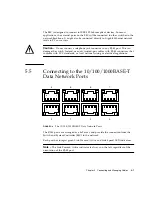
Страница 75: ...ted pair cables with RJ 45 connectors that conform with FCC standards or local national wiring or electrical regulations 5 5 Connecting to the 10 100 1000BASE T Data Network Ports FIGURE 5 4 The 10 100 1000BASE T Data Network Ports The RJ 45 ports are arranged as a 4x2 array and provide the connection from the Switch and System Controller SSC to the network Each port has integral green Link Presen...

Страница 76: ...ng it indicates that a link is established and packets are being transferred FIGURE 5 5 shows how to connect the data network cables to the system chassis If you intend to configure your system chassis with redundant data connections see Chapter 3 of the Sun Fire B1600 Blade System Chassis Software Setup Guide for details of how to duplicate connections from the SSC to your network TABLE 5 1 10 10...

Страница 77: ...Chapter 5 Connecting and Managing Cables 5 9 FIGURE 5 5 Attaching the Data Network Cables to the Network Ports ...

Страница 78: ...t Active and Link Speed indicators FIGURE 5 6 10 100BASE T Network Management Ports When LED A is illuminated constantly it indicates that a link is established but no packets are being transferred When LED A is flashing it indicates that a link is established and packets are being transferred Note 4T_D3P and 4T_D4P pins provide a common mode termination for unused lines FIGURE 5 7 shows how to co...

Страница 79: ...Chapter 5 Connecting and Managing Cables 5 11 FIGURE 5 7 Attaching the Network Management Cables ...

Страница 80: ... to avoid blocking airflow through the system chassis Check that Cables are of an adequate length There is adequate clearance at the back of the system chassis The cabling from multiple system chassis does not block the back vents of any system chassis that is installed beneath them Cable management rings are attached to the module ejector handles on each PSU and SSC Use each ring to gather the ca...

Страница 81: ...system chassis clear might cause the system chassis to overheat and lead to system shutdown 5 8 What to Do Next See Chapter 6 for details of how to connect the Serial Port to different types of device such as a Terminal server VT100 terminal or Sun Workstation Terminal that has a 9 pin adapter Modem ...

Страница 82: ...5 14 Sun Fire B1600 System Chassis Hardware Installation Guide August 2003 ...

Страница 83: ...rmally and neither is damaged by default SSC0 contains the active System Controller and SSC1 contains the standby System Controller This means that to set up the chassis for the first time using a serial connection you need a serial connection to at least SSC0 However for day to day operation of the blade system chassis we recommend you set up serial connections to both SSCs This ensures that if t...

Страница 84: ... Fire B1600 blade system chassis from the back pin 1 of the RJ 45 serial port is on the left and pin 8 is on the right FIGURE 6 1 Serial Port Pin Numbers TABLE 6 1 Serial Port Pinouts Pin number on System Chassis Signal Pin 1 RTS Pin 2 DTR Pin 3 TXD Pin 4 Signal Ground Pin 5 Signal Ground Pin 6 RXD Pin 7 DSR Pin 8 CTS 8 1 ...

Страница 85: ...a rollover cable to a patch panel and use a straight through patch cable to connect the patch panel to the Sun Fire B1600 blade system chassis see FIGURE 6 2 Note You do not have to use a Cisco terminal server For other terminal servers see the manufacturer s documentation to confirm whether the pinouts of the serial ports on the terminal server match the pinouts of the Sun Fire B1600 system chass...

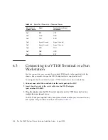
Страница 86: ...n the SSC 2 Insert the other end of the serial cable into the DB 25 adapter part number 530 2889 3 Plug the adapter into the DB 25 serial connector on the VT100 terminal or Sun workstation you intend to use The DB 25 adapter supplied with your system chassis enables you to connect to any Sun system The pin interconnections are listed in TABLE 6 3 TABLE 6 2 Serial Port Pinouts to a Terminal Server ...

Страница 87: ...e rollover cable see Section 6 2 Connecting to a Terminal Server on page 6 3 1 Connect one end of the serial cable to the serial port on the SSC 2 Insert the other end of the serial cable into the DB 9 adapter TABLE 6 3 Serial Port Pin Interconnections to a Sun DB 25 25 pin Adapter Serial Port RJ 45 Connector Pin 25 pin Connector Pin 1 RTS Pin 5 CTS Pin 2 DTR Pin 6 DSR Pin 3 TXD Pin 3 RXD Pin 4 Si...

Страница 88: ...cable into the DB 25 adapter that was supplied with the system chassis part number 530 2889 3 Plug the adapter into the DB 25 serial connector on the modem The settings you need to use for a modem connection are listed in TABLE 6 5 TABLE 6 4 Serial Port Pin Interconnections to a DB 9 9 pin Adapter Serial Port RJ 45 Connector Pin 9 pin Connector Pin 1 RTS Pin 8 CTS Pin 2 DTR Pin 6 DSR Pin 3 TXD Pin...

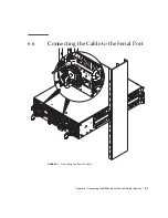
Страница 89: ...Chapter 6 Connecting the RS232 Serial Port to Different Devices 6 7 6 6 Connecting the Cable to the Serial Port FIGURE 6 3 Attaching the Serial Cables ...

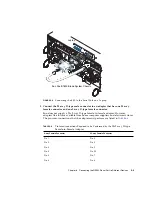
Страница 90: ...e installed the blade system chassis into a rack or cabinet refer to Chapter 3 before following the instructions in this chapter 6 7 1 Connecting to a Laptop Note Do not attempt to use the laptop s 25 pin parallel port instead of its serial port The serial port is a male 9 pin D type connector 1 Connect the RJ 45 to RJ 45 patch cable supplied with the chassis to the SSC s serial port 2 Connect the...

Страница 91: ...a 25x9 way D type female to female adapter However adapters like this are available from home computer suppliers and electronics stores The pin inter connections that the adapter must perform are listed in TABLE 6 6 TABLE 6 6 Pin Inter connections Required to be Performed by the 25x9 way D type Female to Female Adapter 9 way Female Connector 25 way Female Connector Pin 1 Pin 8 Pin 2 Pin 3 Pin 3 Pi...

Страница 92: ...erTerminal window double click the Hypertrm exe icon 3 In the Connection Description window specify a name for the HyperTerminal connection you are creating on the laptop Then select an icon for it and click OK 4 In the Connect to window click the arrow for the Connect using option and select the port you are using for your connection to the server Unless you have a particular reason for using a d...

Страница 93: ...he Properties window click the Settings tab On the Settings tab click the arrow for the Emulation option and select VT100 For the Telnet terminal option specify VT100 Click OK 6 8 What to Do Next For information on how to configure the system controllers Switches and blades within the system chassis see the Sun Fire B1600 Blade System Chassis Software Setup Guide ...

Страница 94: ...6 12 Sun Fire B1600 System Chassis Hardware Installation Guide August 2003 ...

Страница 95: ...able 5 5 external cable ports 5 2 maximum length of twisted pair cables 5 6 captive retaining screws tightening 3 10 Cisco AS2511 RJ terminal server 6 6 connecting the cables connecting to the serial port 6 8 to a modem 6 7 to a Sun workstation 6 5 to a terminal server 6 4 to a terminal that has a 9 pin adapter 6 6 to a VT100 terminal or Sun workstation 6 5 cooling requirements 1 8 crossover cable...

Страница 96: ... adapter 6 6 pinouts to a terminal server 6 5 power estimating power consumption 1 12 power consumption of individual components 1 12 power limits and ranges 1 12 Power Supply Unit see PSU PSU closing the ejector lever 4 12 ejector lever 4 10 inserting 4 12 number of PSUs required 4 9 removing 4 10 R rack contents of the four post rakmount kit 3 2 rack options 2 1 vertical mounting hole pattern 2 ...

Страница 97: ...4 19 removing the SSC 4 17 Sun Fire B1600 blade system chassis estimating heat dissipation 1 11 Sun workstation connecting to the serial port 6 5 Switch and System Controller see SSC T temperature operating ambient temperature 2 3 terminal server 6 4 twisted pair cables maximum length 5 6 V VT100 terminal connecting to the serial port 6 5 W weight considerations 2 3 weight distribution hazard 2 3 ...

Страница 98: ...Index 4 Sun Fire B1600 System Chassis Hardware Installation Guide August 2003 ...

Отзывы: