


14
Operation & Maintenance Manual
Cyclo® BBB5
Cyclo® BBB5
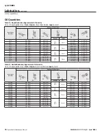
Removal from Driven Shaft
Removal of Cyclo® BBB5 with Keyed Hollow Bore, Removal of Cyclo® BBB5 with Shrink Disc
Table 6: Removal Jig Dimensions
Internal Snap Ring a
Spacer: Threaded f
Bolt
g
Thrust Disc h
A3
A8
Removal of Cyclo® BBB5 with Shrink Disc
Before starting unit removal process, ensure that electrical power to unit has
been safely locked out and that electrical connections to the unit have been
disconnected .
1
Externally support the Cyclo® BBB5 unit such that all unit weight is removed from the
driven shaft .
The weight of the Cyclo® BBB5 must be externally supported throughout the
entire removal process .
Do not raise the unit too high . Shaft binding may occur .
2
If required, remove the safety cover and apply liquid penetrant to the shrink disc
bolts and shaft/bore allowing adequate time for proper penetration .
Loosen the locking bolts on the shrink disc . Complete bolt removal should not be
required .
Tapping the shrink disc flanges with a wooden or hard rubber mallet may be
required if any fretting corrosion has occurred .
3
Remove the gearbox from the shaft .
If shaft removal is difficult, a jig such as the one shown in the Keyed Hollow Bore
section may be used to ease the removal process:
Sumitomo does not supply the
removal jig . This information is supplied for reference only .
Size
a
f
g
h
CC (ISO/JIS)
A3
BOLT
A8
5Z
45
19
M24×250
5
5A
55
19
M24×250
5
5B
65
19
M24×300
5
5C
75
19
M24×300
5
Loosen Locking Bolts


