16E / 16E-H / 16E-P Spray Gun
66
MAN 96150 EN 01
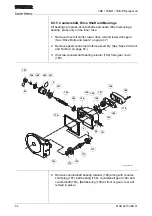
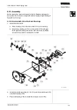
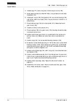
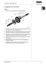
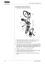
3. Install torsion spring (81) in flange of gas head subassembly (85).
The spring’s longer free end fits in the slot of the flange and the
shorter free end points downward.
4. Install spring bushing (80) on torsion spring (81).
5. Slide torsion ring (79) over spring bushing (80) and torsion spring
(81). Torsion ring is cut to fit precisely over spring and bushing.
Slide torsion ring all the way to the flange (clears pawl).
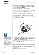
6. Slide end cap (77) onto valve core (82) so that pin in end cap
mates with slot in torsion ring (79).
7. Make sure gas valve is in closed position (handle forward).
8. Grasp torsion ring (79) firmly and apply tension to spring by rotat-
ing counterclockwise 1/2 turn.
9. Insert end cap pin (78) into end cap (77). Make sure the end cap
pin is oriented so that the hole in end cap pin will line up with the
hole in end cap. Once the end cap pin is all the way through the
valve core shaft, release the torsion ring.
10. Using a small screwdriver, align holes in end cap pin (78) and end
cap (77) and install screw (76).
11. Install torsion ring cover (75) and secure with three screws (74).
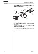
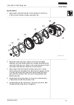
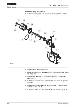
12. With spray gun inverted, install o-ring (96) in (larger) air valve port
of gas head subassembly (85).
13. Install two o-rings (97) in fuel and oxygen ports of gas head subas-
sembly (85).
14. Install o-ring (94) on air plunger (95).
16e_tortion
180º CCW
CAUTION
The valve plungers are
radiused and keyed for
orientation to mate with
the valve core. The o-
rings between the
plungers and valve core
(96, 97) are special. Do
not substitute o-rings
with non-Sulzer Metco
parts. Do not clean o-
rings with solvent. Use
only Krytox® on all o-
rings.

